Nintendo GameCube
Console de Nintendo (2001), à mini-disques optiques, CPU PowerPC « Gekko » et GPU ATI « Flipper ». Points préservation : le port numérique des DOL-001 (base des mods HDMI modernes), l'ODE GC Loader, et une RGB native propre.
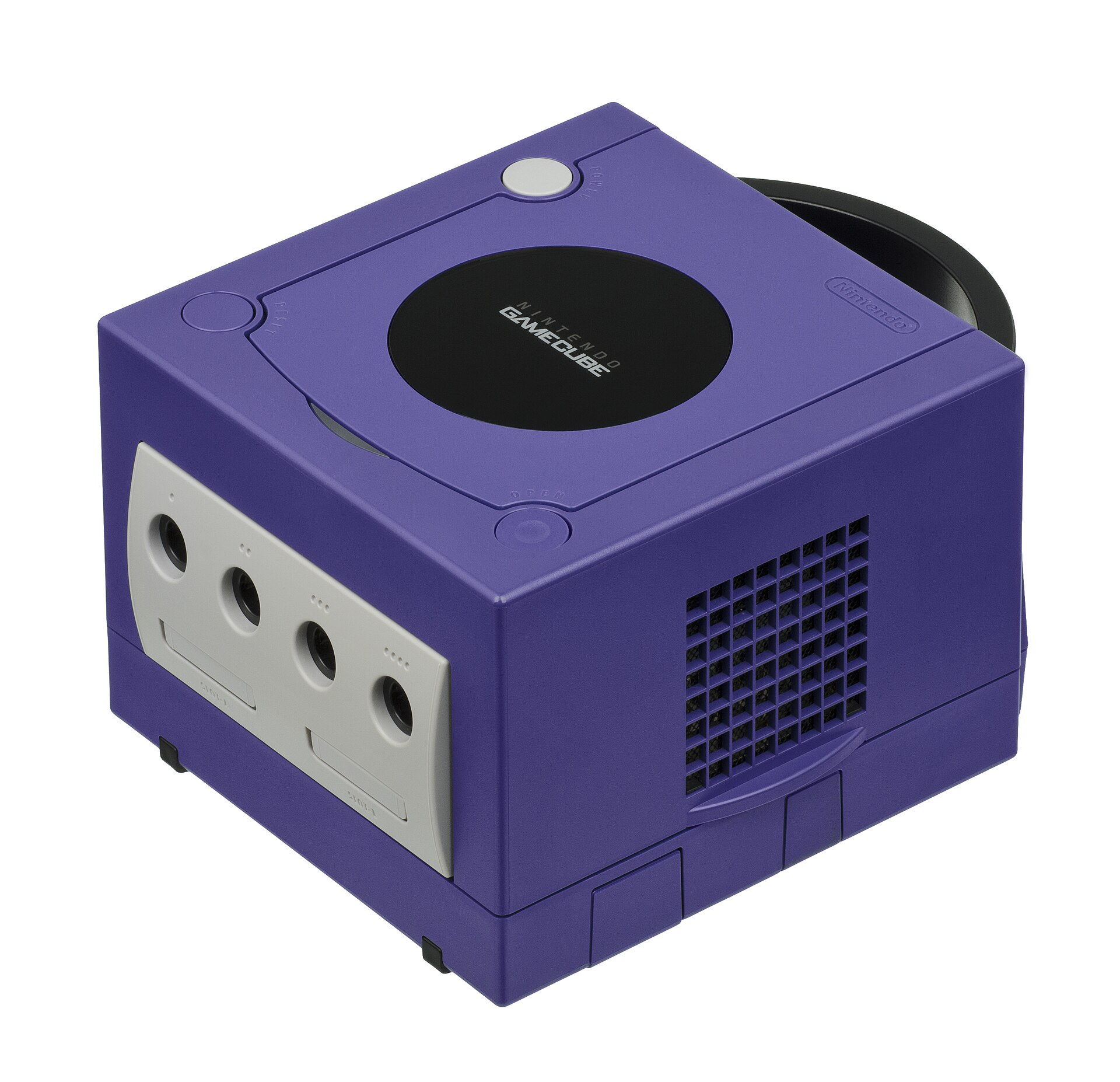
Identification
| Champ | Valeur |
|---|---|
| Fabricant | Nintendo |
| Sortie | 2001 (JP/US), 2002 (EU) |
| Génération | 6e |
| Modèles | DOL-001 (port numérique) · DOL-101 (sans port numérique) |
| Sortie vidéo | Composite, S-Video, RGB natif (Péritel), Component (DAC), numérique (DOL-001) |
| Région / lockout | JP / US / EU |
| Média | mini-disque 8 cm (~1,5 Go) |
Architecture (détail)
| Bloc | Puce | Fréquence | Notes |
|---|---|---|---|
| CPU | IBM PowerPC Gekko (base 750CXe) | 485 MHz | SIMD « paired singles » |
| GPU | ATI/ArtX Flipper | 162 MHz | intègre 3 Mo de 1T-SRAM (framebuffer/textures) |
| RAM | 24 Mo 1T-SRAM (principale, 324 MHz) + 16 Mo DRAM (aux/audio) | Faible latence | |
| Média | mini-DVD 8 cm (~1,5 Go) | lecteur Matsushita |
Le port numérique (Digital AV, DOL-001) expose la vidéo numérique brute → base des mods HDMI (GCVideo / Carby / GCDual). Le DOL-101 l'a supprimé. Côté audio, un DSP dédié (Macronix) gère 64 voix ADPCM et le Dolby Pro Logic II (surround sur certains jeux).
Connectique & accessoires
- Liaison GBA (câble link) : une Game Boy Advance sert de manette + 2ᵉ écran (Four Swords Adventures, Metroid Prime, The Wind Waker, Animal Crossing + e-Reader) — une signature GameCube.
- Game Boy Player : add-on sous la console pour jouer aux jeux GB/GBC/GBA sur TV (nécessite un disque de démarrage ; le homebrew GBI/Swiss le remplace avantageusement).
- Broadband / Modem Adapter (Serial Port 1) : jeu en ligne (Phantasy Star Online) et LAN (Mario Kart: Double Dash!!, 1080°, Kirby Air Ride).
- Manettes : stick à grille octogonale (culte pour Smash), WaveBird (sans fil RF, sans rumble), DK Bongos.
- Panasonic Q (Japon) : GameCube + lecteur DVD dans un boîtier inox Panasonic.
Pannes fréquentes
| Symptôme | Cause probable | Piste |
|---|---|---|
| Ne lit plus les disques | Lecteur optique usé | ODE GC Loader (SD), ou remplacer le lecteur |
| Pas d'image numérique | Modèle DOL-101 (sans port numérique) | Utiliser un DOL-001 pour les mods HDMI |
| Cartouche mémoire non lue | Contacts | Nettoyage |
Procédures de démontage pas-à-pas ✅
9 procédures traduites depuis les guides iFixit, avec leur difficulté et leur durée estimée. Le titre d'origine est rappelé sous chaque procédure, pour retrouver le guide et ses photos.
| Procédure | Difficulté | Durée |
|---|---|---|
| Ouverture du boîtier | 🟢 très facile | 1-2 minutes |
| Remplacement de la carte mère | 🟡 moyen | 20 à 30 minutes |
| Remplacement du lecteur optique | 🟡 moyen | 30 à 45 minutes |
| Augmenter la puissance du laser | 🟢 facile | — |
| Nettoyage du ventilateur | 🟡 moyen | 7 minutes |
| Dépose des panneaux avant et arrière | 🟢 facile | 5 minutes |
| Démontage du bloc lecteur optique | 🟡 moyen | 30 minutes |
| Démontage du bloc lecteur optique | — | — |
| Démontage intégral (teardown) | 🟡 moyen | — |
Ouverture du boîtier
Retirer la coque extérieure donne accès aux organes internes de la GameCube.
- Retourne la console et repère les quatre vis situées dans les angles.
- Retire les quatre vis d'angle sous la console avec un tournevis Gamebit 4,5 mm.
Titre d'origine : « Disassembling Nintendo GameCube Exterior Case ».
Remplacement de la carte mère
Comment déposer la carte mère de la GameCube et la remplacer.
- Une fois le bloc lecteur optique déposé, la console se présente ainsi.
- Retire les 6 vis du dissipateur avec un tournevis cruciforme n° 1.
- Soulève doucement la carte mère hors de son support.
Titre d'origine : « Installing Nintendo GameCube Motherboard ».
Remplacement du lecteur optique
Comment remplacer un lecteur optique défaillant.
- Fais glisser avec précaution le bloc optique hors de son ensemble.
- Introduis le lecteur neuf dans la console de la même façon que l'ancien en est sorti.
Titre d'origine : « Installing Nintendo GameCube Optical Drive ».
Augmenter la puissance du laser
Corrige les disques mal lus. ⚠️ Un laser poussé s'use plus vite : à ne faire qu'après avoir nettoyé la lentille, et par petits pas.
- Oriente le bloc de façon à avoir la carte verte face à toi.
- Retourne la carte pour l'orienter comme sur la seconde photo.
- Avec un tournevis cruciforme n° 1, tourne le petit potentiomètre d'un quart de tour dans le sens horaire.
Titre d'origine : « Turning up the Laser Power ».
Nettoyage du ventilateur
Comment déposer et nettoyer le ventilateur — de quoi éviter la surchauffe de la console.
- Dévisse les deux vis qui tiennent le bloc ventilateur, avec un tournevis cruciforme n° 2.
- Débranche avec précaution le connecteur beige. Ne tire pas sur les fils mais sur le connecteur lui-même.
Titre d'origine : « Repairing Nintendo GameCube Cleaning the Cooling Fan ».
Dépose des panneaux avant et arrière
Retirer ces panneaux donne accès à d'autres organes de la console.
- Appuie sur les clips et retire le panneau arrière.
- Déclipse avec précaution le bloc des ports manette, à l'avant.
- Une nappe reste attachée à la console : ne la débranche pas.
Titre d'origine : « Repairing Nintendo GameCube Front and Back Panel ».
Démontage du bloc lecteur optique
Comment démonter le bloc lecteur optique pour accéder au lecteur et au laser.
- À ce stade, le bloc lecteur doit être séparé de la console et se présenter ainsi.
- Retourne le bloc et retire les 8 vis indiquées.
- Retire la plaque métallique, sans déranger la nappe brune.
- Retire le fil bleu.
- Avec un tournevis cruciforme n° 1, retire 4 vis.
- La quatrième vis se trouve derrière le tournevis, sur la troisième photo.
- Bascule la carte comme indiqué, en prenant garde à ne sectionner ni le fil rouge ni la nappe blanche.
- Repère le fil rouge.
- Repère la nappe.
- Avec un tournevis plat, libère avec précaution les quatre clips plastique qui tiennent le bloc.
- Le dernier clip est difficile à trouver : passe le tournevis derrière le plastique comme sur la troisième image.
- Soulève la plaque métallique du bloc, toujours sans sectionner les deux fils qui relient encore les deux moitiés.
- Retourne et pivote le bloc pour l'orienter comme sur la troisième photo.
- Libère deux clips supplémentaires à l'arrière du bloc.
- Le dernier clip n'a pas besoin d'être libéré : la moitié supérieure coulisse hors de la moitié inférieure.
- Termine la dépose de la moitié supérieure avec précaution : c'est sur elle que sont fixés les deux fils à ne pas retirer — sauf à vouloir ressortir le fer à souder.
Titre d'origine : « Repairing Nintendo GameCube Optical Drive Assembly ».
Démontage du bloc lecteur optique
Comment démonter le bloc lecteur optique pour accéder au lecteur et au laser.
- À ce stade, le bloc lecteur doit être séparé de la console et se présenter ainsi.
- Retourne le bloc et retire les 8 vis indiquées.
- Retire la plaque métallique, sans déranger la nappe brune.
- Retire le fil bleu.
- Avec un tournevis cruciforme n° 1, retire 4 vis.
- La quatrième vis se trouve derrière le tournevis, sur la troisième photo.
- Bascule la carte comme indiqué, en prenant garde à ne sectionner ni le fil rouge ni la nappe blanche.
- Repère le fil rouge.
- Repère la nappe.
- Avec un tournevis plat, libère avec précaution les quatre clips plastique qui tiennent le bloc.
- Le dernier clip est difficile à trouver : passe le tournevis derrière le plastique comme sur la troisième image.
- Soulève la plaque métallique du bloc, toujours sans sectionner les deux fils qui relient encore les deux moitiés.
- Retourne et pivote le bloc pour l'orienter comme sur la troisième photo.
- Libère deux clips supplémentaires à l'arrière du bloc.
- Le dernier clip n'a pas besoin d'être libéré : la moitié supérieure coulisse hors de la moitié inférieure.
- Termine la dépose de la moitié supérieure avec précaution : c'est sur elle que sont fixés les deux fils à ne pas retirer — sauf à vouloir ressortir le fer à souder.
Titre d'origine : « Repairing Nintendo GameCube Optical Drive Assembly ».
Démontage intégral (teardown)
Sortie en 2001, la GameCube était la deuxième console la plus puissante de son temps, sans aucune fonction multimédia annexe.
- Retourne la console et retire les vis au fond des quatre trous d'angle, avec un embout Gamebit 4,5 mm. Ne retire pas encore la coque.
- Remets la console à l'endroit, puis soulève la coque supérieure : elle vient sans effort.
- Déclipse le cache des ports manette et le cache d'entrées/sorties arrière, en libérant les deux ergots de chaque côté. Ne retire pas encore le panneau des manettes.
- Retire ensuite les dissipateurs des lecteurs de carte mémoire — c'est une étape obligatoire.
- Commence maintenant à retirer les vis cruciformes n° 2 ordinaires.
- Commence par le bloc ventilateur.
- Puis dévisse les 12 vis visibles sur le pourtour de la console.
- Tu peux à présent soulever le bloc lecteur. Il faut parfois le décoller un peu au tournevis ou au spudger renforcé.
- La carte mère est maintenant visible.
- Retire le dissipateur en dévissant ses six vis.
- Sers-toi d'un objet plat et solide glissé sous l'aluminium pour faire doucement levier.
- Prudence avec l'outil : si le dissipateur résiste, chauffe les pads thermiques au sèche-cheveux ou au décapeur et dévisse-le à la main en le faisant pivoter.
- S'il reste des pads thermiques sur les processeurs ou les puces mémoire, retire-les au spudger plastique.
- Débranche le connecteur du panneau des ports manette en le soulevant et en le remuant doucement : il vient facilement.
- Mémoire : 24 Mo de MoSys 1T-SRAM.
- GPU : ATI « Flipper », 162 MHz, avec 3 Mo de 1T-SRAM intégrés au die.
- CPU : IBM « Gekko », 486 MHz (cœur dérivé du PowerPC 750CXe).
- Connecteurs (seconde photo) :
- « Hi Speed Port ».
- « Serial Port 1 ».
- « Serial Port 2 ».
- En soulevant la carte mère, on découvre une plaque métallique, sans doute un blindage. Retire ses deux vis pour accéder à l'alimentation interne.
Titre d'origine : « Nintendo GameCube Teardown ».
Source, licence et portée
Guides iFixit, sous Creative Commons BY-NC-SA — attribution, usage non commercial, partage à l'identique. Le texte est traduit de l'anglais ; le titre d'origine est rappelé sous chaque procédure et les photos d'étapes restent sur iFixit. ⚠️ Ces guides visent le modèle nommé dans le titre : sur une autre révision, la visserie et l'ordre de dépose peuvent différer.
Procédure — console morte, dans l'ordre ✅
Ce que cette procédure ajoute
Un ordre pensé pour une console, pas pour une carte arcade : ce qui tue ces machines n'est presque jamais le CPU. C'est, dans l'ordre réel, l'alimentation, les condensateurs, le lecteur ou le slot de cartouche, et la logique seulement ensuite. → Diagnostic PCB
1. L'alimentation. Deux cas selon la machine. Bloc externe : ⚠️ lire le marquage sur la machine, à côté de la prise, et vérifier l'adaptateur en face — tension et polarité. Une machine à centre négatif alimentée en centre positif y laisse son fusible, parfois son régulateur ; ne pas se fier à l'étiquette d'un bloc tiers ni à un embout universel. Alimentation interne (la machine se branche directement au secteur) : le secteur est dans le boîtier. Débrancher, attendre, et vérifier que les gros condensateurs sont déchargés avant de toucher la carte. Dans les deux cas, mesurer en charge : un bloc fatigué tient sa tension jusqu'à ce qu'on lui demande du courant.
2. Le fusible. Beaucoup de ces machines en ont un juste derrière la prise — c'est la pièce faite pour mourir. Le tester en continuité, hors circuit. Un fusible qui resaute est un court-circuit, pas un problème de fusible.
3. Les condensateurs. Sur la plupart des machines de cet âge, c'est le suspect par défaut et non le dernier recours — les électrolytiques CMS qui fuient rongent les pistes dessous avant de donner le moindre autre signe. ⚠️ Toutes n'en sont pas là : certaines en portent très peu et ne se recappent pas par principe. Lire ce que cette page en dit avant de sortir le fer. → Recap
4. Le lecteur. Sur cette machine, c'est le poste de panne dominant. Dans l'ordre : le plateau/tiroir bouge-t-il, le disque tourne-t-il, la lentille est-elle propre (coton-tige, alcool isopropylique, sans appuyer), les rails coulissent-ils librement. Un laser qui ne lit plus se remplace ; le potentiomètre de gain ne se retouche pas à l'aveugle, c'est le geste qui achève un laser encore bon.
5. La sortie vidéo. Isoler la machine de l'affichage : un autre câble, une autre télé, une autre entrée. Une part non négligeable des « consoles mortes » est un câble mort, ou un afficheur qui n'accroche pas ce que la machine sort — voir la section vidéo de cette page pour savoir quoi.
6. Toujours rien. Maintenant, et seulement maintenant, la logique : rails sur la carte, reset, horloge, bus. → Diagnostic PCB
Liste des condensateurs (carte logique NTSC, par repère CXX) ✅
Source : Console5 TechWiki. Carte logique NTSC (le PAL diffère légèrement) :
| Repère | µF | V |
|---|---|---|
| C1, C3 | 33 | 25 |
| C2 | 220 | 25 |
| C115, C116, C118 | 10 | 16 |
| C155, C156 | 220 | 6,3 |
Les cartes DC/DC (convertisseurs) et les alims externes ont de nombreuses variantes (Mitsumi, Sharp, TDK, Zebra…) avec des listes propres — voir Console5 selon ta référence.
Mods populaires — quoi acheter, où, procédures
Point crucial à l'achat : le port numérique
La sortie HDMI se branche sur le port AV numérique présent uniquement sur les DOL-001. Les DOL-101 (révision tardive) n'ont PAS ce port → pour l'HDMI il faut le remettre (mod « Digital Port Upgrade ») ou passer par le component/RGB. Procédures d'après ConsoleMods (CC-BY-SA).
Vidéo — HDMI (image parfaite, DOL-001)
- Tout repose sur le cœur GCVideo : adaptateurs GCHDMI, Carby (HDMI), GCDual (PixelFX, HDMI + Component), EON GCHD MKII, GCPlug, Pluto IIx, HDPrism, Retro GEM. Plug-and-play 🟢 (dans le port numérique) pour la plupart. → fiche GameCube numérique.
- RGB analogique : natif sur les GameCube PAL/EU (DOL-001 européennes) → câble RGB-péritel, aucun mod. Les GC NTSC ne sortent pas de RGB analogique (composite/S-Video seulement) → passer par le port numérique (GCVideo) ou le component officiel. (Rien à souder : c'est une question de câble + région, pas de point de soudure.)
Jeux sur SD — ODE (remplacer le lecteur GOD/DVD)
- GC Loader PNP ou CubeODE : remplacent le lecteur optique par une carte SD. → fiche GC Loader.
- SD2SP2 / SD Gecko : carte SD via un port série (Serial Port 2 sous la trappe, ou Memory Card) — plus lent, sert surtout à lancer Swiss/homebrew et à charger des jeux depuis SD.
Lancer du homebrew / region-free — softmod
- PicoBoot : on flashe l'IPL (le boot) via un Raspberry Pi Pico (~5 fils soudés sur des points de test de la carte) → la console boote directement sur Swiss depuis une SD. Modchip open-source, ~5 €.
- Swiss : le « couteau suisse » homebrew — region-free, force le 480p, lance les jeux depuis
SD/ODE, patchs. → Softmods. Outil open-source archivé chez nous (
files/tools/gamecube/swiss-gc).
Recap / audio
- Replacing Capacitors (kit condensateurs) sur les modèles concernés. Digital Audio (SPDIF) Mod pour l'audio optique.
Préservation & softmod
- Le mini-DVD 8 cm utilise un format propriétaire (piste BCA/« barcode », secteurs non standard) illisible par un lecteur PC → d'où l'intérêt des ODE et du dumping via Swiss (câble broadband / SD).
- Softmod sans matériel via des exploits de sauvegarde (SD Media Launcher,
exploits de jeux) qui lancent Swiss — la boîte à outils GameCube (boot DVD-R,
ODE, région, forçage progressif/480p, dumping). → outil open-source archivé chez
nous (
swiss-gc). - Émulation : très mûre (Dolphin, HD + widescreen).
Photos / assets
(À ajouter : carte, port numérique DOL-001, lecteur, sorties AV.)
Réparation avancée
Lecteur optique (laser / potard de gain) ou remplacement ODE (GC Loader) ; recap. Méthodes : ODE (GC Loader) · Recap · Diagnostic PCB.
Sources & attribution
- Wikipédia — GameCube — CC-BY-SA — https://fr.wikipedia.org/wiki/GameCube
- Console5 TechWiki — GameCube (BOM recap carte logique/DC-DC/alim par repère) — https://wiki.console5.com/wiki/GameCube
- ConsoleMods — GameCube (HDMI, GC Loader, RGB) — à référencer — https://consolemods.org/wiki/GameCube
Image :
-
gamecube-console.jpg— Evan-Amos, domaine public — https://commons.wikimedia.org/wiki/File:Nintendo-GameCube-Console-FL.jpg

Relecture & corrections
À quoi sert cet espace
Une valeur fausse, une procédure dépassée, une référence de puce qui ne colle pas à ta carte ? Signale-le ici, avec ce que tu as constaté (modèle, révision de carte, numéro de série, mesure). Chaque signalement est recoupé avec une source avant toute modification — une correction invérifiable est publiée en tant que « signalé par …, non recoupé » plutôt qu'appliquée en silence.
La lecture est ouverte à tous ; écrire demande une connexion Discord. Les signalements des relecteurs déclarés du wiki sont traités en priorité ; les autres sont lus aussi, mais passent par un humain avant toute modification.