Nintendo GameCube
Nintendo's console (2001), with mini optical discs, a PowerPC "Gekko" CPU and an ATI "Flipper" GPU. Preservation points: the digital port on the DOL-001 (base of the modern HDMI mods), the GC Loader ODE, and a clean native RGB.
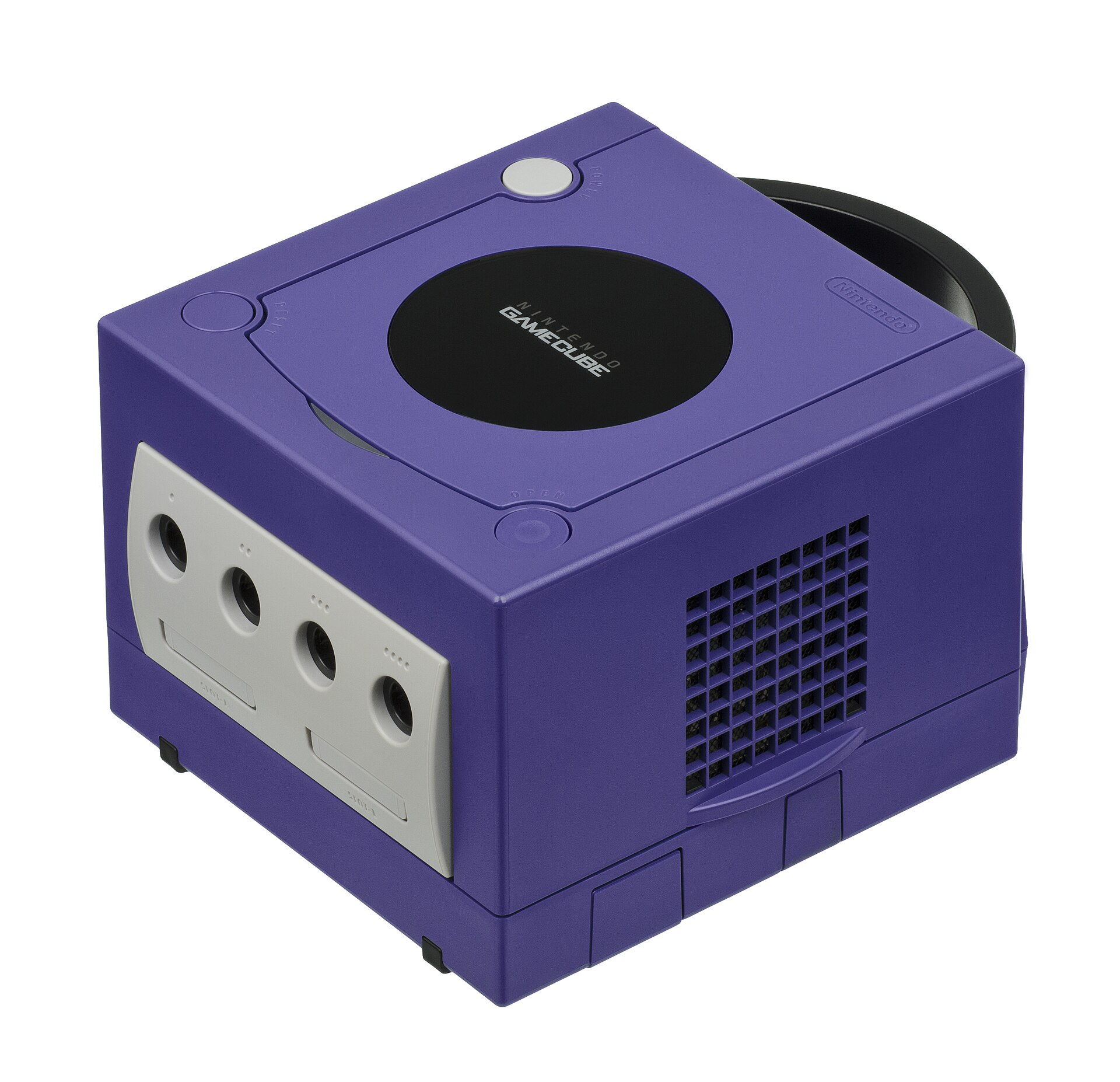
Identification
| Field | Value |
|---|---|
| Manufacturer | Nintendo |
| Release | 2001 (JP/US), 2002 (EU) |
| Generation | 6th |
| Models | DOL-001 (digital port) · DOL-101 (no digital port) |
| Video output | Composite, S-Video, native RGB (SCART), Component (DAC), digital (DOL-001) |
| Region / lockout | JP / US / EU |
| Media | 8 cm mini-disc (~1.5 GB) |
Architecture (detail)
| Block | Chip | Clock | Notes |
|---|---|---|---|
| CPU | IBM PowerPC Gekko (750CXe base) | 485 MHz | "paired singles" SIMD |
| GPU | ATI/ArtX Flipper | 162 MHz | integrates 3 MB of 1T-SRAM (framebuffer/textures) |
| RAM | 24 MB 1T-SRAM (main, 324 MHz) + 16 MB DRAM (aux/audio) | Low latency | |
| Media | 8 cm mini-DVD (~1.5 GB) | Matsushita drive |
The digital port (Digital AV, DOL-001) exposes the raw digital video → the base of the HDMI mods (GCVideo / Carby / GCDual). The DOL-101 removed it. On the audio side, a dedicated DSP (Macronix) handles 64 ADPCM voices and Dolby Pro Logic II (surround on some games).
Connectivity & accessories
- GBA link (link cable): a Game Boy Advance acts as a controller + 2nd screen (Four Swords Adventures, Metroid Prime, The Wind Waker, Animal Crossing + e-Reader) — a GameCube signature.
- Game Boy Player: a bottom add-on to play GB/GBC/GBA games on TV (needs a boot disc; the homebrew GBI/Swiss replaces it more usefully).
- Broadband / Modem Adapter (Serial Port 1): online play (Phantasy Star Online) and LAN (Mario Kart: Double Dash!!, 1080°, Kirby Air Ride).
- Controllers: an octagonal-gate stick (a Smash icon), the WaveBird (RF wireless, no rumble), DK Bongos.
- Panasonic Q (Japan): a GameCube + DVD player in a Panasonic stainless case.
Common faults
| Symptom | Likely cause | Lead |
|---|---|---|
| Won't read discs | Worn optical drive | GC Loader ODE (SD), or replace the drive |
| No digital image | DOL-101 model (no digital port) | Use a DOL-001 for the HDMI mods |
| Memory card not read | Contacts | Cleaning |
Step-by-step disassembly procedures ✅
9 procedures transcribed from the iFixit guides, with difficulty and estimated time.
| Procedure | Difficulty | Time |
|---|---|---|
| Disassembling Nintendo GameCube Exterior Case | Very easy | 1-2 minutes |
| Installing Nintendo GameCube Motherboard | Moderate | 20 to 30 minutes |
| Installing Nintendo GameCube Optical Drive | Moderate | 30 to 45 minutes |
| Turning up the Laser Power | Easy | — |
| Repairing Nintendo GameCube Cleaning the Cooling Fan | Moderate | 7 Minutes |
| Repairing Nintendo GameCube Front and Back Panel | Easy | 5 Minutes |
| Repairing Nintendo GameCube Optical Drive Assembly | Moderate | 30 minutes |
| Repairing Nintendo GameCube Optical Drive Assembly | — | — |
| Nintendo GameCube Teardown | Moderate | — |
Disassembling Nintendo GameCube Exterior Case
Removing the external case will allow you access to the GameCube's internal parts.
- Flip unit over and locate the four screws shown in the second photograph.
- Remove four corner screws located on the underbelly of the unit using a 4.5 mm Gamebit screwdriver.
- Flip unit over and locate the four screws shown in the second photograph.
- Remove four corner screws located on the underbelly of the unit using a 4.5 mm Gamebit screwdriver.
Installing Nintendo GameCube Motherboard
This guide will teach you how to remove the existing GameCube motherboard and replace it with a new one.
- With the Optical Drive Assembly removed, your GameCube should now look like this.
- Remove the 6 screws on the heat sink with a #1 Phillips screwdriver.
- Gently lift the motherboard from base.
Installing Nintendo GameCube Optical Drive
This Guide will teach you how to replace a faulty optical drive with a new one.
- Carefully slide the lens assembly out from the optical drive assembly.
- Insert new optical drive into the GameCube the same way the old one was taken out.
Turning up the Laser Power
This fixes the problem of game discs not being read properly.
- Rotate the assembly so that the green circuit board is facing you as shown in the first picture.
- Flip board over so it is oriented as shown in the second picture.
- Using a Phillips #1 Screwdriver, turn the small knob one quarter turn clockwise.
Repairing Nintendo GameCube Cleaning the Cooling Fan
This guide shows how to properly remove and clean the fan. This will help prevent your GameCube overheating.
- Unscrew the two screws holding the fan assembly onto the unit using a Philips #2 screwdriver as shown.
- Carefully unplug the tan connector from the socket. Do not pull on the wires (as shown), but pull on the connector itself.
- Unscrew the two screws holding the fan assembly onto the unit using a Philips #2 screwdriver as shown.
- Carefully unplug the tan connector from the socket. Do not pull on the wires (as shown), but pull on the connector itself.
Repairing Nintendo GameCube Front and Back Panel
Removing these panels allows further access to the GameCube's components.
- Depress clips and remove back panel as shown.
- Carefully unclip controller ports in the front of the unit.
- A ribbon cable is still attached to the unit. Do not disconnect this cable (outlined in yellow).
- Carefully unclip controller ports in the front of the unit.
- A ribbon cable is still attached to the unit. Do not disconnect this cable (outlined in yellow).
Repairing Nintendo GameCube Optical Drive Assembly
This guide will teach you how to disassemble the GameCube Optical Drive Assembly for the purpose of accessing the Optical Drive and the laser.
- At this point, your optical drive assembly should be separate from your GameCube and look like this.
- Flip drive assembly over and remove 8 screws as shown.
- Remove the metal plate, being careful not to disturb the brown ribbon cable.
- Remove the blue wire
- Using a #1 Phillips Screwdriver, remove 4 screws
- The fourth screw is located behind the screwdriver in the third picture
- Flip out circuit board as shown, being careful not to sever the red wire or the white ribbon cable.
- Red Wire
- Ribbon Cable
- Use a flathead screwdriver to carefully release the four plastic clips holding the drive assembly together.
- The last clip can be rather hard to find. Use a screwdriver as shown in the third image to get behind the plastic to release the last clip.
- Lift metal plate off of drive assembly, again being careful not to sever the two wires still attached to the two halves of the drive assembly.
- Next, flip and rotate the drive assembly so that it resembles the one in the third picture.
- Using the screwdriver, release two more clips around the back half of the drive assembly.
- The last clip doesn't need to be released, the top half of the drive assembly will slide away from the lower half.
- Finish removing the top half of the drive assembly, be careful as this piece is where the two wires (in yellow) that should not be removed are attached to (unless you want to do some soldering).
Repairing Nintendo GameCube Optical Drive Assembly
- At this point, your optical drive assembly should be separate from your GameCube and look like this. Flip drive assembly over and remove 8 screws as shown. Remove the metal plate, being careful not to disturb the brown ribbon cable.
- Remove the blue wire Using a #1 Phillips Screwdriver, remove 4 screws The fourth screw is located behind the screwdriver in the third picture
- Flip out circuit board as shown, being careful not to sever the red wire or the white ribbon cable. Red Wire Ribbon Cable
- Use a flathead screwdriver to carefully release the four plastic clips holding the drive assembly together. The last clip can be rather hard to find. Use a screwdriver as shown in the third image to get behind the plastic to release the last clip.
- Lift metal plate off of drive assembly, again being careful not to sever the two wires still attached to the two halves of the drive assembly. Next, flip and rotate the drive assembly so that it resembles the one in the third picture.
- Using the screwdriver, release two more clips around the back half of the drive assembly. The last clip doesn't need to be released, the top half of the drive assembly will slide away from the lower half.
- Finish removing the top half of the drive assembly, be careful as this piece is where the two wires (in yellow) that should not be removed are attached to (unless you want to do some soldering).
Nintendo GameCube Teardown
The Nintendo GameCube launching 2001 was the second most powerful gaming console of its time, though it didn't feature any other multimedia capabilities than playing games. It was my first stationary gaming device and I still appreciate it, because a lot of good games like Zelda: The WindWaker and the best version of Resident Evil 4 have their homes on this platform. The unit disassembled in this teardwon is a PAL one. That's it. enjoy the teardown!
- Before you can even think of disassembling any Nintendo device you have to face the same problem with every console except the Wii: the screws of the enclosure. And the most tricky fact of these screws is their type because this is not a reasonable standard screw.
- These four screws I'm talking about are a compound of a flat plate with a thicker convex layer with six notches in the brass.
- This bit is a Nintendo Reduced E Series bit size 8. Found at http://eazypower.com/shop/nintendor-tee-starr-screw-remover-14.html
- I couldn't find anything suitable in the internet, so I built one on my own in this way:
- Using a steel rod of about 8 mm diameter.
- I tried to mill three teeth with equivalent distance around the boundary of one end of the rod with an angle grinder. After that I drilled a hole perpendicularly in the center of the rod. Taddaah... a working screwdriver!
- Now let's begin the Teardown.
- Make sure to have a game disc inserted to avoid damaging the lens. Flip the unit upside down and remove the screws sitting in the four holes with your possibly self-made screwdriver. Don't remove the enclosure yet!
- Turn the device on its stands again, now lift the top case off. It'll come up easily.
- Unsnap the controller port cover and the rearmost I/O-cover by unsnapping the two snaps on the sides of each cover. Don't remove the controller panel yet.
- Then remove the heatsinks of the memory card slots (necessary step).
- Now start removing the 'normal' Phillips #0 screws.
- Start by removing the fan assembly.
- then unscrew the 12 visible screws on the edging of the now not any more so cubeshaped GameCube.
- Now you can lift the drive assembly up. You maybe have to loosen it a bit with a screwdriver or a heavy duty spudger.
- The mainboard is now visible.
- Now remove the heatsink. unscrew the six screws holding it.
- now use anything flat and durable to carefully lift up the heatsink by puttig it under the aluminium and using it gently as a lever.
- If there are thermal pads remainig on the processors and/or ram chips, remove them with a plastic spudger.
- Now disconnect the controller port panel connector by lifting and jiggling it carefully. It should come off easily.
- 24 MB MoSys 1T-SRAM
- ATI 'Flipper' GPU, 162 MHz with 3 MB 1T-SRAM embedded within the die
- IBM 'Gekko' CPU, 486 MHz (PowerPC 750CXe-based core)
- Connectors (2nd pic):
- 'Hi Speed Port'
- 'Serial Port 1'
- 'Serial Port 2'
- 24 MB MoSys 1T-SRAM
- ATI 'Flipper' GPU, 162 MHz with 3 MB 1T-SRAM embedded within the die
- IBM 'Gekko' CPU, 486 MHz (PowerPC 750CXe-based core)
- Connectors (2nd pic):
- 'Hi Speed Port'
- 'Serial Port 1'
- 'Serial Port 2'
Source, licence and scope
iFixit guides, under Creative Commons BY-NC-SA — attribution, non-commercial, share-alike. Only the text is reproduced; the step photos stay on iFixit. ⚠️ These guides target the model named in the title: on another revision, the screws and the order of removal may differ.
Procedure — a dead console, step by step ✅
What this adds
Ordered for a console, not for an arcade board: what kills these is almost never the CPU. It is, in real order, the power supply, the capacitors, the drive or the cartridge slot, and only then the logic. → PCB diagnosis
1. The power supply. Two cases, depending on the machine. External brick: ⚠️ read the marking on the machine, next to the socket, and check the adapter against it — voltage and polarity. A centre-negative machine fed centre-positive loses its fuse, sometimes its regulator; do not trust a third-party label or a generic tip. Internal supply (the machine plugs straight into the wall): mains is inside the shell. Unplug, wait, and confirm the large capacitors are discharged before touching the board. Either way, measure under load: a failing supply holds its voltage until it is asked for current.
2. The fuse. Many of these machines have one right behind the socket — it is the part designed to die. Test it in continuity, out of circuit. A fuse that blows again is a short, not a fuse problem.
3. Capacitors. On most machines of this age this is the default suspect rather than a last resort — leaking SMD electrolytics eat the tracks underneath before they give any other sign. ⚠️ Not all of them are like that: some carry very few and are not recapped on principle. Read what this page says about it before reaching for the iron. → Recap
4. The drive. On this machine it is the dominant failure point. In order: does the tray move, does the disc spin, is the lens clean (cotton bud, isopropyl alcohol, no pressure), do the rails slide freely. A laser that no longer reads gets replaced; the gain pot is not something to tweak blind — that is the move that finishes off a laser that was still good.
5. Video output. Isolate the machine from the display: another cable, another TV, another input. A sizeable share of "dead consoles" are a dead cable, or a display that will not lock onto what this machine outputs — see the video section of this page for what that is.
6. Still nothing. Now, and only now, the logic: rails on the board, reset, clock, bus. → PCB diagnosis
Capacitor list (NTSC logic board, per CXX reference) ✅
Source: Console5 TechWiki. NTSC logic board (the PAL differs slightly):
| Ref | µF | V |
|---|---|---|
| C1, C3 | 33 | 25 |
| C2 | 220 | 25 |
| C115, C116, C118 | 10 | 16 |
| C155, C156 | 220 | 6.3 |
The DC/DC boards (converters) and the external PSUs have many variants (Mitsumi, Sharp, TDK, Zebra…) with their own lists — see Console5 for your reference.
Popular mods — what to buy, where, procedures
Key buying fact: the digital port
The HDMI output plugs into the digital AV port found only on DOL-001 consoles. DOL-101 (late revision) has NO such port → for HDMI you must add it back ("Digital Port Upgrade" mod) or use component/RGB. Procedures from ConsoleMods (CC-BY-SA).
Video — HDMI (perfect image, DOL-001)
- All of it is built on GCVideo: GCHDMI, Carby (HDMI), GCDual (PixelFX, HDMI + Component), EON GCHD MKII, GCPlug, Pluto IIx, HDPrism, Retro GEM adapters. Mostly plug-and-play 🟢 (into the digital port). → GameCube digital page.
- Analog RGB: native on PAL/EU GameCubes (European DOL-001) → an RGB-SCART cable, no mod. NTSC GCs do not output analog RGB (composite/S-Video only) → use the digital port (GCVideo) or official component. (Nothing to solder: it's a cable + region matter, not a solder point.)
Games on SD — ODE (replace the GOD/DVD drive)
- GC Loader PNP or CubeODE: replace the optical drive with an SD card. → GC Loader page.
- SD2SP2 / SD Gecko: SD via a serial port (Serial Port 2 under the hatch, or Memory Card) — slower, mainly to launch Swiss/homebrew and load games from SD.
Run homebrew / region-free — softmod
- PicoBoot: flash the IPL (boot) via a Raspberry Pi Pico (~5 wires soldered to board test points) → the console boots straight into Swiss from an SD card. Open-source modchip, ~€5.
- Swiss: the homebrew swiss-army knife — region-free, forces 480p, launches games from SD/ODE,
patches. → Softmods. Open-source tool archived locally (
files/tools/gamecube/swiss-gc).
Recap / audio
- Replacing Capacitors (cap kit) on affected models. Digital Audio (SPDIF) Mod for optical audio.
Preservation & softmod
- The 8 cm mini-DVD uses a proprietary format (BCA/"barcode" track, non-standard sectors) unreadable by a PC drive → hence the value of ODEs and dumping via Swiss (broadband cable / SD).
- Softmod with no hardware via save exploits (SD Media Launcher, game exploits) that
launch Swiss — the GameCube toolbox (DVD-R boot, ODE, region, progressive/480p forcing,
dumping). → open-source tool archived here (
swiss-gc). - Emulation: very mature (Dolphin, HD + widescreen).
Photos / assets
(To add: board, DOL-001 digital port, drive, AV outputs.)
Advanced repair
Optical drive (laser / gain pot) or an ODE (GC Loader) replacement; recap. Methods: ODE (GC Loader) · Recap · PCB fault-finding.
Sources & attribution
- Wikipedia — GameCube — CC-BY-SA — https://en.wikipedia.org/wiki/GameCube
- Console5 TechWiki — GameCube (logic board/DC-DC/PSU per-reference recap BOM) — https://wiki.console5.com/wiki/GameCube
- ConsoleMods — GameCube (HDMI, GC Loader, RGB) — to reference — https://consolemods.org/wiki/GameCube
Image:
-
gamecube-console.jpg— Evan-Amos, public domain — https://commons.wikimedia.org/wiki/File:Nintendo-GameCube-Console-FL.jpg

Review & corrections
How this space is used
Spotted a wrong value, an outdated procedure, a chip reference that does not match your board? Say so here, with what you observed (model, board revision, serial number, measurement). Every report is cross-checked against a source before anything changes — an unverifiable correction is published as “reported by …, not cross-checked” rather than silently applied.
Reading is open to everyone; posting requires signing in with Discord. Reports from the wiki's declared reviewers are handled first; anyone else's are read too, but go through a human before anything is changed.