Atari 2600 (VCS)
The console that launched mass home gaming (Atari VCS, 1977). 8-bit, 128 bytes of RAM, everything rests on the famous TIA. RF output stock → the composite/AV and RGB mods are the great classics.
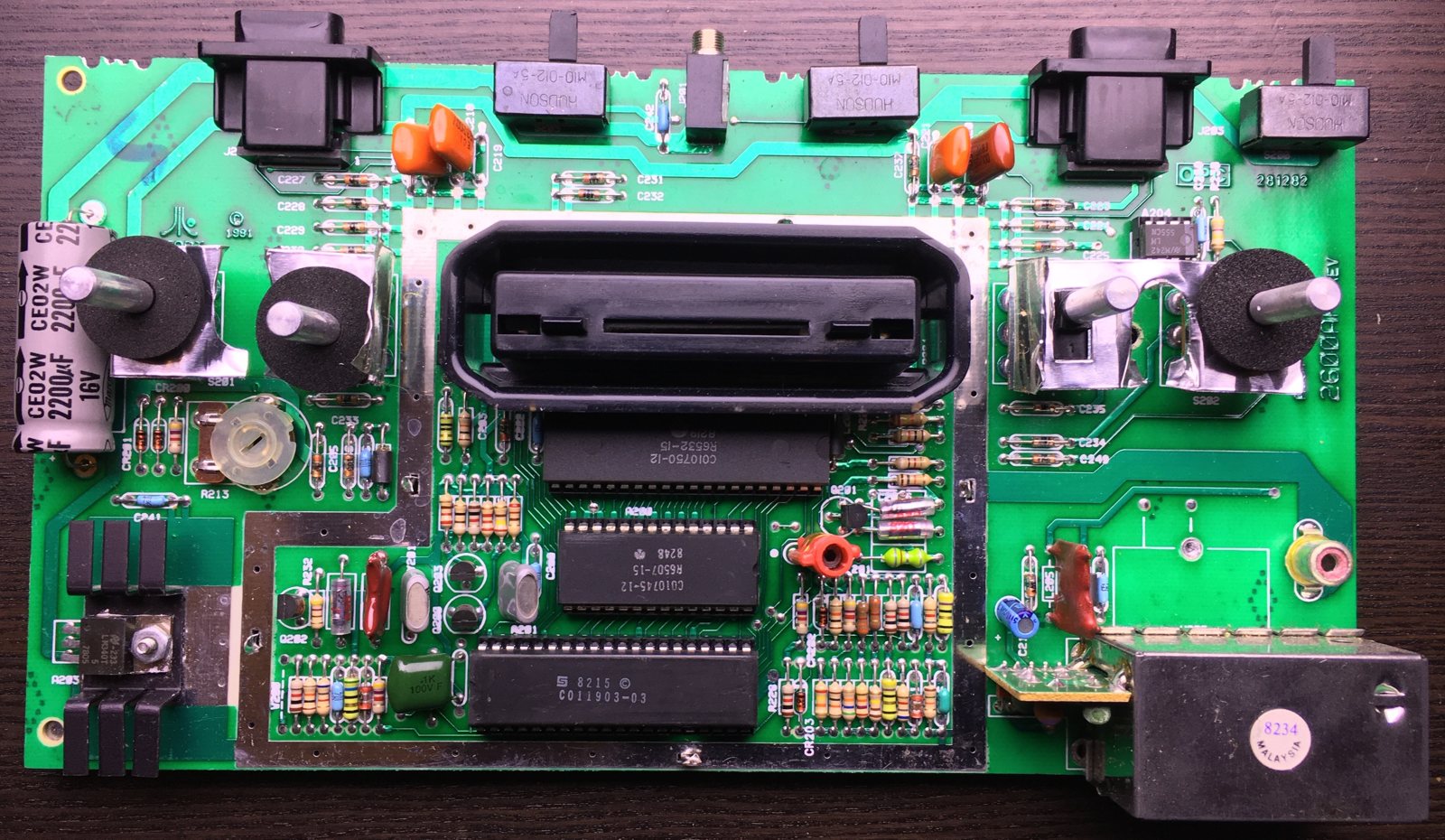
Identification
| Field | Value |
|---|---|
| Manufacturer | Atari |
| Release | 1977 |
| Generation | 2nd (8-bit) |
| Revisions | Heavy/Light Sixer · 4-switch · Vader (2600A) · 2600 Jr |
| Native video output | RF (composite/RGB via mod) |
| Region | NTSC / PAL / SECAM |
| Media | Cartridge |
Architecture
| Block | Chip | Clock | Role |
|---|---|---|---|
| CPU | MOS 6507 (6502 in a 28-pin package) | ~1.19 MHz | 13 address lines → 4 KB addressable per bank |
| Video / sound | TIA | "race the beam": no framebuffer, the CPU composes the image line by line; 2 audio voices | |
| RAM + I/O | RIOT (MOS 6532) | 128 bytes of RAM + timer + controller ports | |
| Media | Cartridge (bank-switching to exceed 4 KB) |
A console with no screen memory: the program must sync the CPU with the TV scan on every line ("racing the beam") — the most demanding programming of its generation.
Common faults
| Symptom | Likely cause | Lead |
|---|---|---|
| Poor RF image / snow | RF output | Composite/AV mod |
| Cartridge not read | Connector oxidation | Cleaning |
| Flaky switches | Worn switches | Clean / replace |
| No image | Power, TIA, contacts | Diagnosis |
(Very few capacitors: recap secondary.)
Original service manual ✅
Manufacturer manual archived locally. It typically carries the schematics, the block diagram, the expected voltages and waveforms, the parts list and the disassembly procedures — the reference when a symptom matches no known fault.
- Atari 2600 — field service manual — PDF
- Official Atari schematics: CX2600 / CX2600A (NTSC) — PDF · CX2600P (PAL) — PDF
- SECAM version: schematic — PDF · board layout — PDF
- TIA 1A — logic diagram — PDF
- Technical documentation — PDF
Use the schematic for YOUR region
NTSC, PAL and SECAM share neither the same crystal nor the same video stage. The CX2600P schematic is the PAL machines' one, and the SECAM version has its own board — hence the separate layout. Picking the wrong schematic sends you looking for a part that does not exist on the board in front of you.
Status
A manufacturer document with no explicit licence, kept for preservation (machine long out of production). Source: Internet Archive.
Step-by-step disassembly procedures ✅
1 procedures transcribed from the iFixit guides, with difficulty and estimated time.
| Procedure | Difficulty | Time |
|---|---|---|
| Atari 2600 Teardown | Moderate | No estimate |
Atari 2600 Teardown
Welcome to day three of our week of game console teardowns. So far we've taken apart the Magnavox Odyssey 100 and the RCA Studio II; the Atari 2600 is next! We partnered with PC World for this teardown to bring you a peek into another staple of game console history. Originally labeled as the Video Computer System (VCS), the Atari 2600 was released in 1977. By that time, microprocessor-based hardware had been popularized with the Fairchild Channel F, and the VCS was Atari's first foray into that technology. The system was originally released with all six switches on the front of the console, however, the console was redesigned in 1980 with only four of the switches on the front, and the other two on the back. The console featured here is a post-1980 model.
- Atari 2600, with AC adapter and iconic joystick controller.
- Does the 2600 have a hardwood finish? You are correct sir!
- Video game consoles these days may not have a sense of home decor, but some computer companies still believe in the aesthetics of wood paneling.
- At its release, the 2600 sold for $199. In today's coin, that's $696. In comparison, the launch model of PlayStation 3 cost only $599. Prices are coming down!
- As soon as users figured out that the Atari 2600 could play more games than just Pong, the 2600 became massively successful. It went from selling 250,000 consoles in 1977 to 1 million units in 1979.
- From its release in 1977 until 1983, the Atari 2600 was officially called the Video Computer System, in response to Fairchild Semiconductor's Video Entertainment System. The console was later renamed after its model number, CX2600.
- Instead of following the trend of building a limited number of games into the system like the Magnavox Odyssey 100, the Atari 2600 used removable cartridges to store games like Space invaders, Pac-Man and Pitfall!
- Each player could select the difficulty of the game they were playing by simply flipping a switch from "A" to "B". Which one was harder is anyone's guess.
- There are four screws holding the upper and lower case together.
- Hmm, these screws in the back are at an odd angle: almost 30 degrees off of vertical! Strange.
- With such a large console, there must be a ton of awesome components inside...
- ...Or not. Seriously? That's it? The case design team must have wanted to give lots of breathing room to the motherboard team, just in case. (Actually this is the third version of the internal hardware, the first took up much more of the case.)
- Jay Miner was able to integrate the display and sound chip into a single IC, thereby reducing the footprint of the motherboard, but the case size still seems rather hyperbolic.
- With a design that is unseen in just about any other electronic device, the motherboard is propped up and sits at an angle of 30 degrees inside the Atari. Now those case screws make sense!
- Finally, cables that are not soldered to the board! (Take note, Studio II.) The RCA cable is easily removed.
- The motherboard easily lifts out, as there are no additional screws or clips holding it in place. The only thing securing it down were the angled screws we removed from the outer case.
- The motherboard measures 9.75" x 5.25" and the lower case measures 13.75" x 9.75".
- The case of the 2600 is 2.6 times larger than the motherboard!
- The motherboard of the 2600 is dominated by an ominous metal box, likely the EMI shield covering the ICs.
- Our efforts to access the brain of the Atari are temporarily thwarted by four metal tabs.
- A few short twists with pliers and the EMI shield lifts free.
- Atari gets a +1 on repairability for not soldering the shield to the motherboard, as some recent manufacturers have done.
- Brains!
- The Atari 2600 boasts:
- 1.19MHz 8-bit processor
- 128 bytes RAM
- 192 x 160 pixel resolution
- 128 colors, with max 4 colors per line
- 2 channel mono sound
- Unlike most earlier consoles -- where the games were stored on internal chips -- the Atari 2600 stored games in Read Only Memory (ROM) chips housed in external cartridges. This allowed for a potentially infinite number of playable games for the console.
- The top two chips are the 6532 Ram-I/O-Timer (RIOT) chip and MOS Technology's 6507 CPU (a slimmer version of the more popular 6502). By the current revision, they were manufactured by Synertek and Rockwell, respectively.
- Atari's custom chip, the Television Interface Adapter (TIA) is the moneymaker of the 2600, as it allowed for multiple colors, increased graphic capabilities, and sound.
- Because memory was so expensive during the 2600's design, the video processor has no external RAM. As a result the CPU must send video data to the TIA one line of video at a time.
- There are six components of video that the TIA can create: The playing field, Two sprites (8 pixel lines), a "ball" (single pixel), and two "missiles" (two pixel lines). Combinations of these elements allowed for the complex video games witnessed in the 2600.
- With the EMI shield removed, all the components of the motherboard are visible.
- Color tint adjustment
- Sound tuner
- RF modulator
- Cyan Engineering TIA custom chip (manufactured by Motorola)
- MOS Technology 6532 RIOT (manufactured by Synertek)
- MOS Technology 6507 CPU (manufactured by Rockwell)
- Voltage regulator (manufactured by Texas Instruments)
- The back of the Atari 2600 Motherboard has exactly nothing interesting on it, except a great appreciation for through-hole soldering and hand drawn circuits.
- This model was revision 13. How lucky!
- Behold the Atari in all five of its parts!
- We give the Atari 2600 a big plus for repairability. Every component is attached via through-hole solder, so replacing a burnt out resistor or IC is quite feasible.
- We're sad to say that we don't have parts for the Atari 2600, but we do have a brand new game console parts store to help keep your (slightly more modern) consoles running.
- Keep an eye on our teardown page or blog for a detailed look at another retro game console tomorrow!
Source, licence and scope
iFixit guides, under Creative Commons BY-NC-SA — attribution, non-commercial, share-alike. Only the text is reproduced; the step photos stay on iFixit. ⚠️ These guides target the model named in the title: on another revision, the screws and the order of removal may differ.
Procedure — a dead console, step by step ✅
What this adds
Ordered for a console, not for an arcade board: what kills these is almost never the CPU. It is, in real order, the power supply, the capacitors, the drive or the cartridge slot, and only then the logic. → PCB diagnosis
1. The power supply. Two cases, depending on the machine. External brick: ⚠️ read the marking on the machine, next to the socket, and check the adapter against it — voltage and polarity. A centre-negative machine fed centre-positive loses its fuse, sometimes its regulator; do not trust a third-party label or a generic tip. Internal supply (the machine plugs straight into the wall): mains is inside the shell. Unplug, wait, and confirm the large capacitors are discharged before touching the board. Either way, measure under load: a failing supply holds its voltage until it is asked for current.
2. The fuse. Many of these machines have one right behind the socket — it is the part designed to die. Test it in continuity, out of circuit. A fuse that blows again is a short, not a fuse problem.
3. Capacitors. On most machines of this age this is the default suspect rather than a last resort — leaking SMD electrolytics eat the tracks underneath before they give any other sign. ⚠️ Not all of them are like that: some carry very few and are not recapped on principle. Read what this page says about it before reaching for the iron. → Recap
4. The cartridge connector. Cartridge contacts with isopropyl alcohol, never an abrasive eraser: it takes the gold plating off and the problem comes back worse. On the machine side, inspect the slot pins — splayed, bent or oxidised — and check continuity between slot and board.
5. Video output. Isolate the machine from the display: another cable, another TV, another input. A sizeable share of "dead consoles" are a dead cable, or a display that will not lock onto what this machine outputs — see the video section of this page for what that is.
6. Still nothing. Now, and only now, the logic: rails on the board, reset, clock, bus. → PCB diagnosis
Bank-switching & homebrew
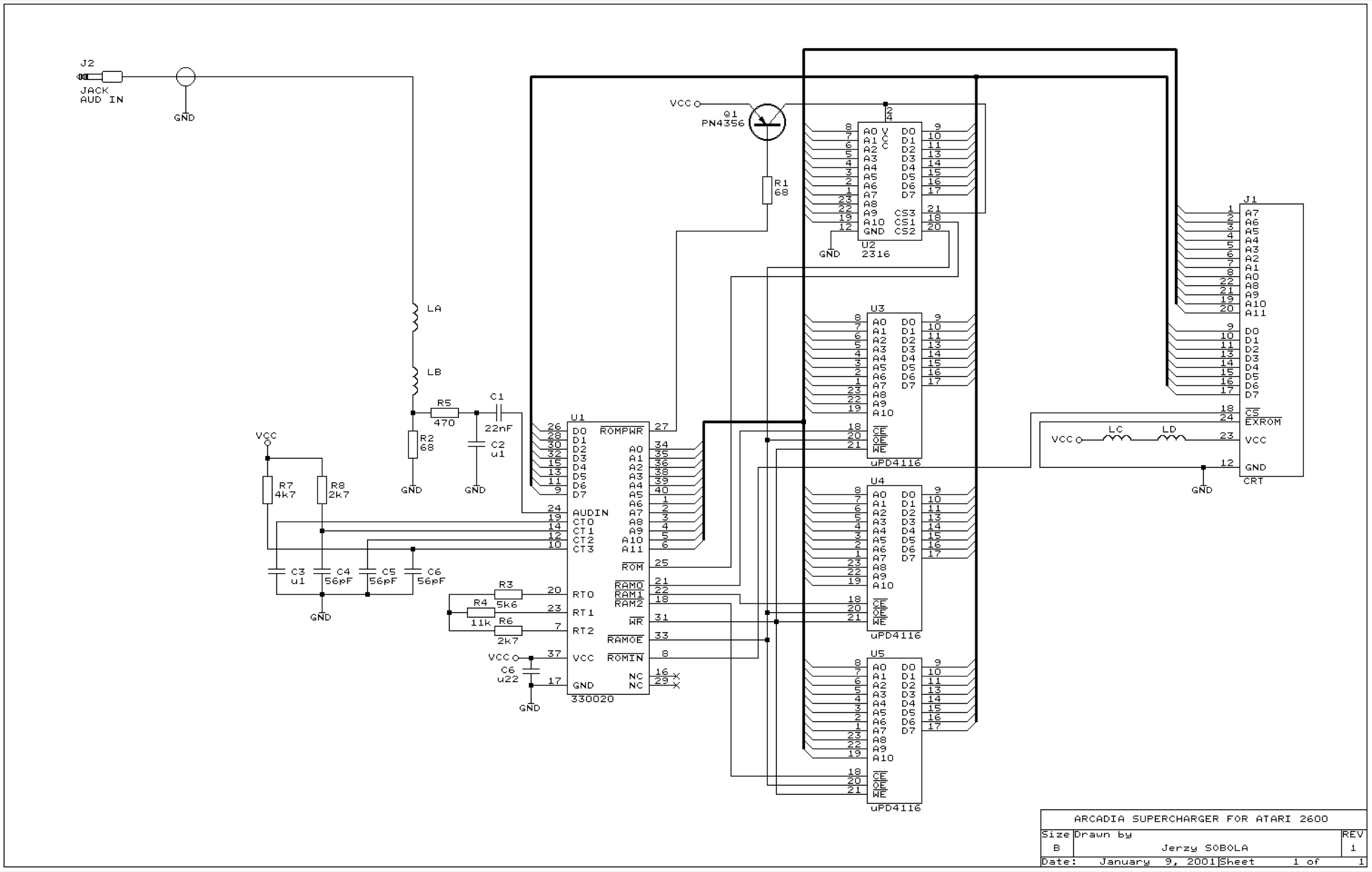
The 6507 addresses only 4 KB: to exceed it, cartridges use bank-switching schemes (F8 = 8 KB, F6 = 16 KB, F4 = 32 KB, FE, E0, 3F…), sometimes with on-cart RAM ("Superchip" scheme). The Starpath Supercharger (1982) loaded games from an audio cassette into 6 KB of RAM. The homebrew scene stays very active (AtariAge still publishes brand-new cartridges) — which feeds the preservation flashcarts (Harmony/Melody).
Popular mods — what to buy, where, how to install
Indicative prices
A cottage/second-hand market → prices and availability move. We name the maker and a known reseller; check at purchase time. Soldering level: 🟢 none · 🟡 keen beginner · 🟠 confident · 🔴 expert.
Play your whole library (flashcart)
-
Harmony / Harmony Encore — a microSD cartridge (AtariAge community). Copy your ROMs to the card and insert it like a game: no soldering 🟢, instant.
- Two versions: Base (games ≤ 8 KB) or Encore (≤ 512 KB, essential for recent homebrew).
- Where: Stone Age Gamer (official reseller), AtariAge. ~ $50–75.
- UnoCart-2600 — an open-source DIY alternative (PCB + STM32 microcontroller): cheaper but build/flash it yourself. For tinkerers.
Get a clean picture (the stock RF is poor)
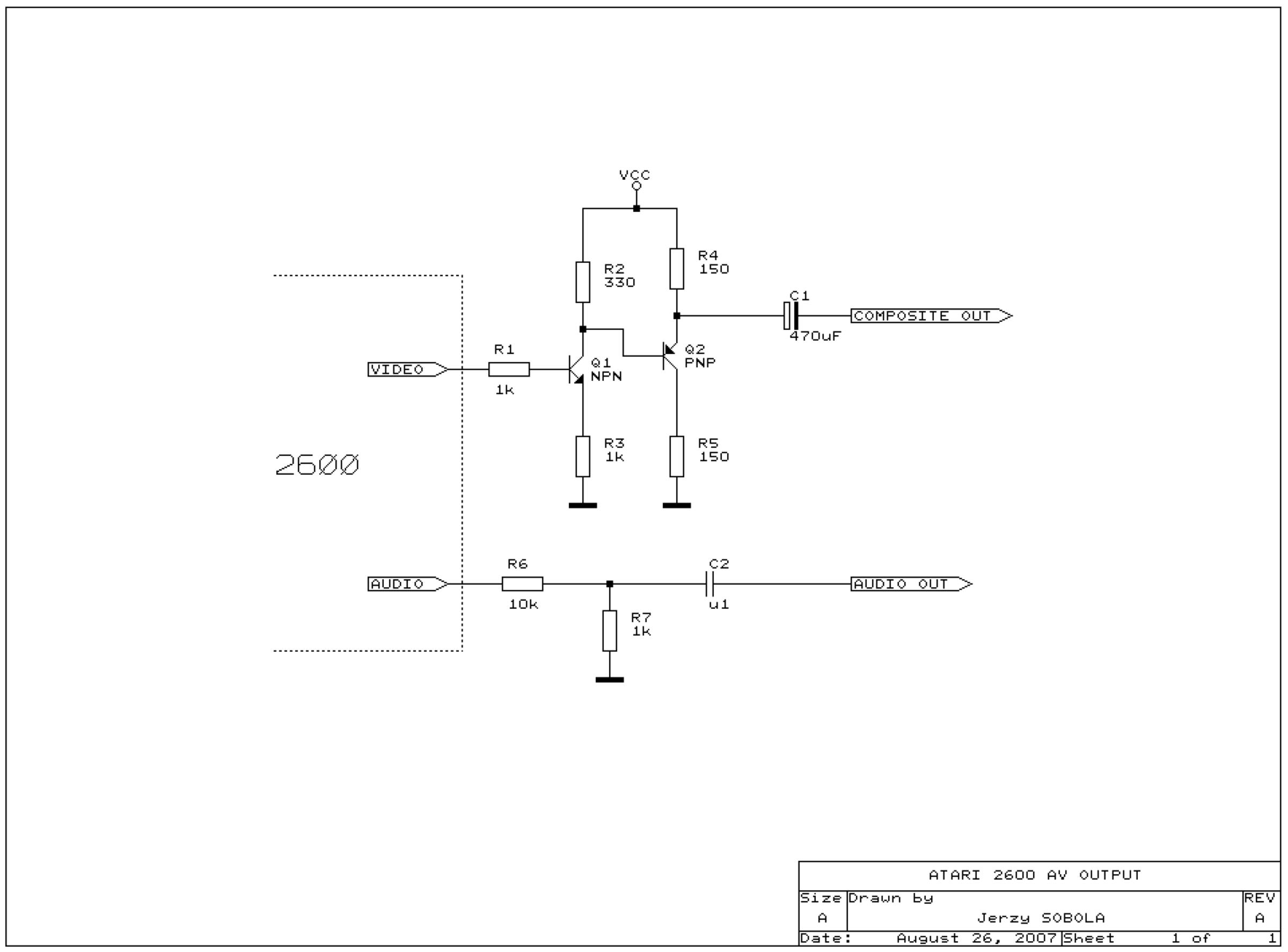
The 2600 already builds its composite picture: the board combines the TIA outputs (sync + 3 luminance + colour) before feeding the RF modulator. Two concrete routes — and the #1 trap: the TIA pinout changes between NTSC and PAL.
TIA pinout — where to tap each signal (NTSC vs PAL) — transcribed from Console5 TechWiki (CC-BY-SA)
The TIA is a 40-pin DIP. Pin 1 = GND, pin 20 = Vcc (+5 V). The video/audio signals are not on the same pins across versions:
| Signal | NTSC (C010444) | PAL (CO11903) |
|---|---|---|
| C.SYNC (composite sync) | pin 2 | pin 2 |
| LUMA OUT 1 | pin 5 | pin 5 |
| LUMA OUT 2 | pin 7 | pin 6 |
| LUMA OUT 0 | pin 8 | pin 7 |
| COLOR OUTPUT (chroma) | pin 9 | pin 9 |
| AUDIO 0 | pin 12 | pin 13 |
| AUDIO 1 | pin 13 | (pin 12 = PAL‑S, no audio) |
⚠️ On PAL pins 6/7/8 and 12/13 are shifted (LUMA 2→6, LUMA 0→7, AUDIO 0→13). A wrong pin = no picture (nothing fried on the output side, but the mod won't work). Tip: these outputs also appear on the legs of the nearby resistors, easier and safer to solder than the chip pins. The two AUDIO 0/1 (NTSC) are mixed to mono (one resistor per channel).
Single-transistor composite mod — full procedure (Vader / 2600A, after Brighty83 via mrpjevans)
The simplest route: don't rebuild the composite from the TIA — buffer the composite already formed at the RF modulator input.
BOM: 1× 2N3904 transistor (NPN, wired as an emitter follower = buffer), 1× 3.3 kΩ, 1× 2.2 kΩ, 2× RCA jacks (yellow video + audio), wire, sleeving.
Solder points — on the RF modulator (labelled pads on the Vader board):
| Wire | Modulator pad |
|---|---|
| Ground (GND) | 1 |
| +5 V | 3 |
| Composite video | 4 |
| Audio | pad "A" (direct audio out) |
Wiring: pad 4 (composite) feeds the input of the 2N3904 emitter-follower (base via a bias resistor, collector to +5 V pad 3, emitter loaded to ground by a resistor — the 3.3 kΩ / 2.2 kΩ provide base bias and emitter load); the buffered output (emitter) goes to the yellow RCA centre. Audio (pad "A") → audio RCA centre. RCA shields → ground (pad 1). Drill the case for the 2 jacks. Install 🟡, ~30–60 min.
⚠️ Pads are Vader-specific: on another revision (Heavy/Light Sixer, 4-switch, Jr) the modulator pads differ — locate the composite point (modulator input) + +5 V/GND on your board; the buffer is unchanged. If there's no clean composite point, tap C.SYNC + LUMA 0/1/2 (+ COLOR) on the TIA directly (table above) into a video amp.
-
2600RGB (Tim Worthington) — the high end: an internal board generating RGB + S-Video + composite (the latter two encoded from RGB), amplified dual-mono audio, 6 palettes, zero latency, NTSC and PAL, nearly all variants, and it replaces the 7805 regulator with a switching one. Materials: iron + desoldering iron, leaded solder, flux, wire, drill + step bits. Per-revision install (6-switch / 4-switch / 2600 Jr / Sears Video Arcade II / Atari 2800).
- Honesty: the exact 2600RGB solder points are not open-licensed — they live in Tim Worthington's official illustrated manual, and ConsoleMods itself links to it rather than copying it. We don't invent them here. Docs + purchase: etim.net.au; variants recap: ConsoleMods: 2600RGB (CC-BY-SA).
Settings / region
- Region NTSC/PAL, 50/60 Hz: depends on the console and games — an added switch, or choose at purchase.
⚠️ Effort recap: Harmony = zero soldering (simplest way to play); composite = light soldering; 2600RGB = advanced soldering. We describe the method, no ROM hosting.
Photos / assets
(To add: Heavy Sixer vs Vader vs Jr, TIA, AV output.)
Advanced repair
Cartridge contacts (No. 1 cause) + joints; few electrolytics. Methods: PCB fault-finding · Recap · Traces & vias.
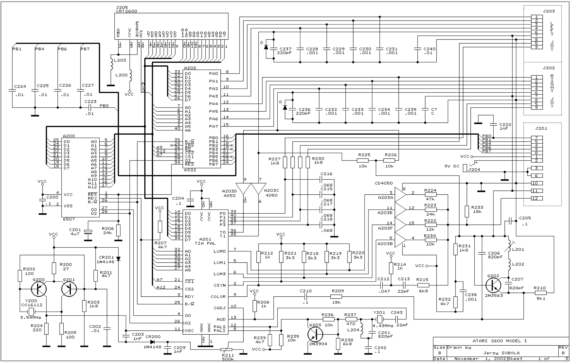
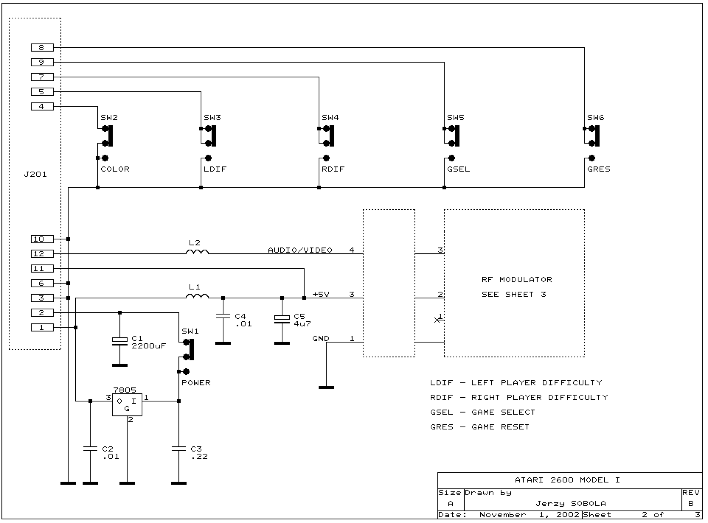
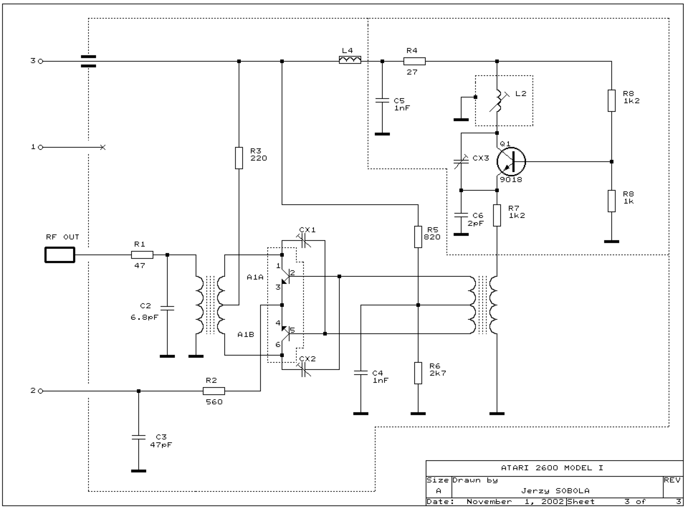
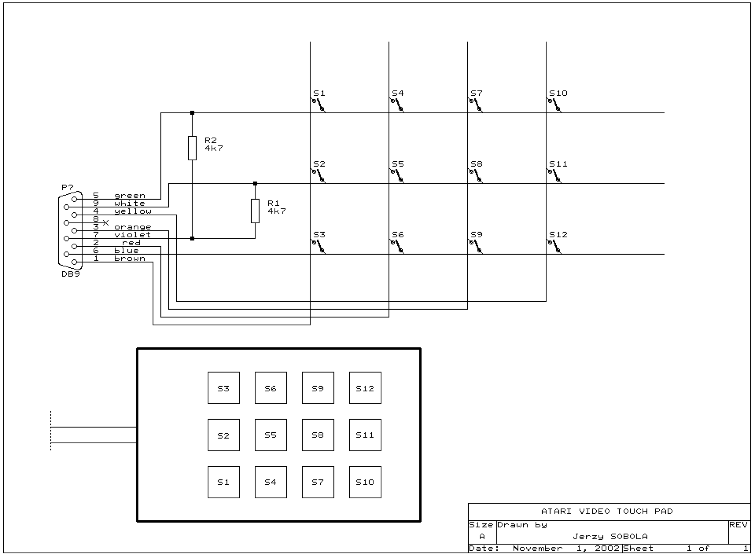
Atari 2600 schematics ✅
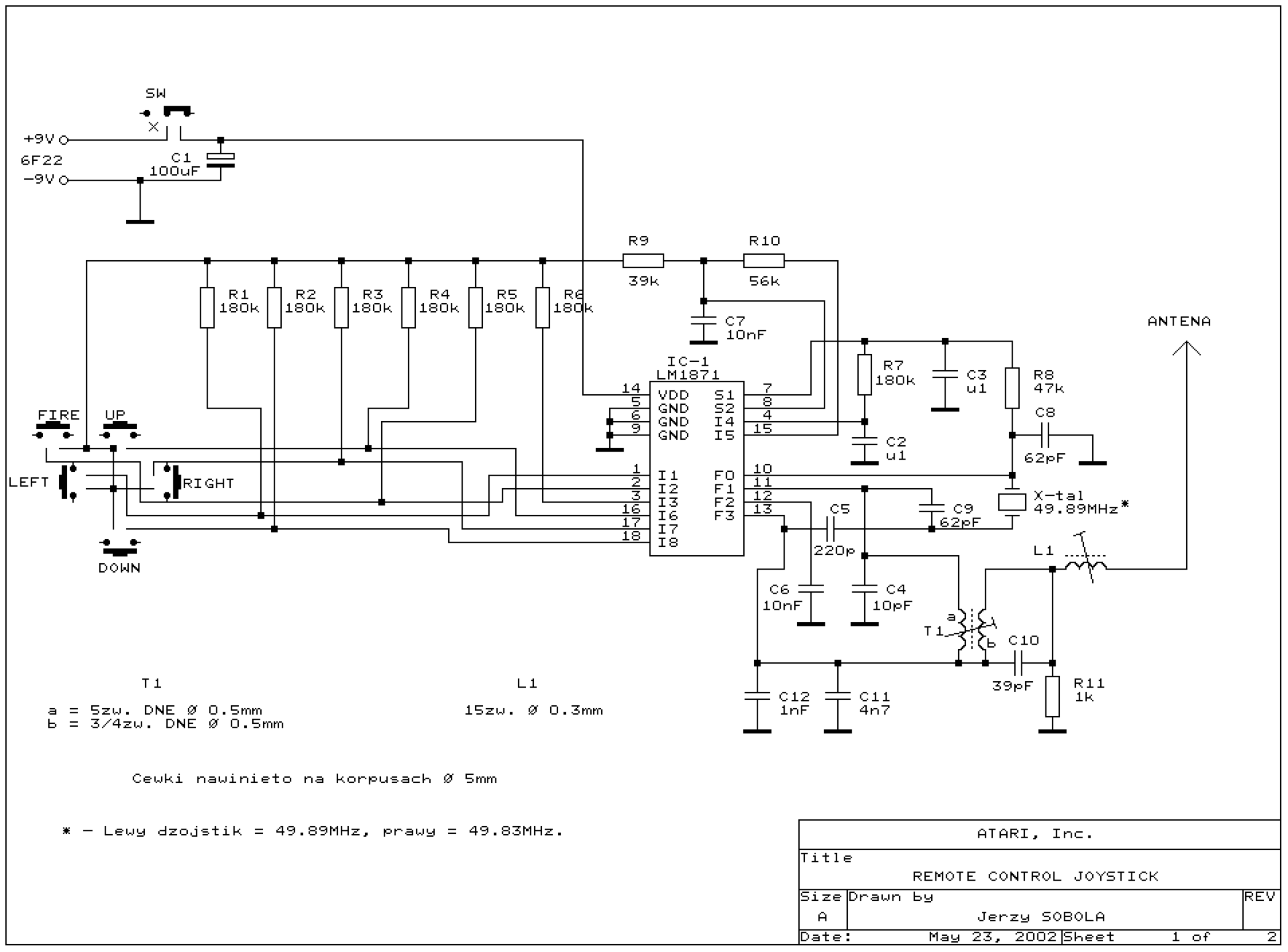
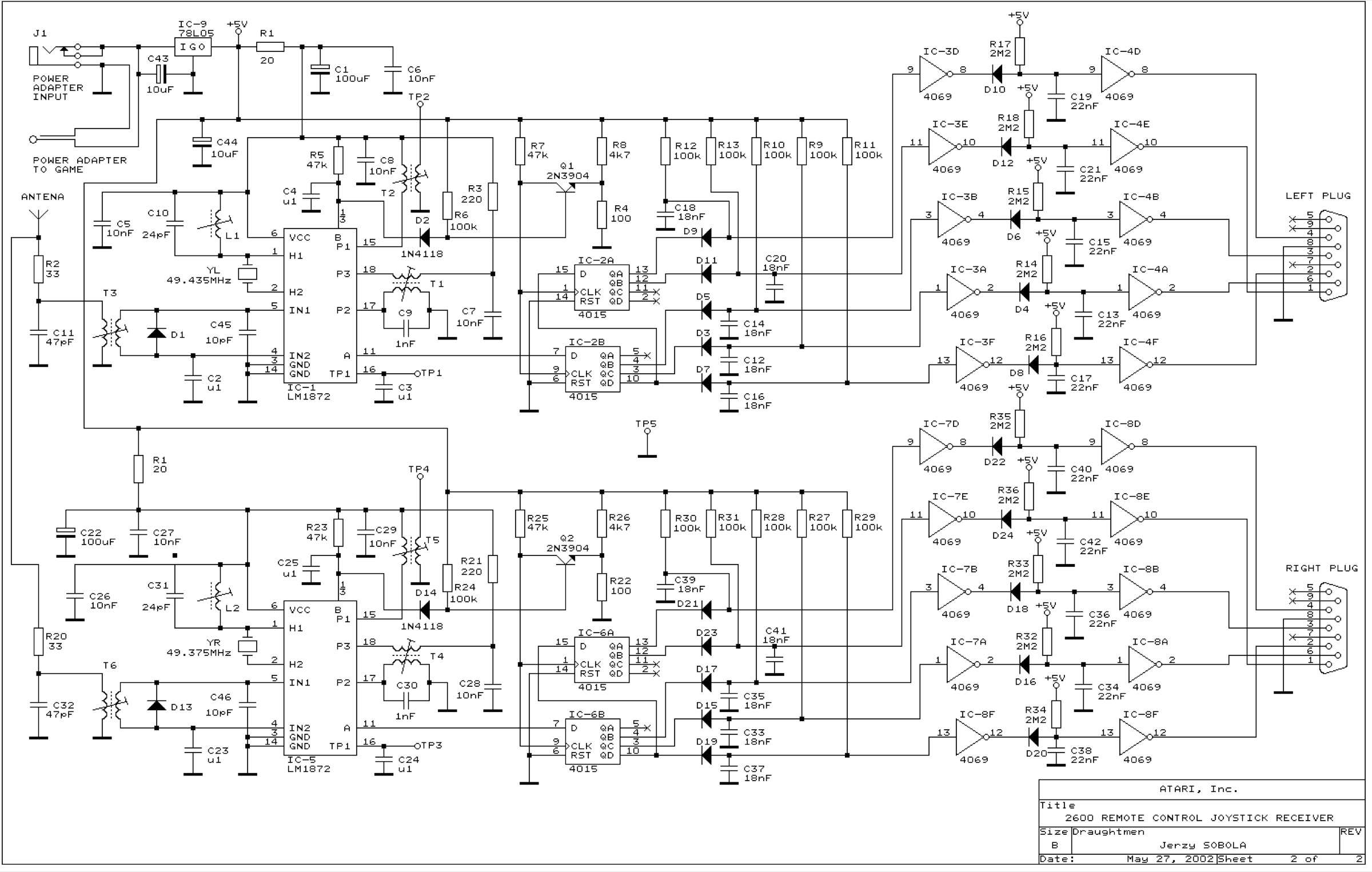
Model I, Jr, PAL and SECAM versions, plus the controller modules.
Credit
Schematics redrawn by Jerzy Sobola, reproduced here for preservation. These are not manufacturer documents: the drawing is his own work.
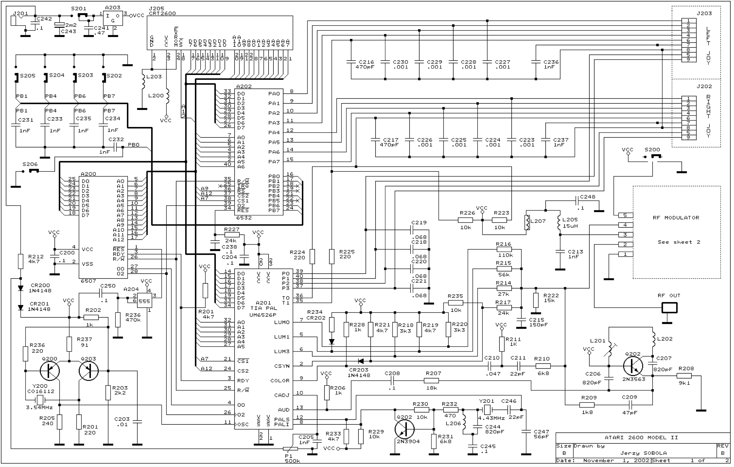
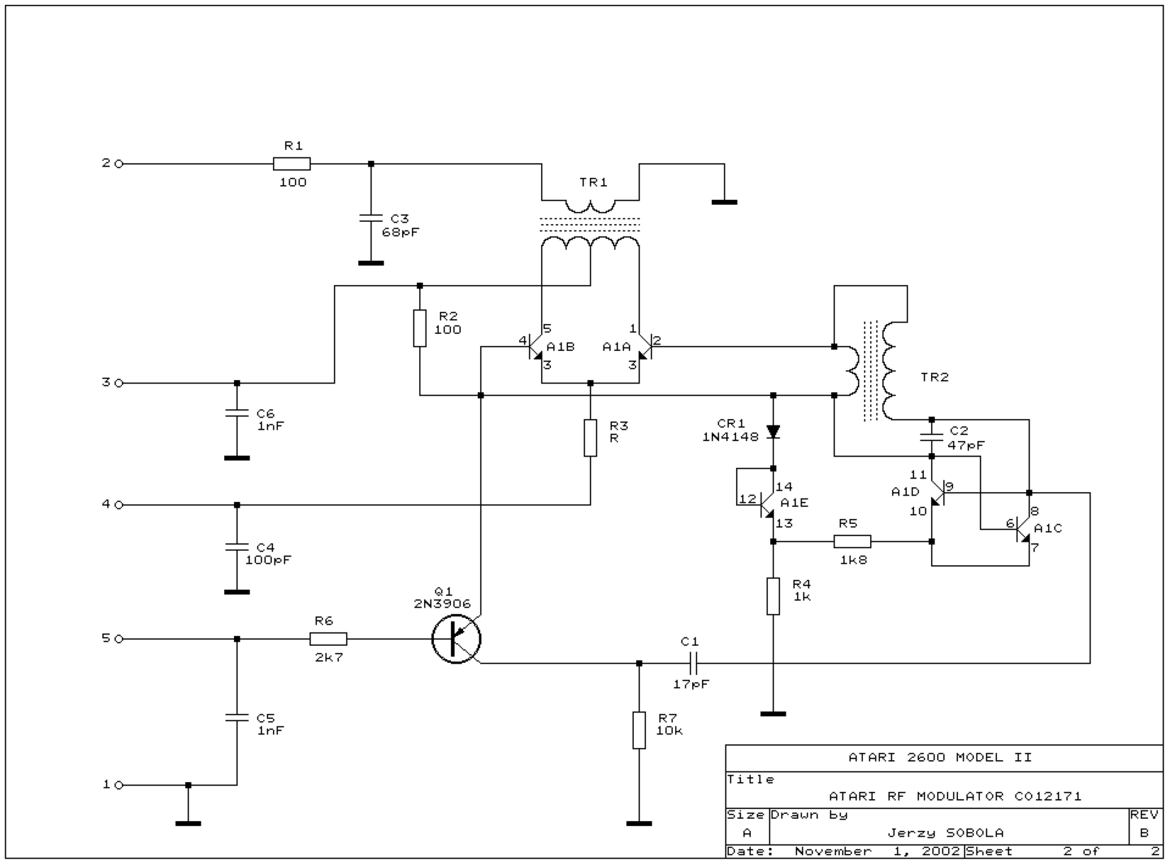
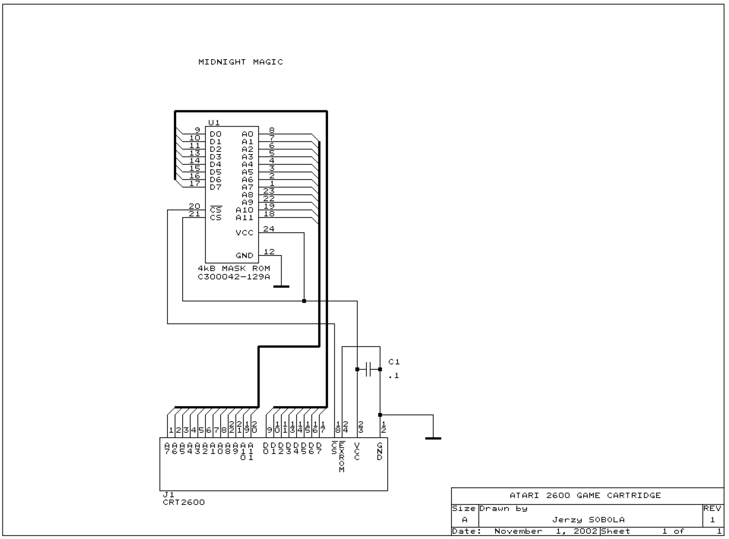
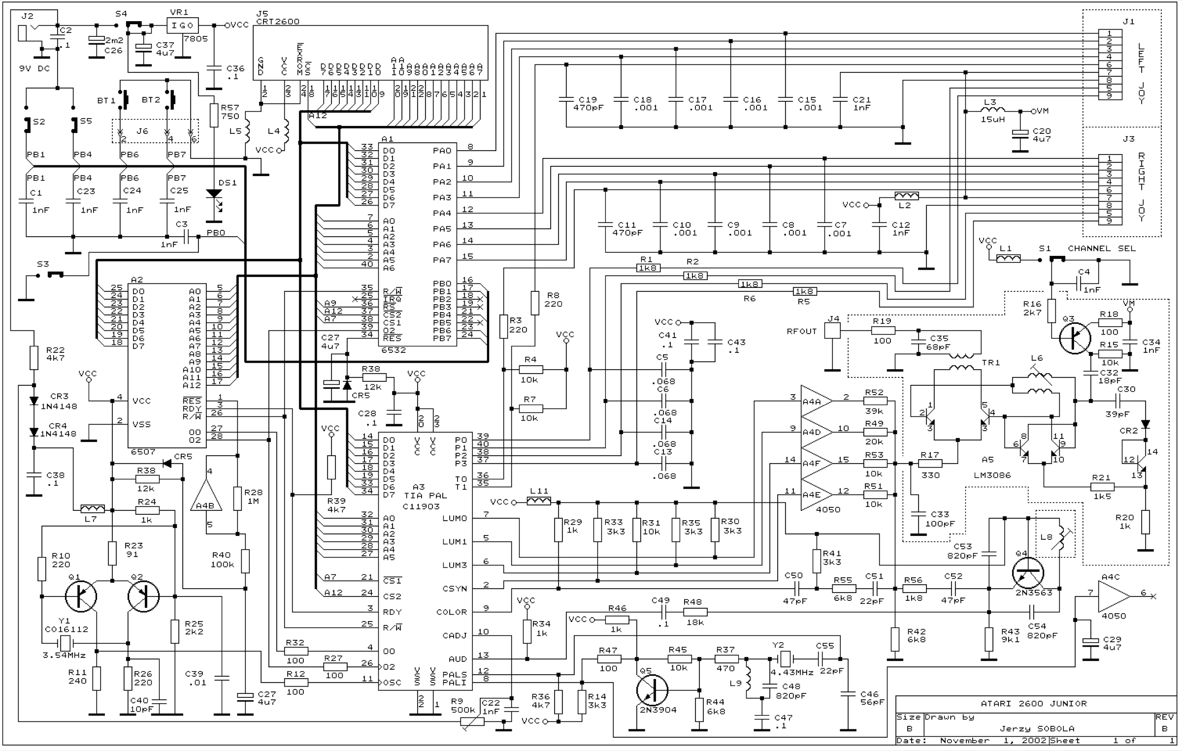
Sources & attribution
- Wikipedia — Atari 2600 — CC-BY-SA — https://en.wikipedia.org/wiki/Atari_2600
- TIA pinout (NTSC C010444 / PAL CO11903) — Console5 TechWiki — CC-BY-SA — https://wiki.console5.com/wiki/TIA
- Single-transistor composite mod (2N3904, 3.3 kΩ/2.2 kΩ, modulator pads) — mrpjevans, after Brighty83 (Retro.MMGN) — https://mrpjevans.com/composite-modding-the-atari-2600/
- Mods (buy/install) — Stone Age Gamer (Harmony Encore), RetroRGB (Atari), Tim Worthington / etim.net.au (2600RGB) — https://retrorgb.com/atari.html
Image:
-
atari-2600-board.jpg— Tetrodotoxine, CC BY-SA 4.0 — https://commons.wikimedia.org/wiki/File:Atari-2600-Four-Switch-Motherboard-Flat-1982.jpg

Review & corrections
How this space is used
Spotted a wrong value, an outdated procedure, a chip reference that does not match your board? Say so here, with what you observed (model, board revision, serial number, measurement). Every report is cross-checked against a source before anything changes — an unverifiable correction is published as “reported by …, not cross-checked” rather than silently applied.
Reading is open to everyone; posting requires signing in with Discord. Reports from the wiki's declared reviewers are handled first; anyone else's are read too, but go through a human before anything is changed.