Taito F3 System
Taito's high-end 2D base (1992), cartridge-based (like the Neo-Geo): 68020 + Ensoniq ES5505/5510, gorgeous sprites and effects. Darius Gaiden, Ray Force, Kaiser Knuckle, Puzzle Bobble 2/3/4, Elevator Action Returns… No suicide: swapping games is trivial.
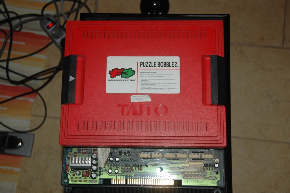
PCB Taito F3 (Puzzle Bobble 2) — photo by Cyberjobe, domaine public (Wikimedia Commons).
Identification
| Field | Value |
|---|---|
| Manufacturer | Taito |
| Year | 1992 |
| Type | 16/32-bit 2D, cartridge-based |
| Media | game cartridge (motherboard + cart) |
| Suicide? | no (no battery-backed encryption) |
Architecture
| Block | Chip | Role |
|---|---|---|
| CPU | Motorola 68EC020 | game logic |
| Sound CPU | Motorola 68000 | drives the sound |
| Sound | Ensoniq ES5505 (+ ES5510 ESP effects) | sample playback + reverb/effects |
| Video | Taito customs | multiple layers, zoomed sprites, line-scroll, alpha — Taito's "rich" 2D |
The F3 is Taito's 2D peak: fine-scrolling planes, tons of sprites, transparency
effects — hence the look of Darius Gaiden or Ray Force. Emulated in MAME
(taito/taito_f3.cpp).
Cartridge & conversion
The game is on a cartridge plugged into the F3 motherboard → trivial swap (like Neo-Geo/CPS-2, but no suicide). The lock is a dual region key (physical + region byte) → a bi-region conversion is possible. → Taito F3 converts (region, bi-region).
EPROM repair: 68020 program on 4 EPROMs (27C010/020/040 per game) → game-by-game EPROM table.
Notable games
Ray Force / Layer Section (Galactic Attack), Darius Gaiden (1994), Kaiser Knuckle, Grid Seeker, Bubble Bobble II / Bubble Symphony, Puzzle Bobble 2/3/4, Elevator Action Returns, Arkanoid Returns, Puchi Carat, Landmaker, Kirameki Star Road…
Common faults
| Symptom | Likely cause | Lead |
|---|---|---|
| Cartridge not read / crash | cartridge slot contacts | Clean edge + slot |
| Corrupt sprites/planes | Taito customs / RAM | RAM test, contacts |
| No/partial sound | ES5505/5510 | Sound-stage diagnosis |
| Wrong region | key / region byte | See converts (bi-region) |
| No image | Power, 68020, contacts | Base diagnosis |
Modernisation & mods
The common ground for every JAMMA board
Video, power, control panel and upscalers depend on the cabinet rather than the board: everything is centralised in Modernising a cabinet. To run the board outside a cabinet (at home, on a display): supergun.
- Battery 🟢: a save battery is fitted (settings/counters/RTC). ⚠️ On this platform, a dead battery does NOT kill the game — it is a leaking battery that corrodes traces. Check and replace it before it leaks → save batteries.
- Storage 🟢: a cartridge system — the modern route is a multi-game cart / flashcart rather than reprogramming, where one exists for the platform → PCB preservation hub.
- Scan rate 📺: ~15.44 kHz / 58.9 Hz — standard resolution, a classic 15 kHz chassis is fine — the most common JAMMA case → tri-sync and upscalers.
(Computed from the MAME sources —
taito/taito_f3.cpp— pixel clock ÷ htotal.) - FPGA / emulation: see the Emulation & FPGA section below.
Repair (technician)
- No suicide (no battery-backed encryption) — a dead board is a real fault.
- 68EC020 game + 68000 sound + Ensoniq ES5505 (+ ES5510 effects): silent sound / missing effects = the Ensoniq stage (ES5505/ES5510) + sample ROMs.
- Taito customs (line-scroll, alpha): corrupt planes/sprites = RAM + buffers first.
- Capacitors: recap sound + filtering. EPROM sockets: turned-pin socket.
→ Methods: PCB fault-finding · Recap · EPROM · Traces & vias
Expected clocks — measurement table ✅
Values extracted from the MAME sources for this platform. On a scope or frequency counter, a clock that is missing or off-value points straight at the crystal, the divider or the chip at fault — the fastest starting point on a dead board.
| Component | Expected clock | Role |
|---|---|---|
| M68EC020 | 16 MHz | main CPU |
How to read this table
Several values for one component = several board variants in this family (or several instances of the chip clocked differently). These frequencies are those of the clock signal at the component's input, not of its original crystal — on many boards the clock is divided down from a single master crystal.
Procedure — a dead board, step by step ✅
What this adds
The general method lives in PCB diagnosis. This is its application to this platform: the same order, but with the values actually expected here, so you do not have to go back and forth.
Tools: multimeter, oscilloscope (or frequency counter), current-limited bench supply, desoldering braid. → Tooling
If the board is still in a cabinet
A CRT holds its charge with the machine unplugged. → CRT safety
1. Inspection, power off. Corrosion, cut tracks, oxidised EPROM legs, leaking SMD capacitors, dubious earlier repairs.
2. The connector, before anything else. A large share of "dead boards" are a contact problem, not a fault. Clean the contacts with isopropyl alcohol and reseat — not with an abrasive eraser on a gold edge, which takes the plating off and brings the problem back worse. It costs two minutes and settles the question.
3. Power, measured on the board. Aim for +5.0 V measured as close as possible to where power reaches the board — not at the PSU output: the drop is in the loom, and that is exactly what makes a board boot on the bench and not in the cabinet. Where you probe depends on this board's connector — JAMMA edge, JVS loom or a proprietary harness — plenty of makers kept one long after JAMMA arrived — see Identification above. → Wiring Check −5 V and +12 V too if the sound stage uses them. Suspected short: bring it up current-limited and find the hot spot.
4. /RESET. It must release after power-up. Held low = the CPU never starts. A 1–2 Hz loop is not the reset circuit, it is the watchdog: the CPU is crashing at boot, so look at the bus, not at the reset.
5. Clocks — the values expected on this platform.
- M68EC020 → 16 MHz (Main CPU)
No clock on the M68EC020 (16 MHz) and there is no point measuring anything else: the fault is the crystal, the divider, or the chip itself. That single measurement splits a dead board in two.
6. Bus. Activity on the main CPU's address lines tells you whether it is running or frozen. Frozen with good clocks and good reset → work RAM, bus buffers, ROMs.
7. It boots but the picture or the sound is wrong — that is another job: see Common faults on this page, then signal tracing.
Emulation & FPGA
- Emulation: MAME (
taito/taito_f3.cpp). - FPGA / MiSTer: no confirmed dedicated core → MAME.
Lineage
After the B / F2 (wired) — the F3 moves to cartridge. Contemporary with the early 3D (Model 1, System 21).
Photos / assets
(To add: F3 motherboard, cartridge, ES5505.)
Sources & attribution
-
Photo PCB Taito F3 (Puzzle Bobble 2) — Cyberjobe, domaine public, Wikimedia Commons — https://commons.wikimedia.org/wiki/File:Puzzlebobble2pcb.JPG
-
MAME —
taito/taito_f3.cpp(68EC020, 68000, ES5505/5510, cartridge, games) — https://github.com/mamedev/mame - Internal page: Taito F3 converts
- Wikipedia — Taito F3 System — CC-BY-SA — https://en.wikipedia.org/wiki/Taito_F3_System

Review & corrections
How this space is used
Spotted a wrong value, an outdated procedure, a chip reference that does not match your board? Say so here, with what you observed (model, board revision, serial number, measurement). Every report is cross-checked against a source before anything changes — an unverifiable correction is published as “reported by …, not cross-checked” rather than silently applied.
Reading is open to everyone; posting requires signing in with Discord. Reports from the wiki's declared reviewers are handled first; anyone else's are read too, but go through a human before anything is changed.