GCE / MB Vectrex
A unique console (1982): it has its own vector screen (no TV needed). Black & white vector display with colour overlays. A cult object for collectors — but beware, it's a CRT (high voltage).
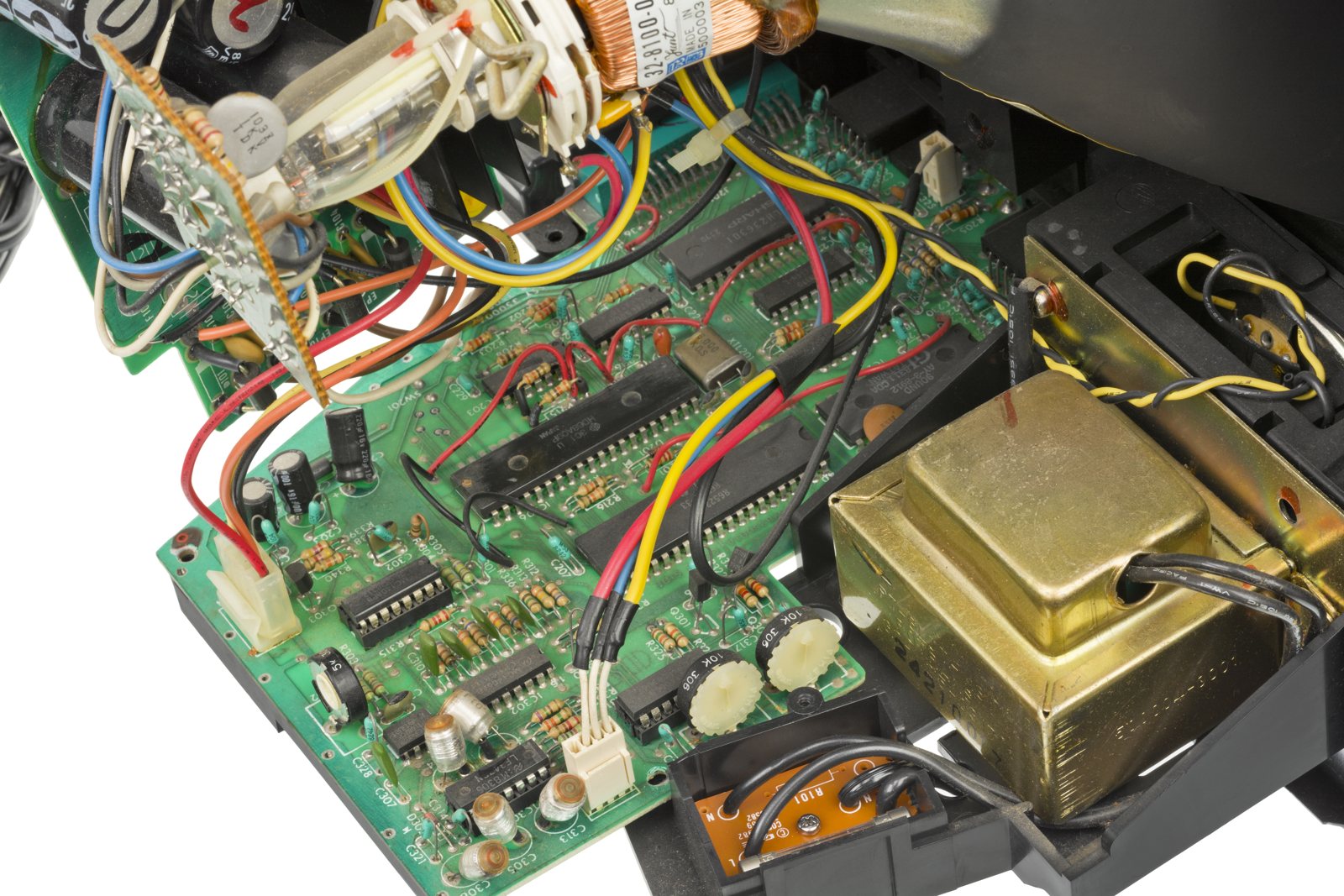
Identification
| Field | Value |
|---|---|
| Manufacturer | GCE / Milton Bradley |
| Release | 1982 |
| Display | Built-in B&W vector screen + overlays |
| Media | Cartridge |
Architecture (detail)
| Block | Chip | Clock | Role |
|---|---|---|---|
| CPU | Motorola 6809 | 1.5 MHz | |
| Display | DAC + analog integrators driving the CRT gun | vector drawing: no pixels, the beam traces lines (like Asteroids in the arcade) | |
| Sound | General Instrument AY-3-8912 (3-voice PSG) | + button handling | |
| Memory | 1 KB RAM | 8 KB ROM (BIOS/Mine Storm) |
The only consumer console with a vector screen: the image is monochrome, colour is simulated by plastic overlays placed on the screen. The CRT and its high voltage make some repairs dangerous (see below). The game Mine Storm is built into ROM (BIOS).
Accessories
- Light Pen: an optical pen (drawing, a few games).
- 3D Imager: spinning-disc glasses for a stereoscopic effect (rare, an ancestor of active 3D).
⚠️ High voltage (built-in CRT) & phosphor burn
It's a cathode-ray tube
The Vectrex contains a CRT with high voltage. Discharge before working on it; don't work alone if untrained. As on arcade vector cabinets, a stationary beam (a frozen vector) can burn the phosphor — cut power if a fixed, very bright dot appears.
Common faults
| Symptom | Likely cause | Lead |
|---|---|---|
| Shaky image / distorted vectors | Capacitors / adjustments | Recap; adjustments |
| Buzz / stray noise | Sound stage / caps | Targeted recap |
| No image (HV ok) | Vector stage / joints | Diagnosis + reflow |
| Cartridge not read | Contacts | Cleaning |
Original service manual ✅
Manufacturer manual archived locally. It typically carries the schematics, the block diagram, the expected voltages and waveforms, the parts list and the disassembly procedures — the reference when a symptom matches no known fault.
Status
A manufacturer document with no explicit licence, kept for preservation (machine long out of production) — the same position as for the cabinet and arcade manuals already archived here. Source: Internet Archive.
Procedure — a dead console, step by step ✅
There is a CRT in this machine
It holds its charge unplugged, and the high-voltage stage is right where your hands go. Discharge it before opening, and do not work on it alone. → CRT safety
What this adds
Ordered for a console, not for an arcade board: what kills these is almost never the CPU. It is, in real order, the power supply, the capacitors, the drive or the cartridge slot, and only then the logic. → PCB diagnosis
1. The power supply. Two cases, depending on the machine. External brick: ⚠️ read the marking on the machine, next to the socket, and check the adapter against it — voltage and polarity. A centre-negative machine fed centre-positive loses its fuse, sometimes its regulator; do not trust a third-party label or a generic tip. Internal supply (the machine plugs straight into the wall): mains is inside the shell. Unplug, wait, and confirm the large capacitors are discharged before touching the board. Either way, measure under load: a failing supply holds its voltage until it is asked for current.
2. The fuse. Many of these machines have one right behind the socket — it is the part designed to die. Test it in continuity, out of circuit. A fuse that blows again is a short, not a fuse problem.
3. Capacitors. On most machines of this age this is the default suspect rather than a last resort — leaking SMD electrolytics eat the tracks underneath before they give any other sign. ⚠️ Not all of them are like that: some carry very few and are not recapped on principle. Read what this page says about it before reaching for the iron. → Recap
4. The cartridge connector. Cartridge contacts with isopropyl alcohol, never an abrasive eraser: it takes the gold plating off and the problem comes back worse. On the machine side, inspect the slot pins — splayed, bent or oxidised — and check continuity between slot and board.
5. The display. There is no other TV to try — the tube is in the machine. No picture with sound is the high-voltage stage or the video amplifier, not the tube. And on a vector display a stationary beam burns the phosphor: if a bright fixed dot appears, switch off at once. See the dedicated section on this page.
6. Still nothing. Now, and only now, the logic: rails on the board, reset, clock, bus. → PCB diagnosis
Mods & repair — what to buy, how
Recap + CRT high voltage
The Vectrex is a vector CRT display: high voltage lingers even unplugged. Discharge the tube before any work → CRT safety. The recap is the #1 reliability topic (shrinking/shaking image, power).
- Flashcart: VecMulti (or VecFever) — SD multicart with the whole library + homebrew, plug-and-play 🟢. Clear overlays reissued by the community.
- Image adjustments 🟡: brightness / vector-linearity pots on the analog board (set them after the recap, tube cold then warm).
- Speaker buzz: documented filtering mods (the analog sound bleeds into the amp).
Photos / assets
(To add: Vectrex, vector screen, board, overlays.)
Advanced repair
⚠️ Integrated high-voltage CRT → CRT safety; recap (the No. 1 reliability issue). Methods: CRT safety · Recap · PCB fault-finding.
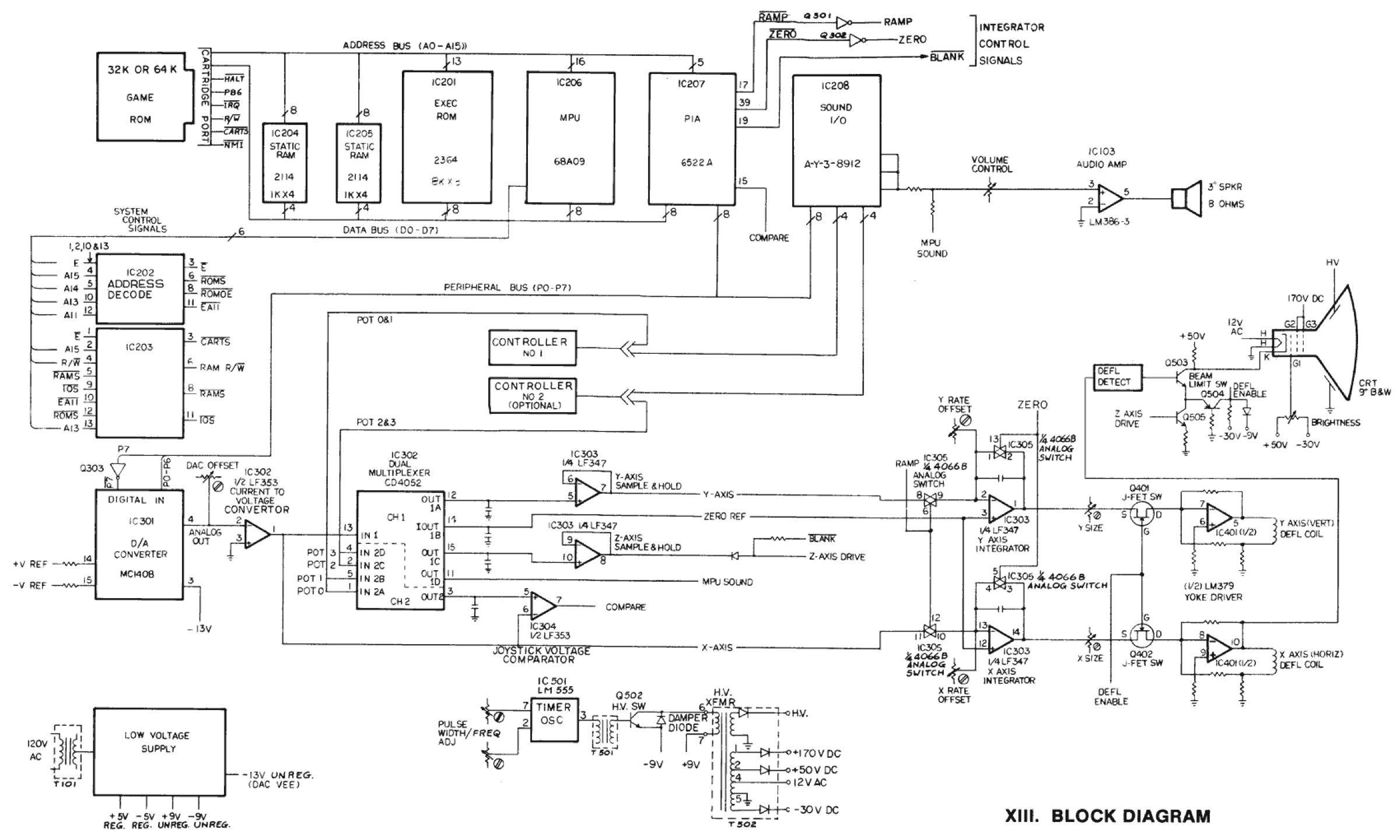
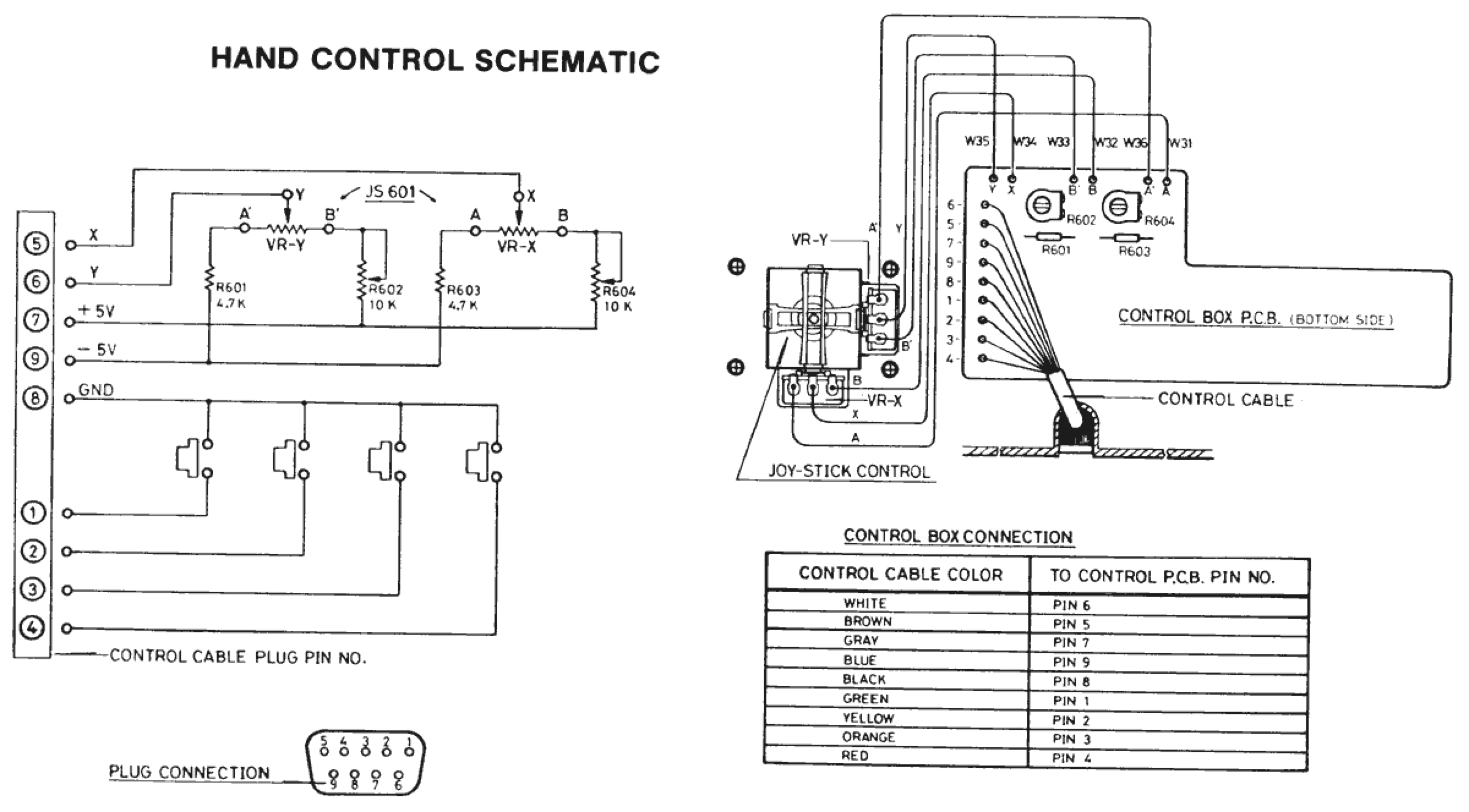
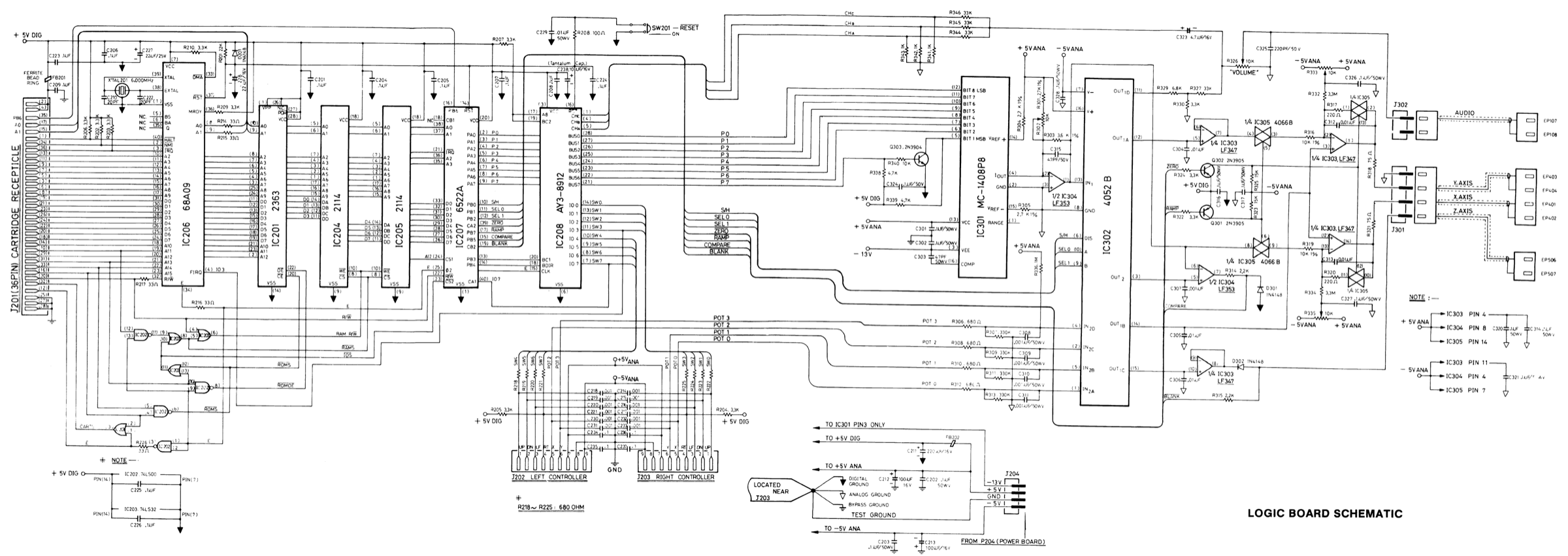
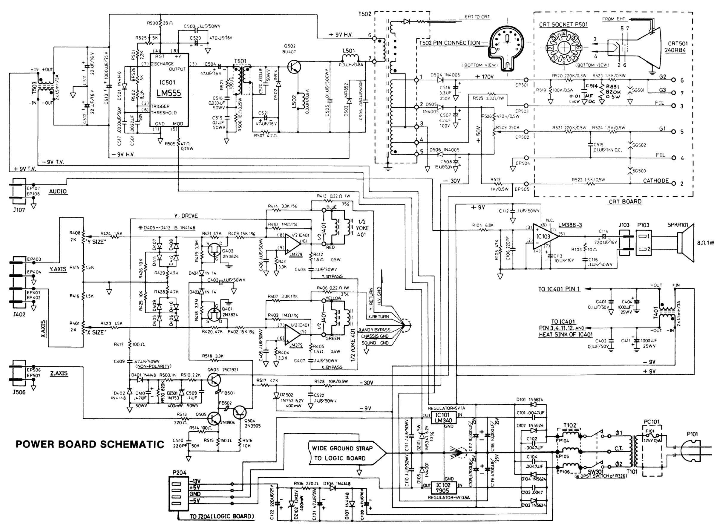
Vectrex schematics ✅
Block diagram, logic board, power board and hand controller. ⚠️ The power board and the tube circuit are extra-high-tension territory: see the safety box at the top of this page before touching them.
Provenance
Undocumented origin in the collection these schematics came from: no author and no licence is stated there.
Sources & attribution
ConsoleMods does NOT cover the Vectrex
Checked on 31/07/2026 via the ConsoleMods wiki search API: no page exists for the Vectrex. There is therefore no CC-BY-SA procedure to bring home for this machine — all the more so as, with its integrated vector CRT, it is a category of its own. This page's content rests on our existing sources, and nothing has been transposed from the wiki's other CRT consoles: high-voltage procedures do not generalise from one machine to another.
- Wikipedia — Vectrex — CC-BY-SA — https://en.wikipedia.org/wiki/Vectrex
Image:
-
vectrex-board.jpg— Evan-Amos, public domain — https://commons.wikimedia.org/wiki/File:GCE-Vectrex-Open-Motherboard.jpg

Review & corrections
How this space is used
Spotted a wrong value, an outdated procedure, a chip reference that does not match your board? Say so here, with what you observed (model, board revision, serial number, measurement). Every report is cross-checked against a source before anything changes — an unverifiable correction is published as “reported by …, not cross-checked” rather than silently applied.
Reading is open to everyone; posting requires signing in with Discord. Reports from the wiki's declared reviewers are handled first; anyone else's are read too, but go through a human before anything is changed.