IGS PGM (PolyGame Master)
IGS's cartridge-based arcade platform (1997): a motherboard + game cartridges. Famous for its IGS games (Knights of Valour, Oriental Legend…) and for hosting the 2002-2003 Cave shmups (DoDonPachi Dai-Ou-Jou, Ketsui, Espgaluda). Weak point: the ARM protection (IGS027A), whose internal ROM is the real lock.
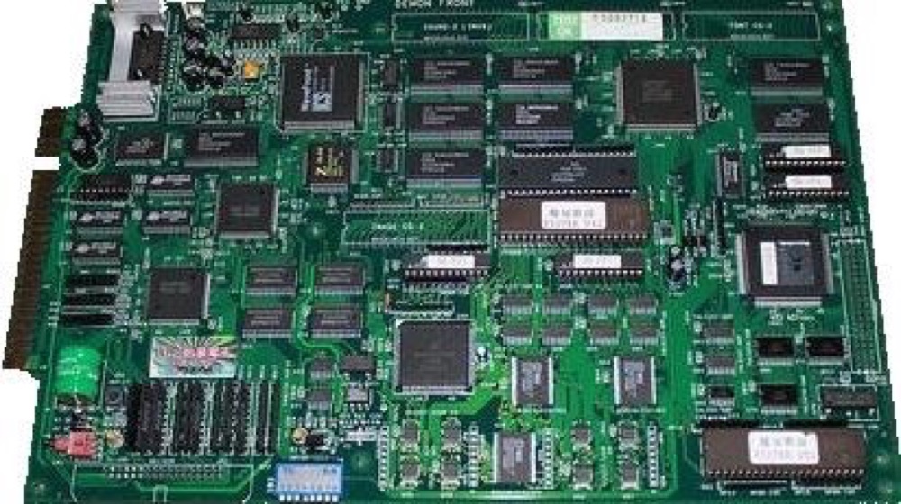
Cartouche PGM (Demon Front) — photo by Seero, CC BY-SA 1.0 (Wikimedia Commons).
Identification
| Field | Value |
|---|---|
| Manufacturer | IGS |
| Year | 1997 |
| Media | Cartridges (motherboard + game) |
| Connector type | JAMMA |
| Resolution | ~448×224 |
Architecture
| Block | Chip | Clock | Role |
|---|---|---|---|
| CPU | Motorola 68000 | 20 MHz | game logic |
| Sound | ICS2115 (WaveFront) | sample-based (wavetable) synthesis | |
| Video | IGS custom (IGS023) | zooming sprites + tilemaps | |
| Media | cartridges (PROG board + CHAR board) | common slot, you swap the game boards | |
| Protection | IGS025/022/028 ASIC (early games) → IGS027A (ARM7, late games) |
PGM (PolyGame Master, IGS, 1997): a Neo-Geo-style cartridge platform. The motherboard carries the 68000, the ICS2115, the IGS023 video chip and a BIOS; the game ships as cartridge(s) — typically a PROG board (program + sound + optional protection chip) and a CHAR/ROM board (graphics/sprites).
Protection & preservation
PGM has two generations of protection:
| Generation | Chip(s) | Examples | Lock |
|---|---|---|---|
| Early (1997-1998) | IGS025 ASIC + IGS022 / IGS012 / IGS028 | Dragon World II/3, Oriental Legend (Super), The Killing Blade | custom logic + protected data |
| Late (1999+) | IGS027A = ARM7 core with encrypted internal ROM | Knights of Valour (+ Plus), DoDonPachi Dai-Ou-Jou, Ketsui, Espgaluda, Oriental Legend 2, Demon Front, DoDonPachi II: Bee Storm | internal ROM of the ARM CPU (not directly readable) |
The real lock on late games is the IGS027A internal ROM: MAME explicitly notes "need internal ROM of IGS027A" for many titles. Those internal ROMs were extracted one by one over the years by the RE community, which is what enabled emulation. Some cartridges also carry a battery tied to the ASIC (region/state): a dead battery = degraded behaviour on those titles.
Notable games
- IGS: Knights of Valour / Sangoku Senki (+ Plus), Oriental Legend (+ Super), The Killing Blade, Dragon World II/3, Photo Y2K, Martial Masters, Demon Front, Dragon World 2001, DoDonPachi II: Bee Storm (an IGS game, non-Cave, on PGM).
- Cave (developed on PGM, 2002-2003): DoDonPachi Dai-Ou-Jou, Ketsui: Kizuna Jigoku Tachi, Espgaluda.
⚠️ Don't confuse them: DeathSmiles and DoDonPachi DaiFukkatsu are on Cave CV1000, not PGM. Cave moved from PGM to CV1000 in 2004.
Faults & preservation
| Symptom | Likely cause | Lead |
|---|---|---|
| Cartridge not read / corrupted graphics | Oxidised PROG/CHAR contacts | Clean the cartridge edges |
| ARM game won't boot | Flat ASIC battery / protection | Protection diag; re-key/multi solutions |
| No image | Motherboard (68000, IGS023), power | Base diagnosis |
| No sound | ICS2115 | Sound diagnosis |
- Targeted recap by age.
- Reference emulation: MAME (
igs/pgm.cpp). No FPGA/MiSTer core (68000 + IGS023 + IGS027A ARM protection).
→ PGM converts guide (IGS027A, de-protection, EPROM) · PGM multi
Modernisation & mods
The common ground for every JAMMA board
Video, power, control panel and upscalers depend on the cabinet rather than the board: everything is centralised in Modernising a cabinet. To run the board outside a cabinet (at home, on a display): supergun.
- Battery 🟢: a save battery is fitted (settings/counters/RTC). A leaking battery corrodes traces — check and replace it before it leaks → save batteries.
- Storage 🟢: a cartridge system — the modern route is a multi-game cart / flashcart rather than reprogramming, where one exists for the platform → PCB preservation hub.
- Scan rate 📺: ~15.62 kHz / 59.2 Hz — standard resolution, a classic 15 kHz chassis is fine — the most common JAMMA case → tri-sync and upscalers.
(Computed from the MAME sources —
igs/pgm.cpp— pixel clock ÷ htotal.) - FPGA / emulation: see the Emulation & FPGA section below.
Repair (technician)
- ARM protection (IGS027A) on the cartridge per game: an unreadable game = the cartridge ASIC, not the motherboard (community / MAME dumps).
- IGS023 custom (sprite zoom + tilemaps): corrupt = RAM + buffers first, the custom next (donor).
- Sound: ICS2115 (wavetable) — diagnose the sound stage.
- PROG / CHAR cartridges: oxidised contacts → clean. Capacitors: recap.
→ Methods: PCB fault-finding · Recap · EPROM · Traces & vias
Expected clocks — measurement table ✅
Values extracted from the MAME sources for this platform. On a scope or frequency counter, a clock that is missing or off-value points straight at the crystal, the divider or the chip at fault — the fastest starting point on a dead board.
| Component | Expected clock | Role |
|---|---|---|
| ICS2115 | 33.8688 MHz | WaveFront (sound) |
| M68000 | 20 MHz | main CPU |
| Z80 | 8.4672 MHz | sound CPU (usually) |
How to read this table
Several values for one component = several board variants in this family (or several instances of the chip clocked differently). These frequencies are those of the clock signal at the component's input, not of its original crystal — on many boards the clock is divided down from a single master crystal.
DIP settings ✅
1 games on this platform, settings extracted from the MAME sources (INPUT_PORTS_START blocks). The Position column gives the switch's physical reference on the board (SW2:!3,!4 = bank SW2, levers 3 and 4) — which is what lets you set it up without the paper manual. Games are sorted by MAME set name.
DIP settings — MAME set pgm
| Setting | Position | Options (default in bold) |
|---|---|---|
| Music | SW1:2 | Off · On |
| Voice | SW1:3 | Off · On |
| Free | SW1:4 | Off · On |
| Stop | SW1:5 | Off · On |
| Debug | SW1:8 | Off · On |
Check against your own board
These settings apply to the game and revision described by MAME. One title may have several DIP sets depending on region or revision, and some systems use soft-dips (settings in memory, via the test menu) rather than physical switches. In case of a discrepancy, the board's silkscreen and the test menu are authoritative.
See also: DIP reference · game manuals
Procedure — a dead board, step by step ✅
What this adds
The general method lives in PCB diagnosis. This is its application to this platform: the same order, but with the values actually expected here, so you do not have to go back and forth.
Tools: multimeter, oscilloscope (or frequency counter), current-limited bench supply, desoldering braid. → Tooling
If the board is still in a cabinet
A CRT holds its charge with the machine unplugged. → CRT safety
1. Inspection, power off. Corrosion, cut tracks, oxidised EPROM legs, leaking SMD capacitors, dubious earlier repairs.
2. The connector, before anything else. A large share of "dead boards" are a contact problem, not a fault. Clean the contacts with isopropyl alcohol and reseat — not with an abrasive eraser on a gold edge, which takes the plating off and brings the problem back worse. It costs two minutes and settles the question.
3. Power, measured on the board. Aim for +5.0 V measured as close as possible to where power reaches the board — not at the PSU output: the drop is in the loom, and that is exactly what makes a board boot on the bench and not in the cabinet. Where you probe depends on this board's connector — JAMMA edge, JVS loom or a proprietary harness — plenty of makers kept one long after JAMMA arrived — see Identification above. → Wiring Check −5 V and +12 V too if the sound stage uses them. Suspected short: bring it up current-limited and find the hot spot.
4. /RESET. It must release after power-up. Held low = the CPU never starts. A 1–2 Hz loop is not the reset circuit, it is the watchdog: the CPU is crashing at boot, so look at the bus, not at the reset.
5. Clocks — the values expected on this platform.
- ICS2115 → 33.8688 MHz (WaveFront (sound))
- M68000 → 20 MHz (Main CPU)
- Z80 → 8.4672 MHz (Sound CPU (usually))
No clock on the M68000 (20 MHz) and there is no point measuring anything else: the fault is the crystal, the divider, or the chip itself. That single measurement splits a dead board in two.
6. Bus. Activity on the main CPU's address lines tells you whether it is running or frozen. Frozen with good clocks and good reset → work RAM, bus buffers, ROMs.
7. It boots but the picture or the sound is wrong — that is another job: see Common faults on this page, then signal tracing.
Photos / assets
(To add: PGM motherboard, PROG cartridge, CHAR cartridge, IGS027A chip.)
The PGM test menu, read off the system manual ✅
The PGM System — User's Manual archived below is a platform manual, not a game one: it describes the test menu common to every PGM board. No text layer — read off the images.
Getting in: "PUSH [TEST] KEY TO ENTER THE MAIN MENU OF TEST", the TEST key being on pin 15, parts side, of the JAMMA edge.
The main menu — HARDWARE TEST · DIP. SW SETTING · OPERATOR SETTING · BOOK KEEPING ·
CALENDAR SETTING · SYSTEM RESET · EXIT. Navigate with the stick, confirm with button
A.
⚠️ CALENDAR SETTING is a menu in its own right: the PGM has a clock, and it is set
here.
The HARDWARE TEST submenu runs six tests: I/O TEST · SOUND TEST · R.G.B. TEST ·
SCREEN V.H. TEST · RAM TEST · COUNTER TEST.
⚠️ I/O TEST is left by pressing A and B simultaneously — the manual says so, and without
that you power-cycle the cabinet to get out. It shows all four players at once (1P, 2P, 3P, 4P),
each with its directions, buttons A B C D, START and COIN, plus the state of the eight DIP
switches in binary.
The manual's DIP table — 0/1 notation, not ON/OFF:
| Setting | Switch | Value shown |
|---|---|---|
| TEST MODE | 1 | 1 = YES |
| MUSIC | 2 | 0 = YES |
| VOICE | 3 | 0 = YES |
| FREE PLAY | 4 | 0 = NO |
| STOP MODE | 5 | 0 = NO |
The JAMMA pinout the manual gives — four buttons per player, marked A S1, B S2, C S3, D S4 on pins 22 to 25 on both sides:
| Pin | Parts side | Solder side |
|---|---|---|
| 1-2 | GND | GND |
| 3-4 | +5 V | +5 V |
| 6 | +12 V | +12 V |
| 8 | Coin meter 1P | Coin meter 2P |
| 10 | Speaker (+) | Speaker GND |
| 12-13 | Video red, blue | Video green, sync |
| 14 | — | SERVICE KEY |
| 15 | TEST KEY | — |
| 16-17 | Coin 1P, Start 1P | Coin 2P, Start 2P |
| 18-21 | Up, down, left, right (1P) | same (2P) |
| 22-25 | A S1, B S2, C S3, D S4 (1P) | same (2P) |
| 27-28 | GND | GND |
⚠️ The manual devotes a further page to 4 players' JAMMA I/O: players 3 and 4 do not go through this connector. See JAMMA wiring for the standard, and how this departs from it.
Archived original documents ✅
Manufacturer documents archived locally, found on Internet Archive on 13 August 2026 and identified from their title page. ⚠️ The items declare no licence — kept for preservation, provenance named.
- PDF — igs-pgm-system-user-manual.pdf — PGM SYSTEM — User's Manual, International Games System Co., Ltd, 14 pp. ⚠️ It covers the original PGM, not the PGM2 — the search had turned it up under "PGM2". Via Internet Archive
Sources & attribution
-
Photo Cartouche PGM (Demon Front) — Seero, CC BY-SA 1.0, Wikimedia Commons — https://commons.wikimedia.org/wiki/File:Demon_Front_PCB.png
-
MAME —
igs/pgm.cpp(68000 @ 20 MHz, ICS2115, IGS023, IGS025/022/028 ASIC → IGS027A ARM, "need internal ROM", IGS games + Cave DaiOuJou/Ketsui/Espgaluda, Bee Storm = IGS) — https://github.com/mamedev/mame/blob/master/src/mame/igs/pgm.cpp - Wikipedia — PolyGame Master — CC-BY-SA — https://en.wikipedia.org/wiki/PolyGame_Master
- System16 — IGS PGM Hardware — to reference

Review & corrections
How this space is used
Spotted a wrong value, an outdated procedure, a chip reference that does not match your board? Say so here, with what you observed (model, board revision, serial number, measurement). Every report is cross-checked against a source before anything changes — an unverifiable correction is published as “reported by …, not cross-checked” rather than silently applied.
Reading is open to everyone; posting requires signing in with Discord. Reports from the wiki's declared reviewers are handled first; anyone else's are read too, but go through a human before anything is changed.