Sega 32X¶
Sega's 32-bit add-on (1994) that plugs into the Mega Drive's cartridge port. Two SH-2, an extra VDP — but a notorious wiring setup (video pass-through + multiple power bricks) and a very short career. Super 32X (JP) / Mega 32X (EU) / Genesis 32X (US).
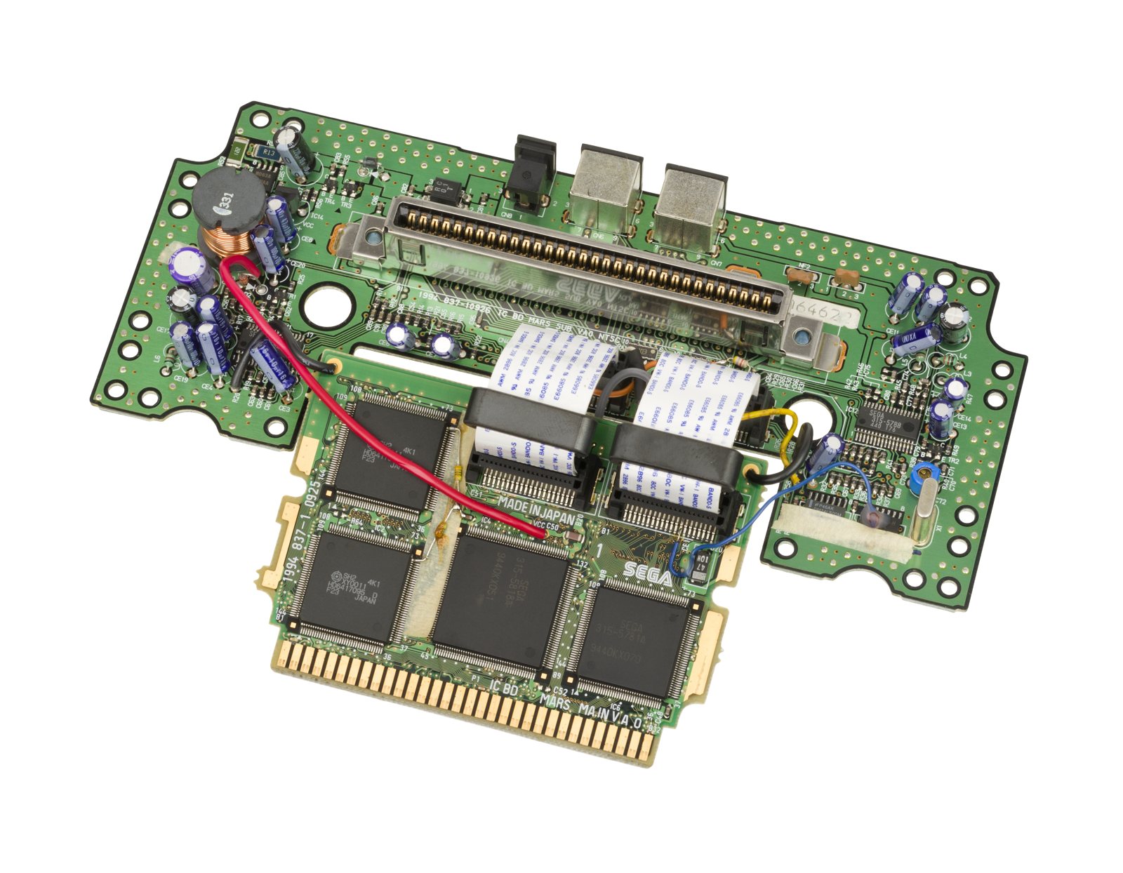
Identification¶
| Field | Value |
|---|---|
| Manufacturer | Sega |
| Release | 1994 |
| Type | Add-on (Mega Drive cartridge port) |
| Power | Own mains brick (+ the MD's) |
| Video | Video pass-through: the MD signal goes through the 32X |
Architecture (additions)¶
| Block | Chip | Clock | Role |
|---|---|---|---|
| CPU ×2 | Hitachi SH-2 | ~23 MHz | master/slave (compute, 3D) |
| Video | dedicated 32X VDP | framebuffer overlaid on the MD image (32,768 colours) via pass-through | |
| Sound | PWM (2 channels) | mixed with the MD sound | |
| RAM | 256 KB SDRAM + frame VRAM |
The 32X adds its SH-2 cores on top of the Mega Drive's 68000/Z80: both systems run in parallel and the final image is composed by overlay (hence the pass-through cable).
The wiring (the annoying part)¶
The 32X plugs into the cartridge port (with the game on top), has its own mains brick, and connects its A/V output to the MD's (pass-through cable). Hence the "cable nest" reputation (up to 3 bricks with a Mega-CD). A Mega-CD + 32X combo is possible (a few "Sega CD 32X" games).
Library: only ~40 games (Virtua Fighter, Star Wars Arcade, Knuckles' Chaotix, Doom, Kolibri…), the 32X having been dropped within months — hence its failure reputation. "Sega CD 32X" games (32X-enhanced FMV, e.g. Night Trap 32X, Corpse Killer) require MD + Mega-CD + 32X stacked.
Model compatibility
The 32X seats well on a Mega Drive/Genesis Model 1; on the smaller Model 2 it often needs a spacer for stability. It does not work with models lacking a true standard cartridge port (Nomad, Genesis 3 / CDX, clones). Also check 50/60 Hz compatibility: a 32X game follows the host MD's region.
⚠️ A/V wiring: the +5 V wire that destroys hardware ✅¶
A badly made link cable will fry the 32X, the Mega Drive, or both
The cable that connects TO the 32X must NOT have the +5 V pin wired. This applies to every 32X patch cable — except those with female inputs (which require a second patch cable).
The rule, put another way:
- A patch that does not connect to the 32X (the female Model 2 port kind) → wire all pins.
- Any patch cable that does connect to the 32X → never wire the +5 V pin.
(Source: ConsoleMods, CC-BY-SA.)
Why (technical insight from Ste, HDRetrovision)
Looking at the 32X schematics, Sega deliberately kept separate the Mega Drive +5 V (from the cartridge slot) and the +5 V generated internally by the 32X. The most noticeable reason appears to be power sequencing: the 32X +5 V cannot turn on unless the Mega Drive +5 V is present — which is exactly what you want.
On the 32X PCB, the A/V output port (to the TV) supplies its pin from the 32X's internal +5 V. You would think the A/V input port connects its +5 V pin to the Mega Drive cartridge +5 V — it does not: it also connects that pin to the 32X's +5 V.
Consequently, a patch cord carrying the Mega Drive +5 V will short to the 32X's +5 V rail, possibly causing power sequencing issues or back-feeding the 32X's voltage regulator from the opposite direction.
Why composite must be wired (genlock)
Composite video carries the colour subcarrier reference signal, and it must be provided over the AV Link cable for genlock between the Mega Drive and the 32X. Without it, the 32X free runs its encoder, which leads to phase misalignment and artefacts such as dot crawl. (Source: ConsoleMods, CC-BY-SA.)
Connectors: the 32X uses the same 9-pin mini-DIN as the Mega Drive Model 2, Genesis 3 and CDX. For RGB, therefore, use the same RGB cable as a Model 2.
- Model 2 / CDX: the standard male-to-male Model 2 patch cable (the one originally bundled).
- Model 1: the Model 1 does not use the same connector. Two routes —
- the most flexible: a Model 1 male → Model 2 female adapter left plugged into the Mega Drive permanently (it then behaves like a Model 2), plus the standard 32X patch cable. You keep a single RGB cable for both uses. Versions with a 3.5 mm audio lead additionally route stereo sound (useful with the front headphone output, or after the rear stereo mod).
- the most direct: a single Model 1 → 32X cable — but you then need a second RGB cable to play without the 32X.
- ⚠️ The adapter originally bundled with the 32X for the Model 1 only carries mono sound (the Model 1 A/V port had no stereo out).
- Worth knowing: Virtua Racing is not compatible with the 32X — one of the reasons not to leave the 32X plugged in permanently (along with the Power Base Converter).
32X revisions and Model 2 compatibility ✅¶
There are two 32X revisions, and the choice of host Mega Drive changes everything.
| Revision | Years | What you need to know |
|---|---|---|
| VA0 / MK-84000 | 1994-1995 | Problems on the Model 2 VA0: if nothing is plugged into the side expansion slot (the Sega CD one), many 32X games will refuse to work or lock up within minutes. |
| VA1 / MK-84000A | 1995-1996 | Sega added pull-down resistors on the data bits, fixing some of the Model 2 issues and eliminating the need for the Extension Unit. |
What the \"Extension Unit\" actually does (the mystery box)
The VA0 shipped with an Extension Unit. It acts as a terminator on the expansion port and contains pull-down resistors on the data bits — pins A4 through A11 and A13 through A20. So on a Model 2 VA0 with a VA0 32X: connecting a Sega CD or the Extension Unit resolves the problem. (Source: ConsoleMods, CC-BY-SA, in collaboration with io55.net.)
Model 2 VA2.3 and VA4: no known fix
Both 32X revisions have problems with Model 2 VA2.3 and VA4 Mega Drives, and there is currently no documented fix — the only known workaround is to load games from a flash cart instead of original cartridges. The Extension Unit does not fix this case.
Sega service bulletin fixes (Model 1) ✅¶
Soon after the 32X's release, Sega became aware of compatibility issues with certain Model 1 Mega Drive revisions and issued service bulletins to authorised service centres. All these fixes involve removing components from the Mega Drive motherboard and rerouting clock signals.
The symptom to recognise: as the Mega Drive warms up to room temperature, the EDCLK signal gradually becomes unstable — screen elements rendered by the 32X jitter (those rendered by the Mega Drive stay perfectly fine), then the 32X locks up. ⚠️ This can take up to an hour to manifest: hence the requirement for long testing.
Materials and tools: leaded solder, flux (optional but highly recommended), hookup wire, JIS/Phillips screwdriver, soldering iron, flush cutters, wire strippers, tweezers, desoldering braid (optional).
Disassembly common to both procedures¶
- Flip the Mega Drive over and remove the six case screws. Carefully pull off the top case and remove the connector on the power LED itself. You may need to straighten the LED leads with needlenose pliers (they are typically bent over). ⚠️ Do not remove the power LED on the motherboard end: its connector is soldered directly to the board.
- Remove the screws for the top RF shield and set it aside. Then the screw underneath the
headphone jack PCB, the two long screws on each side of the cartridge port, and the
three long screws on the heat sink.
- Asian (and Japanese) Mega Drives have no RF shielding, but still have several screws securing the board to the bottom case.
- ⚠️ Do not mix up these screws: using a long screw in the wrong place will damage the bottom case.
- Pull the power jack PCB out of its screw boss, then carefully lift the motherboard out of the bottom case.
Procedure — VA4 Mega Drive (Asian and PAL)¶
Two signals are at fault: EDCLK (external dot clock) and VCLK (68000 clock), whose stock quality is not "clean" enough for the 32X.
- Board upside down: locate C112, a disc-type ceramic capacitor soldered between one of the pads for C19 and the board. Desolder it and KEEP IT — this is the 33 pF that will be reused in step 5.
- Locate C78 and C100, and desolder both:
- C78 = a 1206 SMD capacitor around the centre of the board;
- C100 = another disc-type capacitor below the cartridge port.
- Tip for C78: load both its pads with solder and heat both points at the same time to "sweep" it off the board. Be careful not to bridge the pads.
-
Solder a wire between the topmost pad of C10 and ground. Ground can be found in many places, but Sega recommended the middle pad of EM16, one of the line filters for controller port 1.
Source ambiguity — check the photo before soldering
The source does write "C10" at this step (and in its figure 2 caption), immediately after having you remove C100. Both references exist on the board, and we transcribe "C10" as written without deciding for the source: check figure 2 on the ConsoleMods page (linked in sources) before soldering.
-
Board right side up: locate FB7, a ferrite bead located directly above the master clock oscillator. Remove it (cut it out or desolder it), then jump the two points with a small piece of wire or a component lead.
- Locate C92, another disc ceramic capacitor, near the left side of IC4 — the 315-5364 bus arbiter. Desolder it and solder the 33 pF saved in step 1 in its place. You may need a small length of wire to connect one of the 33 pF leads to one of the pads.
- Reassemble for testing with a 32X. ⚠️ Test for at least an hour to make sure the 32X will not lock up once the Mega Drive is fully warmed up. Only once stability is confirmed should you fully reassemble.
Procedure — VA5 / VA6 / VA6.5 / VA6.8 Mega Drive (all regions)¶
Here only VCLK is at fault. The fix is far shorter.
- Same disassembly (see above).
- Locate C78 (1206 SMD) and remove it by loading both pads with solder then carefully "sweeping" it off the board.
- Solder a wire from the topmost pad of C78 to pin 15 of the 68000 — the very large
chip located directly next to the cartridge port. Pin 15 is the clock input.
- ⚠️ Route the wire AROUND the cartridge port pins, never through them: the cartridge port support in the bottom shell would crush the wire.
- Reassemble and test for at least an hour, as above.
This fix is not PAL-only
The VA5/6/6.5/6.8 fix applies to all regions, not just PAL consoles. Only the two VA4 fixes are specific to Asian and PAL Mega Drives.
32X 50/60 Hz region mod ✅¶
The 32X is technically region free — but it has its own video output
32X games actually use the host console to determine what region they are running on: the 32X itself is region free. Most 32X games are only region locked between NTSC and PAL, and make no US vs Japanese distinction like most region-locked Mega Drive games do — Japanese and US 32X units are in fact completely identical aside from slight cosmetic differences.
However: since the 32X has its own video output, it must also conform to the video frequency of its region (50 Hz for PAL, 60 Hz for US and Japan), which leads to issues when an NTSC 32X is used on a 50 Hz console and vice versa. Region-modding the host console is therefore not enough: the 32X must be switched too.
The exact point: the frequency is determined by pin 32 of the 315-5788 video encoder/mixer chip — held high (5 V) = 60 Hz, held low (ground) = 50 Hz.
| 32X region | Zero-ohm jumper populated on | Ties pin 32 to | Result |
|---|---|---|---|
| NTSC (US / Japan) | R42 | 5 V | 60 Hz |
| PAL | R43 | ground | 50 Hz |
The mod is therefore simply a matter of removing that jumper and connecting a switch in its place.
Materials: leaded solder, flux, desoldering braid, an SPDT switch (slide or toggle, down to preference), hookup wire, preferably 28 AWG, isopropyl alcohol or flux remover. Tools: JIS/Phillips screwdriver, soldering iron, flush cutters, wire stripper, cordless drill with a step bit, file set (if using a slide switch).
- Flip the 32X over, remove the four case screws and the top case.
- Remove the RF shielding screws. Removing the motherboard is highly recommended but not totally necessary.
- Locate the 315-5788, on the right-hand side of the board. Directly above its upper
left corner are the two sets of pads R42 and R43.
- US or Japanese 32X → R42 is populated. PAL 32X → R43 is.
- Apply flux to the jumper, load up the iron tip with solder, heat both sides at once and carefully sweep the jumper off onto the tip.
- Clean the pads with desoldering braid, then clean the area with IPA / flux remover.
- Tin the pads for both R42 AND R43.
- Tin the three points of the switch, then solder three wires to them.
- Decide where the 50/60 Hz switch goes — preferably at the rear of the top case, largely out of sight, and clear of the RF shielding and top case screw bosses.
- Drill and mount the switch (for a slide switch: drill small, then file the hole so the switch throws freely).
- Cut the wires to length: no tension, and easy to reopen the case later.
- Braid the wires together if they are not already bundled.
- Solder the middle pin wire to either lower pad of R42 or R43. The outer pins go to the top pad of R42 and the top pad of R43 (order down to preference). Route the wires clear of the shielding and screw bosses.
- Test on a display accepting both 50 and 60 Hz, or any upscaler (RetroTINK, OSSC). If both video modes are recognised, reassemble.
Coil whine (noisy inductor) — 3 fixes ✅¶
The 32X creates its 5 V rail with a buck converter topology based on the MC34064 (or similar) DC-DC converter IC: a far more efficient way to take the 32X's 10 V input down to 5 V, at greater than 80 % efficiency. But many 32X units suffer from a noisy coil — likely caused by the converter going into discontinuous conduction mode, making the inductor vibrate at an audible frequency.
| Fix | Complexity | Result |
|---|---|---|
| Buzzkill — complete replacement power circuit | medium | Removes the original inductor and disables the original power circuit; completely eliminates the possibility of a ringing inductor |
| Modifying the existing regulator (frequency + feed-forward) | least | Noise eliminated in most gameplay situations, but persists at light load (playing a Mega Drive game, idling in an EverDrive menu) |
| New NCP3063 / NCV3063 converter | slightly more complex | The best: no audible noise in any load condition |
Simple route — timing / feed-forward fix¶
Replace C85 with a 1 nF (1000 pF) C0G/NP0 capacitor, then connect the positive side of C85 / IC pin 3 to the input voltage on R50 via an 86.6 kΩ leaded resistor.
This supplies external charge current to the timing capacitor C85, thereby reducing the duty cycle of the converter and causing the oscillator to run at a higher frequency. The design frequency selected here is 100 kHz (component tolerances will shift it slightly).
Recommended route — NCP3063 / NCV3063 converter¶
The NCP(V)3063 was designed as an updated replacement for the MC34064: it adds internal thermal shutoff and a much higher switching frequency capability (up to 300 kHz). The circuit — designed by zaxour — targets 200 kHz and is mostly drop-in, the only additional component being the feed-forward resistor. No whine was observed in any load condition, after more than 24 hours of testing.
| Qty | Component | Replaces |
|---|---|---|
| 1 | NCP3063 or NCV3063, SOIC-8 | IC13 |
| 1 | 0.1 Ω resistor, size 2512, 2 W or greater | R50 |
| 1 | 4.3 nF ceramic, size 0603, C0G/NP0, rated 25 V or greater | C85 |
| 1 | 11.8 kΩ leaded resistor, 1/8 W or greater | (added: feed-forward) |
| 1 | 100 µH leaded inductor, DC rated 2 A or greater | L7 |
Implementation: remove IC13, C85, R50 and L7, fit the replacements, then solder the 11.8 kΩ resistor from IC13 pin 3 to R50 — preferably the side closer to the DC power jack.
Restoring Master System support with the 32X fitted¶
The 32X prevents Master System games (via the Power Base Converter) from working. A circuit by DogP (Sega-16 forums) restores it.
Principle: let A21-A23 act normally in Mega Drive and 32X mode, but drive A21-A23 in SMS mode. The circuit controls the direction using the /M3 signal (pin B30), passing the 32X signals when it is high.
Limited compatibility — know this first
This mod's compatibility is limited to Model 2 systems, and was found to be inconsistent across multiple boards of the same revision in DogP's original thread. Model 1 systems do not work with this mod. It is speculated that the main 32X gate array and address selector (315-5818 and 315-5805) are much less lenient on bus timings, resulting in the inconsistency. Work RAM and VRAM are also suspected. (Source: ConsoleMods, CC-BY-SA.)
Materials: a 74ACT241 chip, Kapton or masking tape, double-sided tape.
- Put a piece of Kapton or masking tape across the pins so that only a small bit is exposed, to prevent solder from travelling down the pin. Solder a wire to A21, A22 and A23.
- Cut the three traces connected to the cart socket — or alternatively put Kapton over pins 8/9/10 of the ribbon cable.
- Attach the 74ACT241 securely with double-sided tape (for example under a ribbon cable).
- Solder wires to the 32X A21-A23 output (CN1 pins B11-B13) and to +5 V / GND (left side of the capacitor is +5 V, right side is GND).
- Route the wires to avoid getting in the way of reassembly, solder to the chip, reassemble and test.
Master System games incompatible with this mod (original list: MicroNut99)
These titles do not work with the mod:
Addams Family (Europe) · Aladdin (Europe) · American Pro Football (Europe) · Battle Out Run (Europe) · Cosmic Spacehead (Europe) · Desert Strike (Europe) · Dinobasher Starring Bignose the Caveman (Europe, proto) · Earthworm Jim (Brazil) · Fantasy Zone II - The Tears of Opa-Opa (Japan and USA/Europe) · Fire & Forget II (Europe) · Gauntlet (Europe) · James Bond 007 - The Duel (Brazil and Europe) · Jurassic Park (Europe) · Kenseiden (Japan and USA/Europe) · Line of Fire (Europe) · Loretta no Shouzou (Japan) · The Lucky Dime Caper Starring Donald Duck (Europe, and beta) · Masters of Combat (Europe) · Micro Machines (Europe) · Out Run (USA/Europe) · Out Run 3-D (Europe) · Pit Fighter (Brazil and Europe) · Populous (Europe) · Road Rash (Europe) · RoboCop 3 (Europe) · RoboCop versus The Terminator (Europe) · Scramble Spirits (Europe) · The Simpsons - Bart vs. The World (Europe) · Sonic The Hedgehog (USA/Europe) · Sonic's Edusoft (proto) · Summer Games (Europe, and beta) · Super Smash T.V. (Europe) · Super Space Invaders (Europe) · Super Tennis (USA/Europe) · Super Wonder Boy - Monster World (Japan) · Taz-Mania (Europe, beta) · Tecmo World Cup '92 (Europe, beta) · Tecmo World Cup '93 (Europe) · Teddy Boy Blues (Japan, proto Ep-MyCard) · The Terminator (Brazil and Europe) · Thunder Blade (Japan) · World Grand Prix (Europe and USA) · WWF Wrestlemania - Steel Cage Challenge (Europe) · Zaxxon 3-D (World, and beta) · Zillion (Japan/Europe) · Zool - Ninja of the 'Nth' Dimension (Japan/Europe).
Common faults¶
| Symptom | Likely cause | Lead |
|---|---|---|
| Unstable image / colours | Contacts 32X↔MD, pass-through | Clean contacts, check the A/V cable |
| No 32X display | Bad connection / power | Check its own power + wiring |
| Corrosion / degraded sound | SMD capacitors | Recap |
| Unstable game | Cartridge port contacts | Reseat, cleaning |
| 32X image jitters then locks up after ~1 h warming up | EDCLK/VCLK not clean enough on a Model 1 MD (VA4 / VA5-6.8) | Sega service bulletin fixes |
| Games refuse to work or lock up within minutes (Model 2 VA0) | Side expansion slot not terminated with a VA0 32X | Connect a Sega CD or the Extension Unit → Revisions |
| Instability on Model 2 VA2.3 / VA4 | Known incompatibility, no documented fix | Workaround: play from a flash cart |
| Permanent high-pitched whine | Buck converter inductor (discontinuous conduction) | 3 coil whine fixes |
| Dot crawl / crawling colours | Composite missing from the link cable → no genlock | Full cable (minus +5 V) → A/V wiring |
| 32X and/or MD damaged after a home-made cable | +5 V pin wired on the cable going to the 32X | ⚠️ See the danger box in A/V wiring |
Original service manual ✅¶
Manufacturer manual archived locally. It typically carries the schematics, the block diagram, the expected voltages and waveforms, the parts list and the disassembly procedures — the reference when a symptom matches no known fault.
- 32X — Sega service manual (1995) — PDF
- 32X — PDF — the manual also covers use with the Sega CD / Mega-CD
Status
A manufacturer document with no explicit licence, kept for preservation (machine long out of production). Source: Internet Archive.
Procedure — a dead console, step by step ✅¶
This machine does not run on its own
It needs a Mega Drive. Before opening anything, prove the host is good with a plain cartridge — otherwise you spend the day inside the add-on for a fault that is not in it. → Mega Drive
What this adds
Ordered for a console, not for an arcade board: what kills these is almost never the CPU. It is, in real order, the power supply, the capacitors, the drive or the cartridge slot, and only then the logic. → PCB diagnosis
1. The power supply. Two cases, depending on the machine. External brick: ⚠️ read the marking on the machine, next to the socket, and check the adapter against it — voltage and polarity. A centre-negative machine fed centre-positive loses its fuse, sometimes its regulator; do not trust a third-party label or a generic tip. Internal supply (the machine plugs straight into the wall): mains is inside the shell. Unplug, wait, and confirm the large capacitors are discharged before touching the board. Either way, measure under load: a failing supply holds its voltage until it is asked for current.
2. The fuse. Many of these machines have one right behind the socket — it is the part designed to die. Test it in continuity, out of circuit. A fuse that blows again is a short, not a fuse problem.
3. Capacitors. On most machines of this age this is the default suspect rather than a last resort — leaking SMD electrolytics eat the tracks underneath before they give any other sign. ⚠️ Not all of them are like that: some carry very few and are not recapped on principle. Read what this page says about it before reaching for the iron. → Recap
4. The cartridge connector. Cartridge contacts with isopropyl alcohol, never an abrasive eraser: it takes the gold plating off and the problem comes back worse. On the machine side, inspect the slot pins — splayed, bent or oxidised — and check continuity between slot and board.
5. Video output. Isolate the machine from the display: another cable, another TV, another input. A sizeable share of "dead consoles" are a dead cable, or a display that will not lock onto what this machine outputs — see the video section of this page for what that is.
6. Still nothing. Now, and only now, the logic: rails on the board, reset, clock, bus. → PCB diagnosis
Mods & preservation — what to buy, how¶
- Shim/spacer adapter: seats the 32X in the cartridge port for a reliable contact — bad seating is the #1 cause of crashes/black screen. 3D-print (community STLs) or buy one.
- RGB link cable: the 32X overlays its video onto the MD's through a short external cord (MD → 32X → TV). Keep it clean/un-oxidised — it's a common source of interference. For clean RGB, combine 32X + a Triple Bypass on the host MD. → see Mega Drive.
- Preventive recap: aging power/video electrolytics (community cap kit by reference).
- Region: follows the host MD.
- See Mega Drive § Add-ons.
Photos / assets¶
(To add: 32X on the MD, internal board, wiring.)
Advanced repair
MD ↔ 32X connector contacts = the No. 1 cause of crashes / no picture; then recap. Methods: PCB fault-finding · Recap · Traces & vias.
Sources & attribution¶
- Wikipedia — Sega 32X — CC-BY-SA — https://en.wikipedia.org/wiki/32X
- ConsoleMods Wiki — 32X Service Bulletin Fixes — CC-BY-SA — official Sega EDCLK/VCLK fixes, VA4 and VA5/6/6.5/6.8 procedures, detailed disassembly, one-hour warm test — https://consolemods.org/wiki/Genesis:32X_Service_Bulletin_Fixes
- ConsoleMods Wiki — 32X Model Differences — CC-BY-SA — VA0/MK-84000 vs VA1/MK-84000A, the Extension Unit as a terminator (pull-downs A4-A11 and A13-A20), the VA2.3/VA4 case with no fix — in collaboration with io55.net — https://consolemods.org/wiki/Genesis:32X_Model_Differences
- ConsoleMods Wiki — 32X Video Output — CC-BY-SA — ⚠️ never wire +5 V, power sequencing explained by Ste (HDRetrovision), genlock via the composite subcarrier, Model 1 / Model 2 cabling — https://consolemods.org/wiki/Genesis:32X_Video_Output
- ConsoleMods Wiki — 32X Region Mod — CC-BY-SA — pin 32 of the 315-5788, R42 (5 V/60 Hz) and R43 (ground/50 Hz) jumpers, SPDT switch procedure — https://consolemods.org/wiki/Genesis:32X_Region_Mod
- ConsoleMods Wiki — 32X Noisy Inductor Fix — CC-BY-SA — cause (MC34064 buck in discontinuous conduction), Buzzkill, C85/R50 86.6 kΩ mod, NCP3063/NCV3063 conversion by zaxour with BOM — https://consolemods.org/wiki/Genesis:32X_Noisy_Inductor_Fix
- ConsoleMods Wiki — 32X Restore SMS Support — CC-BY-SA — DogP's 74ACT241 circuit (Sega-16), A21-A23 driven via /M3 pin B30, Model 2 limits, incompatibility list by MicroNut99 — https://consolemods.org/wiki/Genesis:32X_Restore_SMS_Support
An honesty note on a source ambiguity
In the VA4 procedure, the ConsoleMods source writes "C10" at the ground-wire step, immediately after having you remove C100. Both references exist on the board and we did not decide on the source's behalf: the reference is transcribed as written, with an explicit pointer to figure 2 on the source page for verification before soldering. No silent correction was made.
Image:
-
32x-board.jpg— Evan-Amos, public domain — https://commons.wikimedia.org/wiki/File:Sega-Genesis-32X-Motherboard-Top.jpg

Review & corrections
How this space is used
Spotted a wrong value, an outdated procedure, a chip reference that does not match your board? Say so here, with what you observed (model, board revision, serial number, measurement). Every report is cross-checked against a source before anything changes — an unverifiable correction is published as “reported by …, not cross-checked” rather than silently applied.
Reading is open to everyone; posting requires signing in with Discord. Reports from the wiki's declared reviewers are handled first; anyone else's are read too, but go through a human before anything is changed.