Nintendo 64
Nintendo's 64-bit console (1996), cartridge-based, with the MIPS VR4300 CPU and the RCP coprocessor (SGI). Preservation points: no native RGB (a board-revision- dependent mod), the modern HDMI mods, and analog stick wear (THE controller repair).
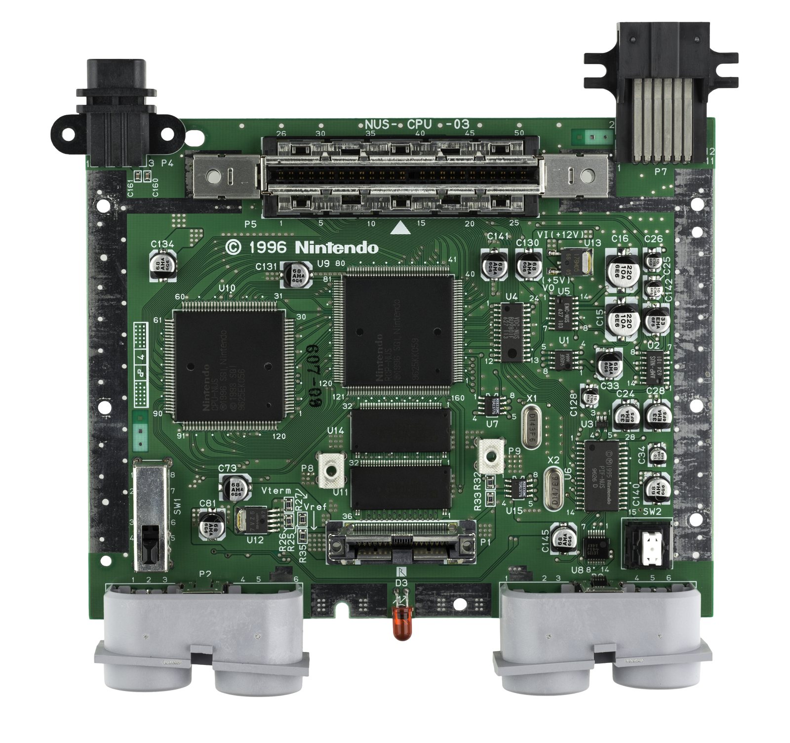
Identification
| Field | Value |
|---|---|
| Manufacturer | Nintendo |
| Release | 1996 (JP/US), 1997 (EU) |
| Generation | 5th (64-bit) |
| Native video output | Composite / S-Video — RGB not native |
| Region / lockout | CIC (cartridge notch) + NTSC/PAL |
| Media format | Cartridge (SRAM/EEPROM/flash save) |
Architecture (detail)
| Block | Chip | Clock | Role |
|---|---|---|---|
| CPU | NEC VR4300 (MIPS R4300i, 64-bit) | 93.75 MHz | Main core |
| Coprocessor | RCP (Reality Coprocessor, SGI) | 62.5 MHz | RSP (geometry + audio) + RDP (rasterisation) |
| RAM | 9-bit Rambus RDRAM | ~500 MB/s | 4 MB → 8 MB with the Expansion Pak |
| Cartridge | PRG + save | — | SRAM / EEPROM 4k-16k / FlashRAM (battery on some) |
- Resolutions: 320×240 native; 640×480 possible (often with an Expansion Pak). Anti-aliasing and the blur are characteristic of the RDP.
- The RDRAM has high latency — a notorious bottleneck.
- Programmable RSP microcode: the RSP runs a microcode (Fast3D, F3DEX…) that studios could rewrite. Factor 5 (Indiana Jones, Rogue Squadron) wrote its own microcode to push the hardware — hence big visual gaps between games on the same console. Long a headache for emulation (each custom microcode to handle).
- 4 built-in controller ports: 4-player multiplayer without a multitap (a strong N64 selling point, e.g. GoldenEye, Mario Kart 64).
Expansion Pak & Jumper Pak
The N64 boots with 4 MB of RDRAM; a top slot takes a RAM module:
- Jumper Pak: a terminator (no extra RAM) shipped by default. It must be present if you have no Expansion Pak — otherwise the console won't start.
- Expansion Pak: raises the RAM to 8 MB. Required by some games (Donkey Kong 64, The Legend of Zelda: Majora's Mask) or to unlock modes (Perfect Dark single-player, high resolutions). You remove the Jumper Pak to install it.
Saves (per game)
The save depends on the cartridge, not the console:
| Type | Detail | Lost when battery dies? |
|---|---|---|
| SRAM (battery-backed) | battery in the cartridge | Yes → replace the cartridge battery |
| EEPROM 4k / 16k | non-volatile memory | No |
| FlashRAM | flash memory (late games) | No |
| Controller Pak | memory card in the controller (CR2032 battery) | Yes (for the card) |
Controller & accessories (expansion slot)
The N64 controller has an expansion slot on the back that takes:
- Rumble Pak: one of the first mainstream force-feedback devices (Star Fox 64) — powered by 2 AAA batteries.
- Controller Pak: a memory card (CR2032 battery) for some games' saves.
- Transfer Pak: a bridge to Game Boy / GBC cartridges (Pokémon Stadium reads your Pokémon GB save).
One accessory at a time: you swap Rumble ↔ Controller ↔ Transfer Pak.
N64DD (disk add-on, Japan)
The 64DD is a magnetic disk drive that attaches under the N64 (Japan only, via the Randnet service). A commercial failure, very few titles (Mario Artist, F-Zero X Expansion Kit…). A collector's item; a rare piece.
Video outputs & RGB
- Composite / S-Video stock (the RCP outputs YCbCr converted by a video DAC — no direct RGB).
- RGB not native, and depends on the board revision:
- NUS-CPU-01 to -03: compatible video DAC → simpler "passive" RGB mod.
- NUS-CPU-04 and up: modified DAC → needs an active board (N64RGB / Tim Worthington) or a digital mod.
- Digital HDMI: UltraHDMI, PixelFX (N64 Digital / Retro GEM) — tap the RCP's digital bus directly (perfect image).
Common faults
| Symptom | Likely cause | Lead |
|---|---|---|
| Loose / imprecise stick (controller) | Analog stick wear | Replace with a new stick (GameCube-type kit) |
| Dull RF/composite image | Non-RGB output | RGB or HDMI mod |
| Cartridge not read / crash | Cartridge contacts | Cleaning |
| Yellowed plastic | UV | Retrobright |
Step-by-step disassembly procedures ✅
6 procedures transcribed from the iFixit guides, with difficulty and estimated time.
| Procedure | Difficulty | Time |
|---|---|---|
| Disassembling Nintendo 64 Cartridge | Easy | 5 minutes |
| Cleaning the cartridge slot | Very easy | 5 minutes |
| Repairing Nintendo 64 Bottom Cover | Moderate | 15 to 20 minutes |
| Repairing Nintendo 64 Metal Plate | Easy | 15 minutes |
| Repairing Nintendo 64 Motherboard | Easy | 15 to 20 minutes |
| Repairing Nintendo 64 Top Cover | Easy | 5-10 minutes |
Disassembling Nintendo 64 Cartridge
When games have been in storage or used for years on end, they need to get a good dose of TLC. In extreme cases you need to crack them open to get everything. It can be tense opening up a loved game in the fear that you'll destroy it. Alternatively, you can open up a game no one liked and make it into an innocuous enclosure for something else.
- First flip your game over and you'll see two screws using the 3.8mm "Gamebit" screwdriver bit. A 3.0U Spanner bit can also get them out.
- Take the screws out and peel the case off starting from the top taking care not to force it due to the tabs at the bottom of the cartridge. Outlined in Red
- The two halves of the case should come apart easily.
- On the inside of the front plastic casing the game board and metal shielding are attached with two Phillips head screws. Unscrew them to remove the shielding and access the game board.
- The top of the metal shielding held on with pressure tabs. Be sure to press down firmly when reassembling.
- With the shielding off, the main circuit board and pins can be seen.
- The only thing holding in the board is the plastic shield on the bottom of the cartridge. No screws are holding it in and is easily removed.
- Now you can fully take out the cartridge board from the casing.
- Here you can fully clean the pin set and inspect for damage to the circuit board.
- NOTE: The top edges of the board are made asymmetrically so it can only go into the casing one way. Near the Blue Circles
- The only thing holding in the board is the plastic shield on the bottom of the cartridge. No screws are holding it in and is easily removed.
- Now you can fully take out the cartridge board from the casing.
- Here you can fully clean the pin set and inspect for damage to the circuit board.
- NOTE: The top edges of the board are made asymmetrically so it can only go into the casing one way. Near the Blue Circles
Cleaning the cartridge slot
Cleaning the cartridge slot will fix most of the problems with the Nintendo 64.
- Open the slot with your finger. Blow along the length of the cartridge slot with the air duster.
Repairing Nintendo 64 Bottom Cover
This is how you remove the bottom cover
- Remove everything from the bottom cover.
Repairing Nintendo 64 Metal Plate
This guide shows how to remove the metal plate that covers the motherboard.
- Remove the 14 screws shown using the large Phillips screwdriver.
- Remove the metal plate by sliding it back then up.
- Remove the 2 screws shown using the small Phillips screwdriver.
- Remove the screw to the right of the LED using the large Phillips screwdriver.
- Remove the small metal bracket from the back of the expansion pack slot.
- Remove the small metal bracket from the front of the expansion pack slot with the metal spudger.
- Remove the small metal bracket using the spudger.
- Remove the 7 screws shown using the large Phillips screwdriver.
Repairing Nintendo 64 Motherboard
This guide will show how to replace the Nintendo 64 motherboard.
- Remove the 4 screws shown using the large Phillips screwdriver.
Repairing Nintendo 64 Top Cover
This guide will assist in removing the top cover of the Nintendo 64.
- Remove the expansion pack cover.
- Remove the expansion pack using the metal spudger.
- This can also be accomplished using a small spoon.
- Remove the 6 screws shown with a gamebit head or screwdriver.
- Remove the 2 front legs.
Source, licence and scope
iFixit guides, under Creative Commons BY-NC-SA — attribution, non-commercial, share-alike. Only the text is reproduced; the step photos stay on iFixit. ⚠️ These guides target the model named in the title: on another revision, the screws and the order of removal may differ.
Procedure — a dead console, step by step ✅
What this adds
Ordered for a console, not for an arcade board: what kills these is almost never the CPU. It is, in real order, the power supply, the capacitors, the drive or the cartridge slot, and only then the logic. → PCB diagnosis
1. The power supply. Two cases, depending on the machine. External brick: ⚠️ read the marking on the machine, next to the socket, and check the adapter against it — voltage and polarity. A centre-negative machine fed centre-positive loses its fuse, sometimes its regulator; do not trust a third-party label or a generic tip. Internal supply (the machine plugs straight into the wall): mains is inside the shell. Unplug, wait, and confirm the large capacitors are discharged before touching the board. Either way, measure under load: a failing supply holds its voltage until it is asked for current.
2. The fuse. Many of these machines have one right behind the socket — it is the part designed to die. Test it in continuity, out of circuit. A fuse that blows again is a short, not a fuse problem.
3. Capacitors. On most machines of this age this is the default suspect rather than a last resort — leaking SMD electrolytics eat the tracks underneath before they give any other sign. ⚠️ Not all of them are like that: some carry very few and are not recapped on principle. Read what this page says about it before reaching for the iron. → Recap
4. The cartridge connector. Cartridge contacts with isopropyl alcohol, never an abrasive eraser: it takes the gold plating off and the problem comes back worse. On the machine side, inspect the slot pins — splayed, bent or oxidised — and check continuity between slot and board.
5. Video output. Isolate the machine from the display: another cable, another TV, another input. A sizeable share of "dead consoles" are a dead cable, or a display that will not lock onto what this machine outputs — see the video section of this page for what that is.
6. Still nothing. Now, and only now, the logic: rails on the board, reset, clock, bus. → PCB diagnosis
Capacitor list (NTSC motherboard, per CXX reference) ✅
Source: Console5 TechWiki. 18 caps (revisions and PAL differ slightly; the power supply has its own list per model):
| Ref | µF | V |
|---|---|---|
| C15, C16 | 220 | 10 |
| C24, C28, C142 | 33 | 25 |
| C25, C26, C34, C128 | 10 | 16 |
| C33, C73, C81, C130, C131, C134, C140, C141, C145 | 68 | 10 |
Power block: per-reference list varies by PSU model (110 V / 220 V) — see Console5. To transcribe per reference if needed.
Popular mods — what to buy, where, procedures
Access / tooling
Opening: 4.5 mm gamebit (console) + 3.8 mm / tri-wing (Y) (controller) screwdrivers. Temp- controlled iron, flux. Procedures from ConsoleMods (CC-BY-SA). Soldering: 🟢 none · 🟡 · 🟠 · 🔴.
Video — the N64 is (almost) never RGB stock
-
Analog RGB: two cases depending on your board's video DAC —
-
"RGB-compatible" N64 (VDC-NUS / VDC-NUS A DAC, NTSC): RGB already exists internally, you just amplify it (simple mod, exact procedure below).
-
Modified DAC (NUS-CPU-04+ / PAL Funtastic): no usable analog RGB → an active N64RGB board (Tim Worthington / borti4938) or a digital mod. → N64 RGB page.
- Digital HDMI (perfect image): N64Digital (PixelFX), UltraHDMI (Retroactive, discontinued), Retro GEM, PicoDVI-N64 (DVI), HISPEEDIDO N64HDMI (budget). → N64 digital page.
-
DIY RGB amp mod (VDC-NUS N64) — exact points (transcribed from ConsoleMods, CC-BY-SA)
Check first: with the shielding off (4.5 mm tool), find a chip labelled VDC-NUS or VDC-NUS A. Present → compatible. Absent → active/digital board needed.
BOM: THS7316 video amp (or THS7314, identical install) on a small board, 3× 75 Ω resistors (lowest tolerance), 26-30 AWG wire, flux.
- On the solder side of the motherboard, find the RGB vias labelled R8, R9, R10. Flux each, solder a wire in each:
| Signal | Via |
|---|---|
| Red | R8 |
| Green | R9 |
| Blue | R10 |
⚠️ Keep the stripped wire very short: if it protrudes on the other side it touches the VDC-NUS chip and can short pins. (Alternative if the vias won't take: solder directly to the VDC-NUS — pin 17 = Red, 19 = Green, 21 = Blue.)
- Those 3 wires → amp inputs (THS7316 + 75 Ω per channel).
- Amp outputs → multi-out: R, G, B + +5 V + ground "G" (bottom of the board).
-
Sync: simplest = an RGB cable that gets sync from luma; otherwise direct CSYNC (see the N64 video cables).
-
Test: Super Mario 64 (clear R/G/B at the title screen). Re-plug the memory module (no boot without it) and don't run it long without the heat sink.
N64 blur (deblur) — transcribed from ConsoleMods (CC-BY-SA)
Two distinct blurs:
-
Horizontal 320→640 interpolation (smoothing): cannot be disabled in hardware/software. The UltraHDMI / N64Digital / N64RGB kits have a "deblur" feature that adjusts horizontal sampling to compensate; a well-tuned OSSC gets close.
-
RCP effects (anti-aliasing, dither): driven by the VI_CONTROL_REG register (address 0x04400000) — value set by the game, changeable via GameShark codes or a ROM patch (playable on EverDrive/emulator). Useful bits (e.g. Mario Kart 64): bit 8-9 = anti-aliasing, bit 16 = dither filter, bit 3 = gamma boost, bit 4 = DIVOT. Disabling AA + dither = a much sharper image.
Controller — the worn stick (THE N64 issue)
- The stock analog stick (geared potentiometer) wears out (mushy, imprecise). Fix: replace the module — SteelSticks64 kits, Hall-effect or GameCube-style modules, far more durable. Cleaning/regreasing only delays the wear.
Region / de-zoning
- The N64 region lock is mostly physical: the plastic slot tabs (different NTSC/PAL) block the other-region cartridge. Fix 🟡: remove/trim those tabs, or fit a Universal Cartridge Tray (a 3D-printed repro) — no electronics.
- ⚠️ Nuances: a PAL console stays at 50 Hz (slower game); NTSC-U/NTSC-J cross fine once the tabs are removed, but PAL↔NTSC also differs in video timing and a few games region-check at boot (matched CIC) → the physical trim covers most cases, not a universal guarantee. (No open-licensed CIC pinout → not detailed here.)
Play your library — flashcart
- EverDrive-64 X7 / X5 (Krikzz) — a microSD cartridge, plug-and-play 🟢; the X7 adds USB, RAM save, RTC. Where: Krikzz, Stone Age Gamer, RetroTowers…
Misc (dedicated ConsoleMods guides)
- Controller Pak FRAM Mod: battery-free saves (FRAM). Overclock Mod, Digital Audio (SPDIF), Rumble Pak Power Mod, Expansion Pak 4→8 MB (required by some games).
Preservation & homebrew
- Flashcart: EverDrive-64 (Krikzz), 64drive — library + homebrew on SD, handling save types and the CIC.
- Emulation: long difficult (RDP/microcodes); now mature (Mupen64Plus/RMG, Ares, accurate ParaLLEl-RDP, the N64Recomp static-recompilation project).
Photos / assets
(To add: NUS-CPU board, RCP, A/V output, controller stick.)
Advanced repair
Cartridge contacts (blowing ≠ cleaning: use IPA) + few electrolytics; a save battery in some cartridges. Methods: PCB fault-finding · Backup batteries · Recap.
Archived manufacturer documentation ✅
Manufacturer documentation archived locally. ⚠️ These are owner's and reference manuals, not service manuals: they give the specifications, the connectors and the expected behaviour, but not the schematics or troubleshooting voltages.
Status
Manufacturer documents with no explicit licence, kept for preservation (machines out of production for decades).
Sources & attribution
- Wikipedia — Nintendo 64 — CC-BY-SA — https://en.wikipedia.org/wiki/Nintendo_64
- Console5 TechWiki — N64 (board/PSU per-reference recap BOM) — https://wiki.console5.com/wiki/Nintendo_64
- ConsoleMods — N64: RGB Mod DIY RGB Amp (VDC-NUS DAC required, vias R8/R9/R10 = R/G/B or VDC-NUS pins 17/19/21, THS7316 amp + 3× 75 Ω, multi-out output +5V/G) — CC-BY-SA — https://consolemods.org/wiki/N64:RGB_Mod_DIY_RGB_Amp
- ConsoleMods — N64 (deblur VI_CONTROL_REG, HDMI, stick) — CC-BY-SA — https://consolemods.org/wiki/N64:N64_Mods_Wiki
Image:
-
n64-board.jpg— Evan-Amos, public domain — https://commons.wikimedia.org/wiki/File:Nintendo-N64-Motherboard-Top.jpg

Review & corrections
How this space is used
Spotted a wrong value, an outdated procedure, a chip reference that does not match your board? Say so here, with what you observed (model, board revision, serial number, measurement). Every report is cross-checked against a source before anything changes — an unverifiable correction is published as “reported by …, not cross-checked” rather than silently applied.
Reading is open to everyone; posting requires signing in with Discord. Reports from the wiki's declared reviewers are handled first; anyone else's are read too, but go through a human before anything is changed.