Bally / Midway Astrocade
Gorf, Wizard of Wor, Seawolf II, Space Zap. The American base of the early eighties, absent from this wiki until now. Everything on it derives from the NTSC colour crystal, and the game changes the speech synthesiser's own clock to alter the voice.
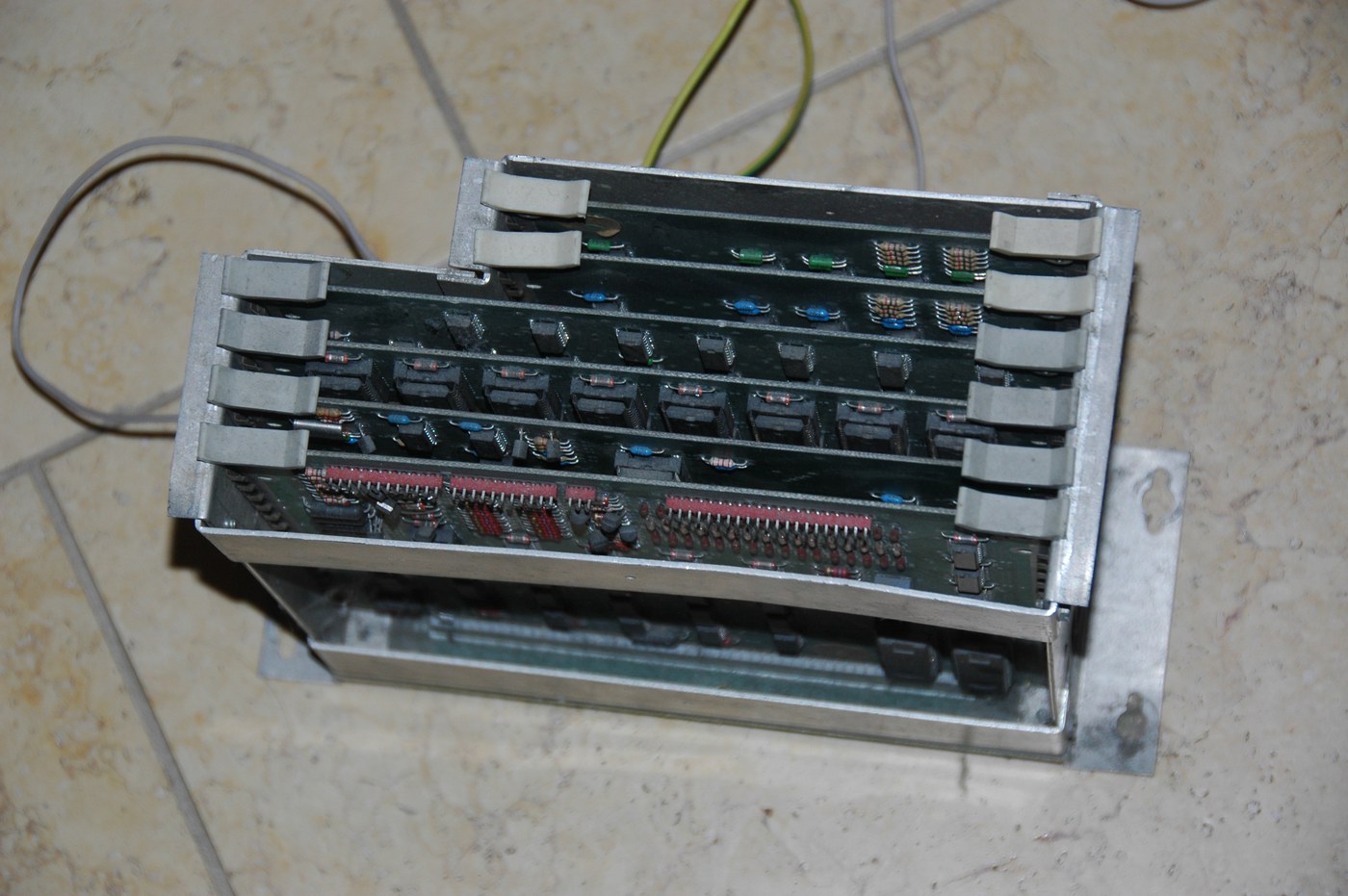
Identification
| Field | Value |
|---|---|
| Manufacturer | Bally / Midway (USA) |
| Years | 1978-1983 |
| Master crystal | 14.31818 MHz — the NTSC colour crystal |
| System clock | 7.159090 MHz (14.31818 ÷ 2) |
| CPU | Z80 @ ~1.7898 MHz (system clock ÷ 4) |
| Sound | ASTROCADE I/O custom @ ~1.7898 MHz — one or two, game depending |
| Speech | Votrax SC01 — ⚠️ see below |
| Scan rate | ~15.73 kHz / ~60.0 Hz — 455 × 262, 352 × 240 visible |
| PCB format | proprietary |
One crystal, from CPU to picture
The 14.31818 MHz is television's NTSC colour crystal. Divided by 2 it gives the system clock, by 8 the Z80, and it clocks the display directly — hence a scan rate exactly at the NTSC standard.
The consequence: a general clock failure has one possible cause, and the picture cannot drift independently of the processor.
Expected clocks — measurement table ✅
| Component | Expected clock | Role |
|---|---|---|
| Z80 | ~1.7898 MHz | Main CPU |
| ASTROCADE I/O | ~1.7898 MHz | sound — one or two of them |
| Votrax SC01 | 756 kHz · 782 kHz | speech synthesis — ⚠️ variable |
⚠️ The Votrax changes clock mid-game
This is the detail that confuses a frequency counter.
756 kHz or 782 kHz, at the software's choice
The Votrax SC01 does not run at a fixed frequency: the game switches its clock between 756 kHz and 782 kHz in software, to change the voice's inflection.
Measuring either is therefore normal, and a value that changes while you measure indicates no fault at all. That is how Gorf and Wizard of Wor pitch their voices.
Notable games
Seawolf II · Space Zap · Wizard of Wor (1980) · Gorf (1981) · The Adventures of Robby Roto (1981) · Extra Bases · Professor Pac-Man (1983) · Demons & Dragons (1982).
Common faults
| Symptom | Probable cause | Next step |
|---|---|---|
| Nothing starts, no clocks at all | 14.31818 MHz crystal | Everything derives from it: one possible cause |
| No speech | Votrax SC01 or its driver | ⚠️ its clock varies normally — see the box |
| Partial sound | one of the two ASTROCADE I/O chips | Some games have two |
| No picture | system clock or the video stage | The picture is clocked by the master crystal |
| Out-of-standard picture | impossible if the crystal is good | The scan rate is locked to NTSC |
Repair (technician)
- Start with the master crystal. On this platform a general clock failure has one explanation.
- Do not conclude anything about the Votrax from a single measurement: its clock is switched by the game.
- Check how many ASTROCADE I/O chips are fitted before diagnosing partial sound.
- Common period parts: the Z80 and the Votrax SC01 can still be found; the ASTROCADE customs cannot.
→ Methods: PCB diagnosis · Recap
Procedure — a dead board, step by step ✅
What this adds
The general method lives in PCB diagnosis. This is its application to this platform: the same order, but with the values actually expected here, so you do not have to go back and forth.
Tools: multimeter, oscilloscope (or frequency counter), current-limited bench supply, desoldering braid. → Tooling
If the board is still in a cabinet
A CRT holds its charge with the machine unplugged. → CRT safety
1. Inspection, power off. Corrosion, cut tracks, oxidised EPROM legs, leaking SMD capacitors, dubious earlier repairs.
2. The connector, before anything else. A large share of "dead boards" are a contact problem, not a fault. Clean the contacts with isopropyl alcohol and reseat — not with an abrasive eraser on a gold edge, which takes the plating off and brings the problem back worse. It costs two minutes and settles the question.
3. Power, measured on the board. Aim for +5.0 V measured as close as possible to where power reaches the board — not at the PSU output: the drop is in the loom, and that is exactly what makes a board boot on the bench and not in the cabinet. Where you probe depends on this board's connector — JAMMA edge, JVS loom or a proprietary harness — plenty of makers kept one long after JAMMA arrived — see Identification above. → Wiring Check −5 V and +12 V too if the sound stage uses them. Suspected short: bring it up current-limited and find the hot spot.
4. /RESET. It must release after power-up. Held low = the CPU never starts. A 1–2 Hz loop is not the reset circuit, it is the watchdog: the CPU is crashing at boot, so look at the bus, not at the reset.
5. Clocks — the values expected on this platform.
- Z80 → ~1,7898 MHz (Main CPU)
- ASTROCADE I/O → ~1,7898 MHz (son — un ou deux exemplaires)
- Votrax SC01 → 756 kHz · 782 kHz (synthèse vocale — ⚠️ variable)
No clock on the Z80 (~1,7898 MHz) and there is no point measuring anything else: the fault is the crystal, the divider, or the chip itself. That single measurement splits a dead board in two.
Several values for one component means several board variants in this family, not several readings on the same one: identify yours before calling a clock wrong. That is the mistake that replaces a healthy crystal.
6. Bus. Activity on the main CPU's address lines tells you whether it is running or frozen. Frozen with good clocks and good reset → work RAM, bus buffers, ROMs.
7. It boots but the picture or the sound is wrong — that is another job: see Common faults on this page, then signal tracing.
Modernisation & mods
- No suicide: no battery-backed protection.
- Scan rate 📺: ~15.73 kHz / 60 Hz, NTSC standard — ordinary 15 kHz chassis.
- ⚠️ Do not host ROMs — method only.
Emulation & FPGA
MAME covers the family (bally/astrocde.cpp, driver by Nicola Salmoria, Mike
Coates, Frank Palazzolo and Aaron Giles), speech synthesis included.
Photos / assets
(To take: the 14.31818 MHz crystal, the Votrax SC01 — an uncommon chip —, and a board with two ASTROCADE I/O chips if you meet one.)
Archived manufacturer documentation ✅
Manufacturer documentation archived locally. ⚠️ These are owner's and reference manuals, not service manuals: they give the specifications, the connectors and the expected behaviour, but not the schematics or troubleshooting voltages.
Status
Manufacturer documents with no explicit licence, kept for preservation (machines out of production for decades).
Sources & attribution
Text (synthesised here; sources listed for attribution):
- MAME —
src/mame/bally/astrocde.cpp(BSD-3-Clause / GPL, driver by Nicola Salmoria, Mike Coates, Frank Palazzolo and Aaron Giles):ASTROCADE_CLOCKdefined as 14.318181 MHz ÷ 2, the Z80 and ASTROCADE I/O at that clock ÷ 4, one or two sound generators depending on the game, 455 × 262 (352 × 240 visible) timing clocked directly by the system clock; and the Votrax SC01 whose clock is switched in software between 756,000 and 782,000 Hz with an inflection control — https://github.com/mamedev/mame/blob/master/src/mame/bally/astrocde.cpp
Image:
-
gorf-rack.jpg— Fongaro, public domain, Wikimedia Commons — https://commons.wikimedia.org/wiki/File:Gorf_cestello.JPG

Review & corrections
How this space is used
Spotted a wrong value, an outdated procedure, a chip reference that does not match your board? Say so here, with what you observed (model, board revision, serial number, measurement). Every report is cross-checked against a source before anything changes — an unverifiable correction is published as “reported by …, not cross-checked” rather than silently applied.
Reading is open to everyone; posting requires signing in with Discord. Reports from the wiki's declared reviewers are handled first; anyone else's are read too, but go through a human before anything is changed.