Commodore 64
The best-selling computer in history (1982): a 6510, VIC-II video, and above all the SID sound chip — a cult favourite of musicians and the demoscene. Repair: ⚠️ the killer PSU, the socketed chips (PLA/SID/VIC), the recap. The console version is the C64GS.
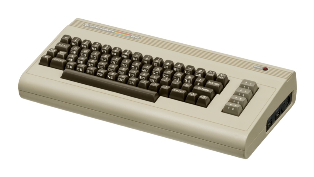
Commodore 64 — photo by Evan-Amos, domaine public (Wikimedia Commons).
Identification / models
| Model | Year | Note |
|---|---|---|
| C64 ("breadbox") | 1982 | the classic, "long board" |
| C64C | 1986 | slim case + short board (85xx chips) |
| SX-64 | 1984 | portable version with screen + built-in drive |
| C64 Games System | 1990 | console → dedicated page |
Architecture
| Block | Chip | Role |
|---|---|---|
| CPU | MOS 6510 (8500) | ~1 MHz |
| Video | VIC-II (6567/6569 · 8565) | 320×200, 16 colours, hardware sprites |
| Sound | SID (6581 12 V · 8580 5 V) | 3 voices + analog filters (the cult chip) |
| Logic | PLA (906114 · 8721), 2× CIA 6526, 64 KB RAM | glue, I/O, memory |
Repair (technician)
C64 power supply (the killer brick)
The original PSU ages badly: when its 5 V regulator fails it over-volts and kills the chips (RAM, PLA, SID, VIC). Do not trust a period brick: measure the 5 V, or switch to a modern PSU with overvoltage protection. This is THE cause of dead C64s. → Recap.
- Socketed chips: diagnose by substitution (RAM, PLA 906114, SID, VIC, 6510, CIA); PLA and SID are frequent failures.
- SID: 8580 (5 V) or 6581 (12 V) per board — mind the voltage on a cross-swap.
- Cartridge (expansion port) / serial (IEC) contacts: IPA clean.
- Recap if sound (SID) or video degrade.
- Video output: A/V DIN (Luma/Chroma/composite) → clean S-Video/RGB (video mods).
Original service manual ✅
Manufacturer manual archived locally. It typically carries the schematics, the block diagram, the expected voltages and waveforms, the parts list and the disassembly procedures — the reference when a symptom matches no known fault.
-
C64 — service manual 314001-02 (1985) — PDF
-
C64 / C64C — service manual 314001-03 (1992) — PDF
- C64 — PDF
Status
A manufacturer document with no explicit licence, kept for preservation (machine long out of production) — the same position as for the cabinet and arcade manuals already archived here. Source: Internet Archive.
Before you open it
Unplug the power supply and wait. The C64's external power brick is notorious for killing chips as it ages — if the machine has a display or RAM fault, suspect the power supply before removing anything. The chips are socketed on many boards: they come out without a soldering iron, but an extractor saves you from bending the pins.
Step-by-step disassembly procedures ✅
5 procedures transcribed from the iFixit guides, with difficulty and estimated time.
| Procedure | Difficulty | Time |
|---|---|---|
| Commodore 64 Opening the Case Prerequisite Guide | Moderate | 1 minute |
| Commodore 64 3AG fuse Replacement | Very easy | 1 minute |
| Commodore 64 Central Processing Unit (CPU) Replacement | Easy | 1 minute |
| Commodore 64 Removing the Shift-Lock Key | Moderate | 5 minutes |
| Commodore 64 VIC Chip Replacement | Very easy | 1 minute |
Commodore 64 Opening the Case Prerequisite Guide
The Commodore 64, also known as the C64, C-64, C= 64, or occasionally CBM 64 or VIC-64, is an 8-bit home computer introduced in January 1982 by Commodore International.
- Remove three 6.75mm ph2 screw heads from the casing
- Split the case of the C64 open by pulling up on the case towards you
- Do not pull too hard that you break the clips.
Commodore 64 3AG fuse Replacement
A 3AG fuse is a glass - bodied fuse designed to break an electric circuit if the current exceeds safety levels in a Commodore 64 device
- Remove three 6.75mm ph2 screw heads from the casing
- Split the case of the C64 open by pulling up on the case towards you
- Do not pull too hard that you break the clips.
- Detach the multi-colored wire bundles that's connected to the motherboard
- In this picture, the power indication LED (connected to the black and red wires) is not fastened to the keyboard panel, yours might be different.
- Find the 3AG fuse located next to the joystick ports and On/Off switch
- Using the ifixit splugger, prop out the 3AG fuse from the clip.
- — Replace the 3AG fuse by inserting the new fuse and letting it pop into the clip
Commodore 64 Central Processing Unit (CPU) Replacement
The Central Processing Unit (CPU) or Micro Processing Unit (MPU) is the 8-bit processor for the Commodore 64.
- Remove three 6.75mm ph2 screw heads from the casing
- Split the case of the C64 open by pulling up on the case towards you
- Do not pull too hard that you break the clips.
- Detach the multi-colored wire bundles connected to the motherboard.
- Locate the CPU chip which is labeled 'MOS 6510 3782'
- Loosen the CPU chip with a Phillips screwdriver. Then use your hand to pry up the CPU chip from the motherboard.
Commodore 64 Removing the Shift-Lock Key
The Commodore 64, also known as the C64, C-64, C=64, or occasionally CBM 64 or VIC-64, is an 8-bit home computer introduced in January 1982 by Commodore International.
- Remove three 6.75mm ph2 screw heads from the casing.
- Split the case of the C64 open by pulling up on the case towards you
- Do not pull too hard that you break the clips.
- Remove eight 6.75 mm ph2 screw heads to detach the keyboard face from the front casing. (Two remaining screws on the right side.)
- Remove twenty-three 3.38 mm ph2 screw heads from the back of the keyboard facing
- Detach the multi-colored wire bundles connected to the motherboard
- Next, carefully cut the two small wires which are connected from the Shift/Lock key to the keyboard.
- Turn the keyboard down on its face and push the shift lock key out from the back of the keyboard.
- You can remove the circuit component (gray piece attached to the shift lock key spring) by pulling back slightly on its clip and pulling it apart from the shift lock key button.
- — Take off the shift key button from the spring by using any Philips screwdriver to pry it off from the spring.
Commodore 64 VIC Chip Replacement
The Video Interface Controller (VIC) is is the graphics chip for the C64.
- Remove three 6.75mm ph2 screw heads from the casing
- Split the case of the C64 open by pulling up on the case towards you
- Do not pull too hard that you break the clips.
- Detach the multi-colored wire bundles that's connected to the motherboard
- Without using any tools prop up the metal VIC plate with both hands to expose the VIC chip.
- Use a Phillips screwdriver to pry up the VIC chip. Then, use your hands and with small pressure pull it away to remove it from the motherboard.
- You can insert a new VIC chip by making it clip back in on the board
Source, licence and scope
iFixit guides, under Creative Commons BY-NC-SA — attribution, non-commercial, share-alike. Only the text is reproduced; the step photos stay on iFixit. ⚠️ These guides target the model named in the title: on another revision, the screws and the order of removal may differ.
Procedure — a dead computer, step by step ✅
What this adds
Ordered for a home computer: what kills these is its power supply, its battery, its capacitors, its socketed RAM and its keyboard — roughly in that order, and well before the CPU. → PCB diagnosis
1. The power supply — measured before it is plugged in. This is the one step not to swap around. On a machine of this age a supply does not simply stop: a 5 V regulator that fails high puts 7, 9, 12 V onto the bus and takes the RAM and the custom chips with it. Measure every rail off the machine, under a dummy load if you can, and only then plug it in.
2. The battery, if it has one. Any RTC or backup cell soldered to a board is a future leak. If yours has one and it has never been changed, take it out before it takes the tracks with it. → Backup batteries
3. Capacitors. Recap is the default on these machines, not a last resort — and on the supply first, since that is what protects everything else. → Recap
4. RAM, on its sockets. These machines were built to be repaired: the RAM, and often the logic, sit in sockets. Reseat everything first — thirty years of oxide is a classic no-boot. Then swap chips: a bad RAM chip usually gives a repeatable pattern of garbage or a screen frozen at a fixed character.
5. The keyboard. A console does not have one; a computer's is a wear part. A membrane keyboard fails as whole dead rows or columns — that is the membrane, not the machine. A mechanical one wants its contacts cleaning, not replacing. Check this page: the failure mode is often documented per model.
6. Storage — tape or disk. Both often come down to the same things: a dirty head, and for tape the azimuth and a belt turned to tar. ⚠️ On the floppy side, check whether the mechanism actually has a belt before looking for one: many do, but some drives are direct drive, and hunting a belt that isn't there means stripping a drive for nothing. A machine that boots but loads nothing is a drive fault, not a logic fault — do not go looking on the board for it.
7. Video output. RF, composite, RGB or a dedicated monitor, depending on the machine (see Identification). Test with something else before you conclude: a period modulator and a modern TV disagree far more often than either is broken.
8. Still nothing. Now the logic: rails on the board, reset, clock, bus. → PCB diagnosis
Common faults
| Symptom | Likely cause | Lead |
|---|---|---|
| Console dies after a while | PSU over-volted the 5 V | Replace PSU; test chips |
| Garbage screen / won't boot | PLA or RAM dead | Substitute PLA, RAM |
| No sound / wrong sound | SID | Replace SID (correct voltage) |
| Dead ports | CIA 6526 | Substitute the CIA(s) |
| Cartridge not read | expansion-port contacts | Clean |
Modernisation & mods — what to buy, how
The 'killer' PSU: replace it BEFORE powering on
The original PSU over-volts the 5 V rail when its regulation fails → fries the CPU/PLA/RAM/SID in one go. A modern regulated PSU with overvoltage protection is essential (or a 5 V fuse/crowbar protector) before any power-up.
Modern storage (IEC bus) - SD2IEC 🟢 (cheap SD), Pi1541 🟢 (emulates a real 1541, max compat), 1541 Ultimate II+ 🟢 (disk + cartridge + REU); Kung Fu Flash / EasyFlash 🟢 (SD cartridge); JiffyDOS 🟡 (ROM swap/socket) speeds up access. All plug into the cartridge port or IEC — no soldering. - Ultimate 64 🟢: full FPGA recreation (replacement board) → adds an HDMI output.
Video - S-Video/composite mods (Lumafix et al.) 🟡 for a clean image on the stock C64.
Reliability - Recap 🟠; PLA and SID often socketed → easy substitution with modern reissues (ARMSID/SwinSID, PLAnkton) 🟢; clean cartridge/keyboard contacts.
⚠️ Do not host ROMs/games — method only.
See also
- C64GS (console version) · Amiga · Recap · PCB fault-finding.
Sources & attribution
- Photo Commodore 64 — Evan-Amos, domaine public, Wikimedia Commons — https://commons.wikimedia.org/wiki/File:Commodore-64-Computer-FL.jpg
- Wikipedia — Commodore 64 (6510, VIC-II, SID, PLA, models) — CC-BY-SA — https://en.wikipedia.org/wiki/Commodore_64
- Established C64 community knowledge (killer PSU, socketed PLA/SID, substitution) — synthesis.

Review & corrections
How this space is used
Spotted a wrong value, an outdated procedure, a chip reference that does not match your board? Say so here, with what you observed (model, board revision, serial number, measurement). Every report is cross-checked against a source before anything changes — an unverifiable correction is published as “reported by …, not cross-checked” rather than silently applied.
Reading is open to everyone; posting requires signing in with Discord. Reports from the wiki's declared reviewers are handled first; anyone else's are read too, but go through a human before anything is changed.