Power supplies in cabinets
How a cabinet turns mains into DC +5 V / +12 V / −5 V for the PCB, monitor, audio and lighting. Overview of the PSU types, the mains → DC rails chain, the adjustment and the safety. For hands-on teardown/recap of a Sega block: candy cab PSU repair.
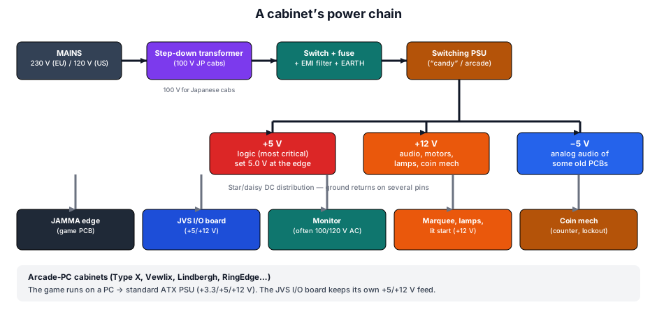
The rails and their role
| Rail | Use | Note |
|---|---|---|
| +5 V | logic (CPU, ROM, RAM, TTL), I/O inputs | most critical: high current, drop-sensitive → adjust at the edge |
| +12 V | audio amp, motors / force feedback, lamps, lit start, coin mech | wider tolerance |
| −5 V | analog audio of some old PCBs (DAC/filters) | often unused, but essential for a few games; first stage to fail |
| +3.3 V | modern boards / arcade PCs (via ATX) | absent from classic candy cabs |
| GND | common ground | several pins in parallel (+5 V return current) |
Power-supply types
| Type | Where | Outputs | Notes |
|---|---|---|---|
| Sega/Taito "candy" PSU | Astro/Blast/Egret… | +5 V, +12 V, −5 V | dedicated switcher, +5 V trimpot → repair |
| Generic arcade PSU ("switcher") | JAMMA cabs, superguns | +5 V (10–16 A typ.), +12 V, sometimes −5 V | the common blue/green brick; 110/220 V input (often a selector) |
| ATX PSU (PC) | Type X, Vewlix, Lindbergh, RingEdge… | +3.3 / +5 / +12 / −12 V | the game is a PC → standard PC PSU; the JVS I/O keeps its own feed |
| High-power / three-phase PSU | motion cabs (R360, deluxe) | logic + motors | high power, safety systems critical (see R360) |
| Linear PSU (transformer) | old cabinets | +5 V, +12 V | heavy, big transformer + rectifier + regulator; period-correct |
The mains chain (input)
- Mains: 230 V (EU), 120 V (US), 100 V (Japan).
- Step-down transformer: required for a 100 V Japanese cabinet on 230 V → step-down (ideally isolated). Some cabs have an internal multi-voltage transformer to set to the right tap.
- Main switch + fuse + EMI filter + earth (chassis bonded to earth — safety).
- PSU block: rectifies and switches to the DC rails.
Earth and mains — safety
The metal chassis must be bonded to earth. Never run a cabinet without earth. The transformer primary and PSU input are at mains potential (lethal); unplug and let the capacitors discharge before any work. On a 100 V cab, an isolated step-down is recommended.
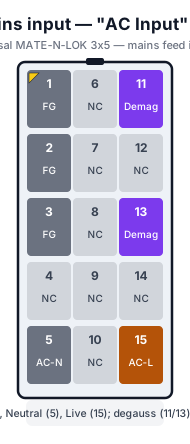
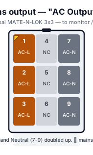
On Sega candy cabs the AC also runs through AMP Universal MATE-N-LOK connectors (same family as the DC). "AC Input" (15-pin) feeds mains into the PSU; "AC Output" (9-pin) redistributes it (monitor, accessories):
Low mains: the cabinet does not crash, it refuses the coin ✅
This whole page is about the DC side. One manufacturer put a number on the AC side, and the symptom it describes does not look like a power fault. Bally/Midway's Standardized General Instructions (© 1983) — the sentence is identical in all five manuals of that family archived here:
"Your machine must have the correct line voltage to operate properly. If the line voltage drops too low, a circuit in the computer will disable game credit. The point at which the computer will fail to work will vary some from game to game, but no game will work on line voltage that drops below 105 VAC."
⚠️ 105 VAC is a floor, not a tolerance. And the first thing to go is the credit: a coin mech that stops crediting is therefore not necessarily a coin mech problem.
ⓘ The causes the manual lists — all diagnosable without taking anything apart:
| Clue | What the manual says about it |
|---|---|
| The fault tracks the time of day | mains voltage fluctuates; peaks fall "mainly at dawn or dusk" |
| The fault follows a large start-up | a heavy load on the same line (air conditioner, large motor) drops the voltage on starting → intermittent credit |
| A bar with dimmed lighting | "location owners (especially in bars) replace light switches with dimmer rheostats, and the game is sometimes on the same line" |
| Permanent, not intermittent | cold solder joints in the harness — transformer connections, interlock switch, fuse block; location wiring, plug, line cord |
✅ The measurement, as the manual prescribes it (117 V North American mains):
- VOM on the 250 VAC range, probes in the wall receptacle.
- If the outlet is good → measure at the transformer primary connections.
- No 117 VAC at the primary → examine the solder joints on the transformer, fuse block and interlock switch.
- 117 VAC present → the fault is in the transformer, the harness connections, or the PCB power supply.
- To check the secondaries: VOM on 50 VAC, and correlate the readings with the legend on the side of the transformer — ⓘ the manual gives no table, it points at the part's own markings.
ⓘ One more symptom, and it is a visual one: the manual ties a rolling hum bar on screen to the transformer's ground potential — "The transformer must also be correctly grounded, so check the ground potential as well, especially if there is a hum bar rolling up or down the TV screen."
⚠️ These figures are those of a 117 V grid
105 VAC and 117 VAC describe the North American mains of 1983. They do not transpose as such to a cabinet wired for 230 V or a Japanese 100 V cabinet: it is the primary tap position that must match the local grid (see above). ⓘ What does transpose is the reasoning — low mains shows up first as a refused credit, not as a crash.
What boards actually demand on +5 V ✅
✅ Manual figures, where this page gave none
ⓘ This page openly stated it would give no currents — "exact specifications = the cabinet's manual, not invented". ✅ Here are those specifications, taken from the manuals archived here.
What the board demands — the requirement written by the game's maker:
| Board | What the document writes | Source |
|---|---|---|
| Atari Pit Fighter | +5 VDC ± 0.25 V @ 3.0 A · +12 VDC @ 1.0 A · −5 VDC @ 1.0 A (optional) | manual |
| McO'River Aero Fighters | +5 VDC @ 3 A and +12 VDC @ 1 A | manual |
| Namco Tekken 2 | 150 W, +5 VDC ± 5 %, 5 A min | manual |
| Namco Tekken 3 | 150 W, ⚠️ +5 VDC +5 % −1 %, 5 A min | manual |
| Johnny Nero Action Hero | +5 VDC @ 6 A (min) · −5 VDC @ 0.1 A (min) · +12 VDC @ 3 A (min) | manual |
| Konami Sunset Riders | GND-Vcc 5V 4A or more · GND-(+12 V) ⚠️ no current given | manual |
| Konami Vendetta | 5 V, 4 A or more | manual |
| Konami Turtles in Time | 5 V, 4 A or more | manual |
| Konami Bottom of the 9th | 5 V, 5 A or more | manual |
| Konami Open Golf Championship | 5 V, 5 A or more | manual |
ⓘ Konami has a house wording, identical from one manual to the next: "Required power capacity — GND-Vcc 5V 4A or more — GND-(+12V)". ⚠️ The +12 V is named but never given a current, and the +5 V is stated as a minimum, never as a tolerance band: nothing like Tekken 3's +5 % −1 %, which bounds the voltage itself. ⓘ Two makers, two ways of specifying the same supply.
What the cabinet supplies — the fitted unit, taken from the parts list:
| Cabinet | Power supply unit | Source |
|---|---|---|
| Sega Power Drift | 400-5089, SW REGU AC 90–240 V → +5 V 12 A | manual |
| Namco Motocross Go! Deluxe | 83000001, Switchmode 5 V 30 A | manual |
| Namco Panic Park | 83000008, Switchmode 5 V 32 A | manual |
⚠️ The two tables do not compare row for row: the first is a minimum required by a board, the second the capacity of a unit in a cabinet. ⓘ What can be read: the documented kits ask for 3 to 6 A on +5 V, the documented cabinets fit units of 12 to 32 A. ⚠️ So "a JAMMA power supply" says nothing about the available margin — both figures are needed.
⚠️ Correction of 13 September: two rows removed
⚠️ The first version of this table carried two wrong values, read from the text layer without re-reading the image:
- ICE Fire Escape "+5 V @ 1 A" — ⓘ that is row 991-045309-001 "IC Volt Reg. + 5V @ 1A" of the parts list: the rating of a regulator fitted on the board, not the game's power requirement.
- Taito Grand Champion "+5 V 1 A" — ⓘ that is a pinout row: pin 1 and pin A carry +5 V. It is not a current.
⚠️ They underpinned the claim "from 1 A to 32 A, a factor of thirty-two", withdrawn with them. The tables above now also separate a board's requirement from a unit's capacity, which the first version mixed.
⚠️ Namco tightened its tolerance between Tekken 2 and Tekken 3
ⓘ Two consecutive kits, same box, same 150 W unit, same 5 A, same +12 V ± 5 %. ⚠️ One line changes:
| +5 V | which is, computed here | +12 V | |
|---|---|---|---|
| Tekken 2 | ± 5 % | 4.75 – 5.25 V | ± 5 % |
| Tekken 3 | ⚠️ +5 % −1 % | ⚠️ 4.95 – 5.25 V | ± 5 % |
⚠️ The tolerance is asymmetric, and it bites downwards: Tekken 3 still accepts 5.25 V, but nothing below 4.95 V, where Tekken 2 went down to 4.75 V. ⓘ That is exactly what a long loom eats — hence the insistence, just below, on setting the voltage at the board edge and not at the supply output.
ⓘ Both values were re-read from the scan image: three characters separate the two manuals, and a text layer is not enough to settle it.
⚠️ A cabinet can set a ceiling, and write it out in full
The Taito Vewlix manual gives the capacity of its "new JAMMA" power kit — DC 12 V 4 A, 5 V 10 A, 3.3 V 12 A — then adds:
"この値以上の容量を必要とするゲームボードは、絶対に使用しないでください。これを怠ると 思わぬ事故の原因となります。" ⓘ Translated here: "Do absolutely not use a game board requiring more than these values. Failing to observe this may cause an unexpected accident."
ⓘ Note that 3.3 V is rated higher than 5 V — 12 A against 10 A. ⚠️ That is the signature of JVS-era boards, whose logic moved to 3.3 V; on a cabinet of this generation, the historic rail is no longer the main rail.
⚠️ The SCR crowbar: a collapsed output may be a circuit that did its job
Taito linear supplies of this era carry an SCR crowbar circuit — a thyristor that short-circuits the rail as soon as the voltage rises too far. ⓘ The manuals give both thresholds, and they are not the same rails:
| Rail | Factory setting | Components | Trips |
|---|---|---|---|
| +5 V (Qix) | 5 V ± 0.25 V at 7 A | Q8, D3, R20 | ⚠️ above 5.8 V |
| +12 V (Zookeeper) | 12 V ± 0.25 V at 4 A | D7, Q9, R31 | ⚠️ at 13 V, then foldback |
"Q8, D3 and R20 comprise a SCR-Type Crowbar Circuit which will trigger when the DC output voltages rise above 5.8V. Once the SCR fires, the Power Supply has to be turned off to reset the device." — Taito Qix
"D7, Q9, and R31 are SCR Crowbar Circuits which trigger at 13VDC output which causes supply to go into current foldback." — Taito Zookeeper
⚠️ Consequence for troubleshooting: on these units, an output that collapses and only comes back after a power-off is not necessarily the fault — it may be the protection having worked. ⓘ Powering back up without finding why the crowbar armed sends the overvoltage back next time. The defect is upstream, in the regulation.
⚠️ Correction of 13 September: the first version spoke of a blown fuse. ⓘ Neither manual says so — they describe a power-off needed to reset (Qix) and a fall into foldback (Zookeeper). The fuse was an extrapolation, withdrawn.
Adjusting +5 V (important)
Set +5 V AT THE EDGE (JAMMA/JVS), not at the PSU output
The harness drops voltage. Adjust the trimpot to read ~5.0 V where the board sees it (JAMMA edge or JVS I/O input), under load (game connected). Too low → crashes / corrupted sprites; too high (> 5.25 V) → risk to the PCB. Higher-end PSUs have remote sense that compensates the drop automatically.
DC distribution
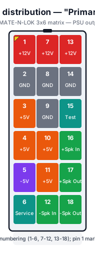
On Sega candy cabs (Astro/Blast/Net City, Naomi Universal) the PSU output leaves on an 18-pin "Primary DC" connector of the AMP Universal MATE-N-LOK family (3×6 matrix). It carries the +5 V / +12 V / −5 V rails, grounds, the Service line, a Test point and the speaker return (audio comes out of the PSU):
Reminder
It is a keyed connector: no risk of reversal, but check the voltages with a meter before plugging a PCB (see Adjusting +5 V).
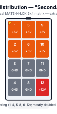
A 12-pin "Secondary DC" (same family, 3×4 matrix) sometimes supplements the distribution — essentially doubled +5 V with GND, plus one +12 V pin:
- Star or daisy chain to: the JAMMA edge (PCB), the JVS I/O board (+5/+12 V), the monitor (often powered separately from 100/120 V AC), marquee/lamps/lit start (+12 V), the coin mech (counter, lockout).
- Wire gauge: +5 V draws the most current → adequate wire and several GND pins in parallel (as the JAMMA pinout provides).
- Common ground: the same ground must tie PSU, PCB and panel (see the control panel's daisy-chained ground).
Common faults
| Symptom | Likely cause | Lead |
|---|---|---|
| Nothing powers up | fuse, switch, transformer, PSU input | Check fuse + mains present at the PSU |
| Crashes / corrupted graphics | +5 V too low (harness drop) | Adjust +5 V at the edge under load |
| No / weak sound | +12 V (amp) or −5 V (analog) | Measure 12 V and −5 V |
| PCB burns out | +5 V too high (> 5.25 V) | Recheck the adjustment, drifting trimpot |
| Unstable voltages | tired output capacitors | Recap the PSU → repair |
| Hum / noise | missing earth, no common ground | Check earth + common ground |
See also
- Sega candy cab PSU repair — recap, adjustment, faults.
- JAMMA wiring — the power pins (+5/+12/−5 V, GND).
- JVS wiring — I/O board JST NH power.
- Sega R360 — a high-power motion cabinet case.
→ Repair: Sega candy PSU · Recap · PCB fault-finding.
Sources & attribution
- Namco — Tekken 2 and Tekken 3 Kit Manuals (+5 V tolerances compared, re-read from image) — PDF · PDF
- Taito — Qix and Zookeeper (SCR crowbars, 5.8 V and 13 V thresholds) — PDF · PDF
- Taito — Vewlix Diamond (ceiling DC 12 V 4 A / 5 V 10 A / 3.3 V 12 A) — PDF
- Arcade Otaku Wiki — candy cab PSUs, 100 V input, +5 V adjustment — https://wiki.arcadeotaku.com/w/JAMMA
- JAMMA standard — +5/+12/−5 V rails, GND — https://wiki.arcadeotaku.com/w/JAMMA
- NFG Games / GameSX — Sega City cabinet pinouts (18-pin Primary DC, AMP Universal MATE-N-LOK) — https://gamesx.com/wiki/doku.php?id=arcade:sega_city_cabinet_pinouts
- Internal pages: Sega PSU repair · JAMMA wiring · JVS wiring
Review & corrections
How this space is used
Spotted a wrong value, an outdated procedure, a chip reference that does not match your board? Say so here, with what you observed (model, board revision, serial number, measurement). Every report is cross-checked against a source before anything changes — an unverifiable correction is published as “reported by …, not cross-checked” rather than silently applied.
Reading is open to everyone; posting requires signing in with Discord. Reports from the wiki's declared reviewers are handled first; anyone else's are read too, but go through a human before anything is changed.