Game Boy / Game Boy Color¶
Nintendo's 8-bit handhelds: Game Boy (DMG, 1989), Game Boy Pocket (MGB) and Game Boy Color (CGB, 1998). A reflective stock screen (no backlight) → the star mod is the IPS screen. Recap useful on the GBC.
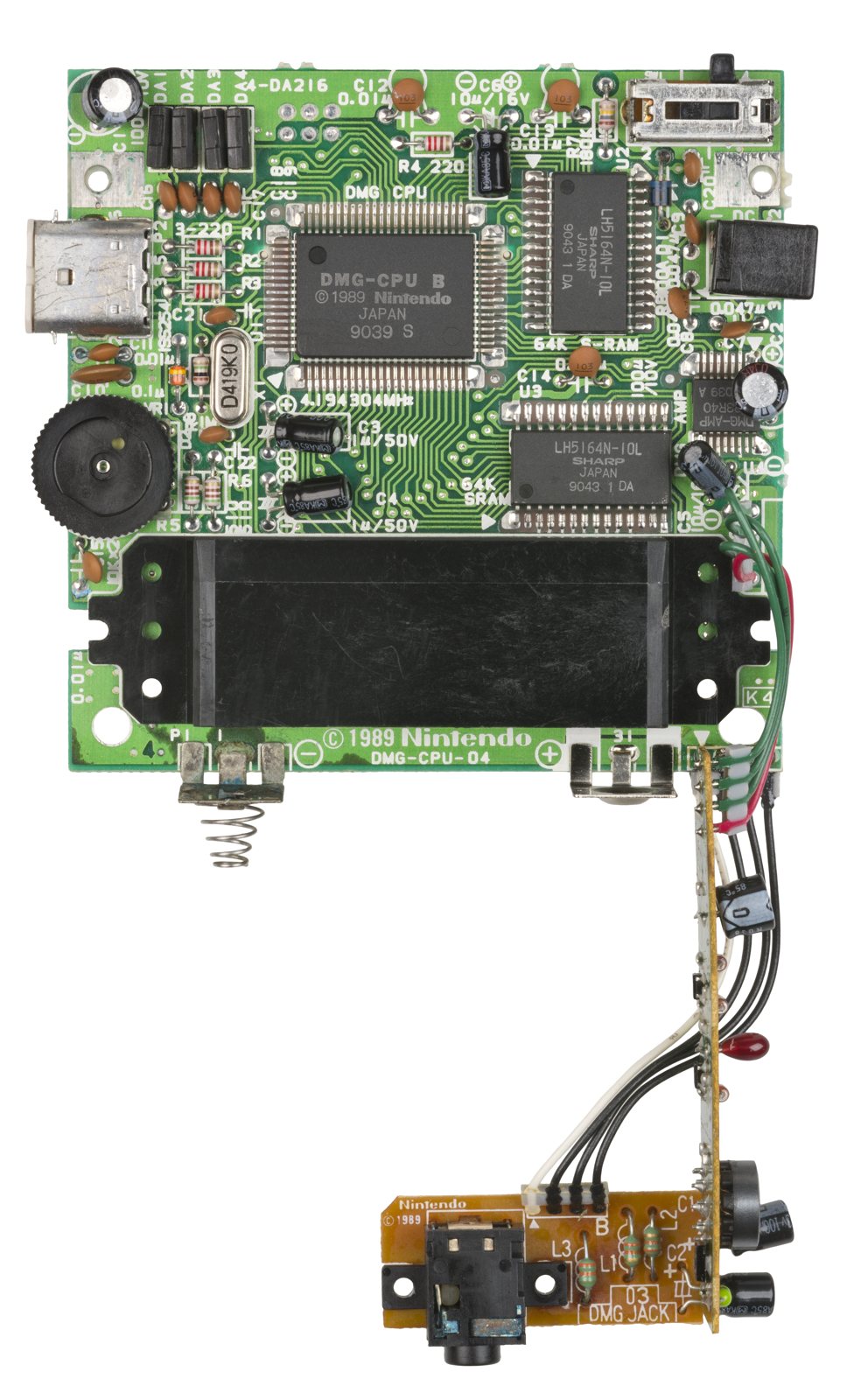
Identification¶
| Field | Value |
|---|---|
| Manufacturer | Nintendo |
| Releases | DMG 1989 · Pocket (MGB) 1996 · GBC 1998 |
| Type | 8-bit handheld |
| Screen | reflective LCD (DMG green; GBC colour) — no backlight |
| CPU | Sharp LR35902 (~4.19 MHz; ×2 on GBC) |
Architecture (detail)¶
| Block | Chip / value | Notes |
|---|---|---|
| CPU | Sharp LR35902 | 8080/Z80 hybrid (its own instruction set); 4.194304 MHz (DMG), ×2 = 8.388 MHz in GBC mode |
| LCD | 160×144 | DMG: 4 grey levels; GBC: 15-bit (up to 56 colours on screen / 32768 palette) |
| Sound | 4 channels | 2 pulse, 1 wave (32-sample RAM), 1 noise; stereo panning (headphones) |
| RAM | WRAM 8 KB (32 KB GBC) · VRAM 8 KB (16 KB GBC) | |
| Media | Cartridge + MBC | Mappers MBC1/2/3/5 (+ RAM + save battery, RTC on MBC3) |
Link (serial) cable for multiplayer / trades.
Models & backward-compatibility¶
| Model | Year | Screen | Note |
|---|---|---|---|
| DMG-01 | 1989 | "pea-soup" green, 4 AA | the original |
| Game Boy Pocket (MGB) | 1996 | sharp grey, smaller, 2 AAA | no backlight |
| Game Boy Light (MGB-101) | 1998, Japan | EL backlight | the only backlit official GB |
| Game Boy Color (CGB) | 1998 | 15-bit colour | ×2 CPU, DMG backward-compatible |
Board revisions — identification without disassembly ✅¶
Where to read the revision without opening the console
- DMG: the revision number is visible through the hole for the battery cover clip.
- Game Boy Pocket: revision readable under the left battery spring.
| Model | Revisions | What it means for the technician |
|---|---|---|
| DMG-01 | DMG-CPU-01 → -06 | 4 PCBs: CPU + LCD/control (sandwiched, FFC ribbon between them), a vertical DC-DC converter on the left, and a headphone jack board at the bottom. These revisions are largely identical; CPU and RAM are in soldered packages → replaceable. |
| DMG-01 | DMG-CPU-07 / -08 | ⚠️ Cost-reduced boards: the CPU and both RAM dies sit directly on the PCB under an epoxy blob ("glop top"). None of those chips can be replaced → repairability is greatly hampered. Check this before buying a DMG to repair. |
| GB Pocket | MGB-CPU-01 | Single board (VRAM integrated into the CPU). The no power-LED model. |
| GB Pocket | MGB-LCPU-01 / -02 | Models with the power LED (the LED returned in 1997). Mostly identical to each other. |
| GBC | CGB-CPU-01 → -04 | CPU revisions A to C: audio register bugs, different audio input impedance compared to later revisions, and increased background noise. In rare circumstances, crashes or other glitches. BennVenn's ElCheapo SD v2.0 flash cart has issues on these boards. |
| GBC | CGB-CPU-04 (late) | Some carry the revision D CPU, which fixes many of those bugs. The only way to tell: disassemble and look for a "D" on the CPU. |
| GBC | CGB-CPU-05 | All have the revision D CPU, otherwise identical to previous revisions. |
| GBC | CGB-CPU-06 | All RAM integrated into the CPU (revision E): the audio amplifier and the voltage regulator are the only remaining ICs. Revision E also resolves the bug introduced in D. |
Game Boy Light (MGB-101)
Based on the Pocket but slightly larger and running on AA batteries (hence better battery life than the Pocket even with the backlight on). The backlight is an electroluminescent (EL) panel — the kind used in some wristwatches, with a soft cyan glow — and not a fluorescent backlight like other backlit handhelds of the era. It can be switched off. The A/B labels are embossed into the buttons (not silkscreened on the shell): a handy authentication tell.
GBC cartridge colour code: a black shell = GBC-exclusive; a clear/coloured shell = a "dual-mode" game (colour on GBC, B&W on GB). The GBC also applies automatic palettes to old DMG games (boot button combos to change them).
Accessories & peripherals¶
- Game Boy Camera (VGA-ish B&W) + Game Boy Printer (thermal paper).
- Mobile Adapter GB (Japan): online play via a mobile phone (Pokémon Crystal, Mobile System GB) — a dead service.
- Super Game Boy: play on the SNES (see SNES § Add-ons).
- Pocket Sonar: a fishing-sonar cartridge (a Japanese curiosity).
Common faults¶
| Symptom | Likely cause | Lead |
|---|---|---|
| Vertical/horizontal lines (DMG) | LCD ribbon (failing adhesive) | Reflow the ribbon (heat) |
| Dark / unreadable screen | Reflective stock LCD | IPS screen (mod) |
| No sound / weak sound | Capacitors (audio), speaker | Recap; check speaker |
| Battery contact corrosion | Leaked batteries | Clean / rebuild the contacts |
| Won't power on | Power caps, contacts, fuse | Recap, contacts |
| Runs on mains, not on batteries | Failed DC jack (see box) | Metal contact cleaner into the jack, otherwise replace the jack |
| Batteries draining very fast | Dirty power switch | Properly clean the power switch |
| Crunchy / crackling audio | Power switch, headphone jack, caps | Clean the power switch; pipe cleaner + IPA in the headphone jack; full recap — especially C32 (GBC) |
| Loud whining noise | CleanAmp installed (notably with LEDs set to white on a button LED kit) | Remove the CleanAmp |
The DC jack trap: \"it no longer runs on batteries\"
The power jack carries a detection contact: when a plug is inserted, it shuts off the battery circuit. These jacks are known to fail and stay stuck in the "plug inserted" state — the console then refuses to run on batteries even though nothing is plugged in. Before suspecting the power section or the capacitors, treat the jack: metal contact cleaner, then replacement if it persists. (Source: ConsoleMods, CC-BY-SA.)
Step-by-step disassembly procedures ✅¶
7 procedures transcribed from the iFixit guides, with difficulty and estimated time.
| Procedure | Difficulty | Time |
|---|---|---|
| Game Boy Display Lines/Bars | Moderate | 30 seconds - 1 hour |
| Nintendo Game Boy Teardown | Moderate | 5 - 15 minutes |
| Game Boy Batteries Replacement | Very easy | 15 seconds |
| Game Boy Headphone Jack Replacement | Difficult | 30 minutes |
| Game Boy Outer Case Replacement | — | — |
| Game Boy Screen Replacement | Very difficult | 30 minutes - 1 hour |
| Game Boy Speaker Replacement | Difficult | No estimate |
Game Boy Display Lines/Bars
Fixing the common problem of lines/bars on the original Nintendo Gameboy.
- Remove the back housing by removing the 6 Tri-Point or Philip screws.
- Note: The last 2 screws are in the battery compartment.
- Carefully lift up the top half of the system. Be careful, there's a ribbon cable that connects the top and bottom half of the system.
- Remove the ribbon cable for the next step.
- Now there will be screws that mount the board to the front, carefully unscrew these.
- Now remove the board from the housing.
- Now put the batteries back into the compartment, so you can test the screen while you fix it.
- Reconnect the the board to back housing with the ribbon cable.
- You're now going to turn the contrast ( the slider on the left) all the way up, and take your soldering iron and gently move it back and forth on the ribbon cable below the screen.
- Make sure not to touch the screen itself.
- Note: There may be a rubber strip covering the ribbon.
- You will start to see the lines of pixels fade in and out, keep moving your iron back and forth until screen is completely black.
Nintendo Game Boy Teardown
Before there was the Switch, the Nintendo Game Boy line of handheld game consoles was the king of the streets. 30 years later, the original model still holds a special place in the hearts of on-the-go gamers. In honor of its 30th anniversary, we decided to travel back in time to see what made the original Game Boy tick. Want more teardowns? Follow us on Instagram, Twitter, and Facebook for all the latest teardown and repair news. For news delivered, sign up for our newsletter.
- While it wasn’t the first handheld game console to hit the market, the Game Boy popularized the category and kick-started the portable gaming industry.
- Tech Specs: (We will see these later!)
- 4.19 MHz 8-bit processor
- 8 KB of RAM
- 2.6" 160x144 STN LCD display
- Fun fact: the LCD display was only capable of displaying four colors. Of course, those colors were just varying shades of green.
- Denoted by model number DMG-01 (which stands for Dot Matrix Game), the Game Boy can be powered by either four AA batteries or an AC power adapter, the latter of which has unsurprisingly disappeared into the clutter abyss.
- Despite the one model number, the Game Boy came in a handful of different models over the years, with subtle differences to the circuitry.
- If you're wondering, that 800 number does still call Nintendo's support line, just in case you ever need some help with your retro handheld.
- The case is held together by six tri-point Y1 screws. Even back in 1989, Nintendo thought traditional screws might be too easy for us tinkerers. Fortunately, our Mako Driver Kit comes with the necessary bit.
- Do not take apart your Game Boy with standard Phillips or flathead screwdrivers. Doing so will strip your screws. If your screws are stripped, don't panic! Click here|new_window=true to fix it.
- Nintendo was at least nice enough to include an indentation for our driver to nicely fit into within the battery compartment.
- We slowly separate the two halves of the outer shell to reveal a ribbon cable booby trap! Luckily, this ribbon cable is way more robust than those you'll find in newer devices.
- A firm grab and pull of the ribbon cable is all that stands between complete front and back separation.
- Once we're inside, it's all standard Phillips screws from here on out. The display's circuit board is held down with ten of them.
- We slowly start prying from the top, as the display and circuit board are ever-so-slightly adhered to the case.
- Do not yank the board up. This may result in... something...
- The LCD display is attached to the circuit board with clips and a couple of screws. Unfortunately, the display's cable is soldered to the board, making display replacements a bit tricky.
- The speaker, which is typically a modular component in many devices today, is also soldered to the board. Fortunately, it's just two wires with simple solder points.
- The circuit boards inside the rear case are much easier to remove, with only four screws and no adhesive holding it down!
- The mainboard, power board, and jack board are connected together and come out all at once.
- As with the display and speaker wires, the headphone jack and other ports are all soldered to the boards.
- Enhance! Here's what's on the main board of our specific model:
- Sharp LR35902 4.19 Mhz CPU
- LSI Logic LH5264N4T 8 KB VRAM
- LSI Logic LH5264N4T 8 KB WRAM
- Sharp IR3R40 amplifier
- For some unknown reason, your board may have different chips. This may not mirror what's on your revision.
- We hope you enjoyed this trip down memory lane!
- Now, if you'll excuse us, we're going to put this thing back together and enjoy some Super Mario Land 2! Wahoo!
Game Boy Batteries Replacement
This guide will illustrate how to replace the batteries in a Game Boy system.
- Switch your Game Boy off and remove the cartridge.
- Use a fingernail (or small coin) to push down on the battery door latch and remove the battery door.
- The release latch is a plastic spring clip. If your Game Boy is getting on in years, be careful as the plastic may be brittle.
- When you're replacing the cover, be sure to get its two plastic tabs into the slots in the bottom of the battery compartment before pushing the cover back in place.
- Use a fingernail to pry each battery outward from the positive (+) terminal to remove them.
- Dispose of used batteries properly!
- Remove the batteries from your Game Boy before storing it for more than a month or so.
Game Boy Headphone Jack Replacement
This guide will illustrate how to install a new headphone jack on an original Game Boy system. You'll need to know how to solder for this replacement, so be sure to check out iFixit's soldering technique guide.
- Switch your Game Boy off and remove the cartridge.
- Use a fingernail (or small coin) to push down on the battery door latch and remove the battery door.
- The release latch is a plastic spring clip. If your Game Boy is getting on in years, be careful as the plastic may be brittle.
- When you're replacing the cover, be sure to get its two plastic tabs into the slots in the bottom of the battery compartment before pushing the cover back in place.
- Use a fingernail to pry each battery outward from the positive (+) terminal to remove them.
- Dispose of used batteries properly!
- Remove the batteries from your Game Boy before storing it for more than a month or so.
- Remove the six Triwing screws from the back of the device.
- Gently separate the device's front casing from the back casing after you remove the screws.
- Be careful not to completely separate the casing halves, as they are still joined by a large ribbon cable that may be damaged.
- Slide the front side of the casing down to expose the ribbon cable connector.
- Grip the ribbon connector with your thumb and forefinger. Pull down gently until the connector, not the ribbon itself, comes out of its socket.
- Separate the front and back casings.
- The headphone jack is located on the bottom of the rear outer casing, near the battery compartment.
- Use a Phillips #00 screwdriver to remove the two screws holding the headphone jack in place.
- Once the headphone jack is detached it will dangle by the wires attached to the main circuit board. Do not worry about the connections, they are solid and will not break.
- Use a Phillips#00 screwdriver to remove the two screws that hold the main circuit board to the casing. This will allow access to the connection points of the headphone jack.
- Use a plastic opening tool to remove the main circuit board from the casing.
- Once the main circuit board is removed, set aside the outer casing.
- Desolder the four wires connecting the headphone jack to the motherboard.
- Desolder the four wires connected to the headphone jack
- To learn more about soldering, check out iFixit's soldering technique guide.
- Remove the headphone jack with tweezers.
Game Boy Outer Case Replacement
This guide explains how to remove the outer...
- Switch your Game Boy off and remove the cartridge.
- Use a fingernail (or small coin) to push down on the battery door latch and remove the battery door. The release latch is a plastic spring clip. If your Game Boy is getting on in years, be careful as the plastic may be brittle. When you're replacing the cover, be sure to get its two plastic tabs into the slots in the bottom of the battery compartment before pushing the cover back in place.
- Use a fingernail to pry each battery outward from the positive (+) terminal to remove them. Dispose of used batteries properly! Remove the batteries from your Game Boy before storing it for more than a month or so.
- Remove the six Triwing screws from the back of the device.
- Gently separate the device's front casing from the back casing after you remove the screws. Be careful not to completely separate the casing halves, as they are still joined by a large ribbon cable that may be damaged.
- Slide the front side of the casing down to expose the ribbon cable connector.
- Grip the ribbon connector with your thumb and forefinger. Pull down gently until the connector, not the ribbon itself, comes out of its socket. Separate the front and back casings.
Game Boy Screen Replacement
How to access and replace the black and white LCD screen in your original Game Boy. This is an advanced repair. You'll need to know how to solder to complete this repair, so be sure to check out iFixit's soldering technique guide. Note: If your Game Boy’s display has the classic “vertical lines” problem, it’s actually easier to fix the old screen than to replace it with a new one. Follow this guide for help repairing the old screen.
- Switch your Game Boy off and remove the cartridge.
- Use a fingernail (or small coin) to push down on the battery door latch and remove the battery door.
- The release latch is a plastic spring clip. If your Game Boy is getting on in years, be careful as the plastic may be brittle.
- When you're replacing the cover, be sure to get its two plastic tabs into the slots in the bottom of the battery compartment before pushing the cover back in place.
- Use a fingernail to pry each battery outward from the positive (+) terminal to remove them.
- Dispose of used batteries properly!
- Remove the batteries from your Game Boy before storing it for more than a month or so.
- Remove the six Triwing screws from the back of the device.
- Gently separate the device's front casing from the back casing after you remove the screws.
- Be careful not to completely separate the casing halves, as they are still joined by a large ribbon cable that may be damaged.
- Slide the front side of the casing down to expose the ribbon cable connector.
- Grip the ribbon connector with your thumb and forefinger. Pull down gently until the connector, not the ribbon itself, comes out of its socket.
- Separate the front and back casings.
- Remove the ten screws that connect the circuit board to the outer case.
- Remove the circuit board from the outer case using a plastic opening tool.
- Take care to gently pry around the entire outside edge of the circuit board until you can easily remove the board without force.
- Disengage the the three plastic clips that secure the screen to the circuit board.
- Flip the circuit board over revealing the device screen.
- Remove the two screws connecting the screen and the circuit board.
- Follow the video instructions to desolder the display connectors and replace your screen.
Game Boy Speaker Replacement
This guide explains how to replace the speaker in a first-generation Nintendo Game Boy system.
- Switch your Game Boy off and remove the cartridge.
- Use a fingernail (or small coin) to push down on the battery door latch and remove the battery door.
- The release latch is a plastic spring clip. If your Game Boy is getting on in years, be careful as the plastic may be brittle.
- When you're replacing the cover, be sure to get its two plastic tabs into the slots in the bottom of the battery compartment before pushing the cover back in place.
- Use a fingernail to pry each battery outward from the positive (+) terminal to remove them.
- Dispose of used batteries properly!
- Remove the batteries from your Game Boy before storing it for more than a month or so.
- Remove the six Triwing screws from the back of the device.
- Gently separate the device's front casing from the back casing after you remove the screws.
- Be careful not to completely separate the casing halves, as they are still joined by a large ribbon cable that may be damaged.
- Slide the front side of the casing down to expose the ribbon cable connector.
- Grip the ribbon connector with your thumb and forefinger. Pull down gently until the connector, not the ribbon itself, comes out of its socket.
- Separate the front and back casings.
- Remove the 10 Phillips #00 screws from the motherboard.
- Use a plastic opening tool to gently lift the motherboard up and remove it from the front plastic case.
- Use caution when lifting the board since the speaker is attached.
- Desolder the two wires connecting the speaker to the motherboard.
- Remove the speaker.
- If you're new to soldering, refer to this guide|new_window=true for tips that will help with desoldering the speaker wires and/or soldering the new ones in place.
Source, licence and scope
iFixit guides, under Creative Commons BY-NC-SA — attribution, non-commercial, share-alike. Only the text is reproduced; the step photos stay on iFixit. ⚠️ These guides target the model named in the title: on another revision, the screws and the order of removal may differ.
Procedure — a dead console, step by step ✅¶
What this adds
Ordered for a console, not for an arcade board: what kills these is almost never the CPU. It is, in real order, the power supply, the capacitors, the drive or the cartridge slot, and only then the logic. → PCB diagnosis
1. The power supply. Two cases, depending on the machine. External brick: ⚠️ read the marking on the machine, next to the socket, and check the adapter against it — voltage and polarity. A centre-negative machine fed centre-positive loses its fuse, sometimes its regulator; do not trust a third-party label or a generic tip. Internal supply (the machine plugs straight into the wall): mains is inside the shell. Unplug, wait, and confirm the large capacitors are discharged before touching the board. Either way, measure under load: a failing supply holds its voltage until it is asked for current.
1b. Battery and its contacts. On this machine, before anything else: corroded battery contacts, or a cell that reads fine off-load and collapses under it, give exactly the symptoms of a dead machine.
2. The fuse. Many of these machines have one right behind the socket — it is the part designed to die. Test it in continuity, out of circuit. A fuse that blows again is a short, not a fuse problem.
3. Capacitors. On most machines of this age this is the default suspect rather than a last resort — leaking SMD electrolytics eat the tracks underneath before they give any other sign. ⚠️ Not all of them are like that: some carry very few and are not recapped on principle. Read what this page says about it before reaching for the iron. → Recap
4. The cartridge connector. Cartridge contacts with isopropyl alcohol, never an abrasive eraser: it takes the gold plating off and the problem comes back worse. On the machine side, inspect the slot pins — splayed, bent or oxidised — and check continuity between slot and board.
5. The screen. Lines, a dead half, a picture that fades: it is almost always the ribbon and its solder joints, not the panel. Reseat before you order anything. If this machine has a TV output — not all of them do — test that too: it tells the screen apart from what feeds it.
6. Still nothing. Now, and only now, the logic: rails on the board, reset, clock, bus. → PCB diagnosis
Region — there is nothing to do ✅¶
The entire Game Boy line is region free: Game Boy (DMG), Pocket, Light, Color, Advance, Advance SP and Micro. Regardless of the country the console was bought in, it plays the entire Game Boy library — without any region adapter or homebrew. There is therefore no region mod to perform on these machines. (Source: ConsoleMods, CC-BY-SA.)
Not to be confused with model compatibility
Being region free does not mean universal compatibility: a handful of Game Boy titles don't function correctly on later models (see the gbdev documentation). That is a hardware/revision issue, not a region one.
Popular mods — what to buy, where, how¶
Handheld tooling
Tri-wing (Y) + Phillips screwdrivers, fine-tip iron, thin wire, maybe a Dremel (to shave the shell for the IPS). Soldering: 🟢 none · 🟡 · 🟠 · 🔴.
Backlit IPS screen — THE mod¶
- Replaces the dim stock screen with a bright IPS (contrast, adjustable palettes, often brightness control). Per-model kits from FunnyPlaying, Hispeedido (DMG, GB Pocket, GBC).
- Install 🟡/🟠: open, swap the panel + flex; per kit, shave/drill the shell (the IPS is larger than the STN) and solder a thin wire for brightness/OSD. Many kits ship with a fitted shell (recommended for a first go). → Handheld IPS page.
- Bivert (DMG only): improves the stock STN contrast — superseded by IPS.
FunnyPlaying GBC IPS screen (2.0 Q5) — exact procedure 🟡¶
A laminated IPS panel for the Game Boy Color: 4× integer scaling, pixel display effects, brightness levels, and a configurable "GAME BOY COLOR" logo colour. An IPS-compatible custom shell is highly recommended — otherwise the original shell needs a lot of trimming.
Mod order
If you also plan the FunnyPlaying button LED kit, do that one first: it provides new Start and Select pads that the IPS screen will use. ⚠️ Known manufacturing defect: the Start and Select labels on the flex may be swapped → test continuity between the pads at the top of the flex board and the actual Start/Select pins at the bottom of the motherboard before soldering.
1. Motherboard prep — trim the cartridge port pins as flat as possible with flush cutters, then lay a piece of Kapton tape over them to rule out any short.
2. Test BEFORE using the adhesive (the manufacturer's warranty is void once you use it):
- Disassemble and remove the motherboard from the shell.
- Plug the screen's ribbon into the LCD connector, oriented with the Nintendo logo on the motherboard facing up and the STA / SEL pads on the flex facing down.
- Add solder to the "C" pin of the power switch, solder the provided short wire to it and the other end to the PWR pad on the flex ribbon.
- Power up (power plug, or back shell + batteries) and inspect: dead pixels, oddities → contact the vendor.
3. Installation — desolder the flex end of the PWR wire, disconnect the screen from the large flex ribbon, remove any adhesive in the middle of the flex, then apply the supplied black stickers (the strip over the copper area on the front, the large one over the back plus the copper area). Insert the screen from the front of the shell, ribbon routed through to the back, without creasing the ribbon or catching the bottom lip.
4. Start / Select wiring (motherboard laid in the front shell, screen facing down, Nintendo logo facing up):
| Without the button LED kit | From | To, on the motherboard |
|---|---|---|
| Select | SEL pad on the flex | right-most via of the group of 5 vias inside the large silkscreen rectangle |
| Start | STA pad on the flex | left-most via of the group of 3 vias inside the large silkscreen rectangle |
(With the button LED kit: SEL → the kit's Select pad and STA → its Start pad, after the continuity test above.)
5. Closing up — clip the large flex onto the screen's ribbon pressing only on the ribbons (never on the back of the screen). Refit the motherboard, fold the flex without creasing it, and tuck the small piece of flex sticking out — the touch sensor — up under the top of the shell. Resolder the PWR wire. Kit screws: 2 short ones for the motherboard, 7 long ones for the shell, and omit the battery-compartment screw (it risks cracking the front of the shell).
Usage (touch sensor)
- Tap = 7 brightness levels.
- Hold 3 s = 5 pixel display modes.
- Start+Select = "GAME BOY COLOR" text editing mode: GAME = vertical centring, BOY = horizontal centring, COLOR = text colour (Start/Select to cycle). Start+Select again to exit.
- Hold 10 s (touch sensor or Start+Select) = factory reset of the screen.
- Dead pixels noticed after installation may clear up after some use.
DMG backlight + bivert — exact procedure 🟠¶
Adding a backlight behind the DMG's stock STN panel. The bivert part (optional but highly recommended) greatly enhances visibility: without it you are simply lighting up a mediocre-contrast screen. (Original guide: Roarke for RetroRGB, via ConsoleMods CC-BY-SA.)
Bivert on IPS: pointless
On a replacement IPS screen, the bivert mod will not improve clarity or contrast — it only inverts the colours. Bivert is a mod for the stock STN panel.
Materials: backlight, bivert mod board, solder + flux, ChipQuik, solder braid, isopropyl alcohol 70-90%, a sharp razor blade, toothbrush and cotton swabs, tri-wing and Phillips screwdrivers, flush trimmers, heat shrink tubing, gloves (avoids smudging the screen).
Screen removal — 6 case screws (Phillips on earlier DMGs, tri-wing security screws on newer ones), carefully disconnect the ribbon between the LCD board and the motherboard, then 10 Phillips screws to free the LCD board. Rest it without putting any pressure on the ribbon.
Ribbons: the point of no return
The pins of the vertical and horizontal ribbons are extremely delicate and will break under any pressure. You never force anything: it is the ChipQuik that releases the ribbon on its own.
- The vertical ribbon is held by 2 small Phillips screws + a staple. Bend the staple's two legs upward on the back, remove the 2 screws, pry the staple up a little. One end of the staple is soldered: flux it, wick it with solder braid, then heat and gently pull it out. Then turn the iron down to 200 °C.
- Clean the ribbon pins with a cotton swab + IPA, moving in the same direction as the pins.
- ChipQuik (a knife tip is preferable): it lowers the melting point to about 180-200 °C and keeps the solder molten for longer. Flux, then lay a line of ChipQuik across the pins. Hold the iron with the bevel parallel to the board and perpendicular to the pin direction, melt the ChipQuik without ever letting the tip touch the pins. Rock the blob back and forth while gently supporting the ribbon from underneath with a small flathead: once everything has mixed, the ribbon lifts away by itself.
- Pry the screen up with a small flathead at the top (a notch in the plastic frame is provided), open it like a book while supporting the horizontal ribbon, and remove the 2 double-sided foam pieces. Remove the small black Phillips screw holding the horizontal ribbon and repeat the same removal — supporting the ribbon without pressing on it. Pinch the 3 clips of the plastic LCD frame on the back of the board and pop it off.
- ChipQuik decontamination (do not skip): set the iron back to 315-340 °C. On the board: flux, braid, then re-tin with standard solder and wick again — 2 to 3 times, to dilute and remove the ChipQuik (from here on it counts as a contaminant). On the ribbons: no braid (it would rip the pins off) — use a clean tip, place the bevel and brush away in the direction of the pins, clean the tip, re-tin, brush again, 2 to 3 times.
Component replacement (behind the LCD — 30-year-old parts, now or never):
| Reference | Replace with |
|---|---|
| C4 | 47 pF ceramic |
| C6, C7, C8, C9, C10 | Nichicon 1 µF / 50 V electrolytics |
| R2 | 100 Ω — 1/8 W resistor |
| DA1, DA2, DA3, DA4 | DAN215 diodes |
| Q1 | 2SA933 PNP transistor |
Testing the diode array and Q1 (with a multimeter, in circuit)
The diode array is responsible for button presses and must be healthy. With the LCD board disconnected from the motherboard and no button pressed, these diodes are connected to nothing else → they can be tested without removing them.
DAN215: pin 2 (the middle pin) is the common negative; pins 1 and 3 each have a diode between them and that common ground.
Multimeter in diode mode, negative lead on pin 2:
- Positive lead on pin 1 → expect a 700-725 mV voltage drop. Same for pin 3.
- A reading of "1" = an open diode (double-check your leads).
- A beep / continuity = a short.
- Repeat for DA1 to DA4, replacing as needed.
Q1 (2SA933, PNP) — remove it from the circuit to test. Pinout: 1 = emitter, 2 = collector, 3 = base. In diode mode:
| Test | + lead | − lead | Expected |
|---|---|---|---|
| Emitter → Base | Emitter | Base | 0.4 to 0.9 V |
| Collector → Base | Collector | Base | 0.4 to 0.9 V |
| Base → Emitter | Base | Emitter | over limit (OL) |
| Base → Collector | Base | Collector | over limit (OL) |
| Collector ↔ Emitter | (both directions) | over limit (OL) |
Any test out of spec → replace Q1.
Then clean the LCD board thoroughly (IPA + a clean toothbrush) and wipe before the alcohol evaporates (otherwise it leaves sticky flux residue). This is also the moment to leverage the rear polarising/reflective film without damaging the horizontal ribbon, to clean the inside of the screen corner to corner with a microfibre cloth.
Separating the screen (gloves recommended) — dip the razor blade in IPA, slide it between the LCD and the reflective film starting at a corner, bevel flat against the LCD, going in about 1/3 of an inch, until you can pinch the lifted corner. Then pull the film in one smooth gentle motion: the quicker and smoother the pull, the cleaner the screen. If the layers separate, start again from another corner. Leftover adhesive → cotton swab + IPA, then a paper towel dipped in alcohol, a dry one, and compressed air.
Horizontal lines: this is when you address them
With the screen open is the time to address any horizontal line issues. ConsoleMods points to a video tutorial on RetroRGB's channel — their Vertical/Horizontal Lines on Screen pages are empty to this day, so no written procedure is reproduced here rather than inventing one.
Bivert (optional) — first, if fitting the bivert: take the supplied polarising film and hold it up to a light; if it doesn't appear dark, rotate it 90 degrees. Remove its protective film and place it between the LCD and the backlight.
Then, on the ribbon cable port:
- Gently heat and lift pins 6 and 7 of the ribbon cable port.
- Slide the bivert board under the lifted pins, aligning those pins as well as VCC, PIN1 and PIN3. ⚠️ The board will hang off the edge of the board — that is normal.
- Solder the two lifted pins, then the VCC, PIN1, PIN3 and GND joints. Using flux is what avoids bridges between the two lifted pins.
(Original images: The Retro Mechanics.)
Refitting the screen — pop the frame back onto the board, flux the pads, position the horizontal ribbon, screw its set screw in partially, tack the pins with the bevel of the iron, then screw it in fully and reflow the pins. Clean the flux (cotton swab + alcohol).
Installing the backlight:
- Solder two wires to the backlight's positive and negative pins if it doesn't already have them.
- Slide the backlight behind the screen BEFORE resoldering the vertical ribbon — it is a bit thicker than the space beneath the screen; soldering the ribbon first would put permanent tension/stress on its pins, which will cause problems down the road.
- Close the screen and resolder the vertical ribbon.
- Powering the backlight — your options: a backlight controller, C2, directly on the
DC-DC board, or ideally an auxiliary 5 V buck/boost regulator to power all mods.
The easiest remains C2:
- negative wire → right-hand pad of the capacitor below the screen;
- positive wire → the supplied resistor (leads trimmed short) → left-hand pad of that same capacitor.
- Test with batteries in before fully reassembling.
Audio — prosound (chiptune)¶
-
Prosound: a clean line-out (essential for LSDj / Nanoloop, the DMG being the king of chiptune). Often paired with a better output cap.
-
Two variants: pre-pot (audio at fixed full volume, the wheel does nothing) or post-pot (volume set by the wheel). The left/right audio is tapped at the volume potentiometer; ground is shared with the headphone jack (nothing extra to wire). (Per the RetroModding tutorial.)
-
⚠️ The exact pot leg depends on the DMG revision and is shown in illustrated guides/kits (RetroModding, prosound boards with L/R pads) — not copied/invented here for lack of an open-licensed pinout. Safest: a prosound board with labelled L/R pads.
-
Power / library¶
- USB-C / rechargeable battery: internal charging kits (replace the AA cells).
- Flashcart: EverDrive-GB / GB X7 (Krikzz) or EZ-Flash Junior — library + homebrew on SD, plug-and-play 🟢.
Recap¶
- Capacitor replacement (especially GBC/GBA): restores sound and reliability → CXX tables below (Console5 source).
Save RTC (MBC3)
MBC3 cartridges (Pokémon Gold/Silver/Crystal) have a real-time clock backed by a battery: a dead battery = lost time-based events (berries, in-game time). Replace the battery in the cartridge (soldered).
Capacitor list (per board & CXX reference) ✅¶
Source: Console5 TechWiki. CXX references = location on the board.
Game Boy DMG-01 (rev. -06) — 16 caps¶
CPU board (DMG-CPU-06):
| Ref | µF | V |
|---|---|---|
| C1, C2 | 100 | 10 |
| C3, C4 | 1 | 50 |
| C5, C6 | 10 | 16 |
LCD board (DMG-LCD-06):
| Ref | µF | V |
|---|---|---|
| C1, C2 | 100 | 10 |
| C3 | 10 | 25 |
| C6, C7, C8, C9, C10 | 1 | 50 |
Headphone jack board: C1, C2 = 100 µF / 6.3 V.
Game Boy Color (CGB-001) — 3 caps¶
| Ref | µF | V |
|---|---|---|
| C32 | 100 | 6 |
| C35 | 22 | 16 |
| C38 | 100 | 4 |
Pinouts ✅¶
Link cable — DMG-07 / DMG-04¶
The DMG-04 is the large connector of the original DMG; the DMG-07 is the small one (Pocket / Color / adapters).
| Pin | Name | Description | DMG-07 colour | DMG-04 colour |
|---|---|---|---|---|
| 1 | VCC | 5 V | Brown | — |
| 2 | SO | Serial Out | Red | Red/Orange |
| 3 | SI | Serial In | Yellow | Orange/Red |
| 4 | SD | CPU pin 14 | — | — |
| 5 | SC | Clock | Green | Green |
| 6 | GND | Ground | Blue | Blue |
| S | Shield | Ground (shield) | Bare | Bare |
Cartridge port — 32 pins¶
Pins numbered left to right, cartridge label up.
| Pin | Function | Pin | Function | Pin | Function | Pin | Function |
|---|---|---|---|---|---|---|---|
| 01 | +5 V | 09 | Address A3 | 17 | Address A11 | 25 | Data D3 |
| 02 | CLOCK | 10 | Address A4 | 18 | Address A12 | 26 | Data D4 |
| 03 | WRITE | 11 | Address A5 | 19 | Address A13 | 27 | Data D5 |
| 04 | READ | 12 | Address A6 | 20 | Address A14 | 28 | Data D6 |
| 05 | CHIP SELECT | 13 | Address A7 | 21 | Address A15 | 29 | Data D7 |
| 06 | Address A0 | 14 | Address A8 | 22 | Data D0 | 30 | RESET |
| 07 | Address A1 | 15 | Address A9 | 23 | Data D1 | 31 | AUDIO IN |
| 08 | Address A2 | 16 | Address A10 | 24 | Data D2 | 32 | GROUND |
What this is for on the bench
A classic 8-bit data / 16-bit address bus: you can check continuity of the cartridge port pins back to the board (the number-one cause of "cartridge not detected" after cleaning), and pin 31 AUDIO IN explains cartridges with extra sound hardware. (Source: ConsoleMods, CC-BY-SA.)
Photos / assets¶
(To add: DMG vs GBC board, LCD ribbon, audio area.)
Advanced repair
DMG: missing screen lines = LCD ribbons (reflow); recap (sound), cartridge/battery contacts, backlight/IPS mods. Methods: Traces & vias · Recap · PCB fault-finding.
Archived manufacturer documentation ✅¶
Manufacturer documentation archived locally. ⚠️ These are owner's and reference manuals, not service manuals: they give the specifications, the connectors and the expected behaviour, but not the schematics or troubleshooting voltages.
- Game Boy — PDF
Status
Manufacturer documents with no explicit licence, kept for preservation (machines out of production for decades).
Sources & attribution¶
- Wikipedia — Game Boy — CC-BY-SA — https://en.wikipedia.org/wiki/Game_Boy
- Console5 TechWiki — Game Boy DMG-01 & Game Boy Color (recap BOM per board/reference) — https://wiki.console5.com/wiki/Game_Boy_DMG-01
- ConsoleMods Wiki — Backlight Mod (+ Bivert) — CC-BY-SA — ChipQuik ribbon removal procedure, replacement values C4/C6-C10/R2/DA1-4/Q1, diode & transistor tests, bivert wiring (pins 6-7 + VCC/PIN1/PIN3/GND), backlight power from C2 — original guide by Roarke for RetroRGB, bivert images by The Retro Mechanics — https://consolemods.org/wiki/Game_Boy:Backlight_Mod
- ConsoleMods Wiki — FunnyPlaying IPS Screen — CC-BY-SA — motherboard prep, test before adhesive (power switch pin C → PWR pad), SEL/STA wiring to the groups of 5 and 3 vias, touch sensor usage — https://consolemods.org/wiki/Game_Boy:FunnyPlaying_IPS_Screen
- ConsoleMods Wiki — Game Boy Model Differences — CC-BY-SA — DMG board revisions (incl. glop top CPU-07/-08), Pocket, GBC (CPU rev. A→E), where to read the revision without disassembly — https://consolemods.org/wiki/Game_Boy:Model_Differences
- ConsoleMods Wiki — Connector Pinouts — CC-BY-SA — DMG-04/DMG-07 link cable and 32-pin cartridge pinouts — https://consolemods.org/wiki/Game_Boy:Connector_Pinouts
- ConsoleMods Wiki — General Troubleshooting — CC-BY-SA — DC jack and the battery circuit, power switch, crunchy audio (C32), CleanAmp whine — https://consolemods.org/wiki/Game_Boy:General_Troubleshooting
- ConsoleMods Wiki — Region Information — CC-BY-SA — the Game Boy line is entirely region free — https://consolemods.org/wiki/Game_Boy:Region_Information
What we did not transcribe (and why)
The ConsoleMods pages Vertical Lines on Screen, Horizontal Lines on Screen, Screen Replacement and Burnt Polarizer Replacement are empty to this day (red links). No written procedure therefore exists to bring home for those faults: the only reference is a RetroRGB video tutorial. Nothing has been invented here — the horizontal-line work is flagged at the right point of the procedure (screen open) without detailing unsourced steps.
Image:
-
game-boy-board.jpg— Evan-Amos, public domain — https://commons.wikimedia.org/wiki/File:Nintendo-Game-Boy-Original-Motherboard-1-Top.jpg

Review & corrections
How this space is used
Spotted a wrong value, an outdated procedure, a chip reference that does not match your board? Say so here, with what you observed (model, board revision, serial number, measurement). Every report is cross-checked against a source before anything changes — an unverifiable correction is published as “reported by …, not cross-checked” rather than silently applied.
Reading is open to everyone; posting requires signing in with Discord. Reports from the wiki's declared reviewers are handled first; anyone else's are read too, but go through a human before anything is changed.