JAMMA wiring (complete pinout)
The JAMMA standard (1985, Japan Amusement Machinery Manufacturers Association) defines a 56-pin card-edge connector carrying power, RGBS video, mono audio and 2-player controls on a single harness. It's the wiring basis of every classic candy cab.
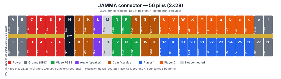
The connector
- 56-pin card edge (28 per side), 3.96 mm (.156″) pitch.
- Solder side labelled with letters (A, B, C… skipping G, I, O, Q to avoid confusion), parts side with numbers (1 to 28).
- Key: position 7 (H/7) is blocked (pin cut on the board, slot plugged on the connector) → prevents reversed insertion.
- Crimped (IDC) or solder-type female connector on the cabinet harness.
Complete pinout
| Pos | Solder side (letter) | Parts side (nº) |
|---|---|---|
| 1 | GND (A) | GND (1) |
| 2 | GND (B) | GND (2) |
| 3 | +5 V (C) | +5 V (3) |
| 4 | +5 V (D) | +5 V (4) |
| 5 | −5 V (E) | −5 V (5) |
| 6 | +12 V (F) | +12 V (6) |
| 7 | KEY (H) | KEY (7) |
| 8 | Coin counter 2 (J) | Coin counter 1 (8) |
| 9 | Coin lockout 2 (K) | Coin lockout 1 (9) |
| 10 | Speaker − (L) | Speaker + (10) |
| 11 | N.C. (often audio GND) (M) | N.C. (11) |
| 12 | Video Green (N) | Video Red (12) |
| 13 | Video Sync (P) | Video Blue (13) |
| 14 | Service (R) | Video GND (14) |
| 15 | Test (S) | Tilt (15) |
| 16 | Coin 2 (T) | Coin 1 (16) |
| 17 | Start 2 (U) | Start 1 (17) |
| 18 | P2 Up (V) | P1 Up (18) |
| 19 | P2 Down (W) | P1 Down (19) |
| 20 | P2 Left (X) | P1 Left (20) |
| 21 | P2 Right (Y) | P1 Right (21) |
| 22 | P2 Button 1 (Z) | P1 Button 1 (22) |
| 23 | P2 Button 2 (a) | P1 Button 2 (23) |
| 24 | P2 Button 3 (b) | P1 Button 3 (24) |
| 25 | P2 Button 4* (c) | P1 Button 4* (25) |
| 26 | P2 Button 5* (d) | P1 Button 5* (26) |
| 27 | GND (e) | GND (27) |
| 28 | GND (f) | GND (28) |
Pins 25 / 26 (c / d) — outside the original standard
Original JAMMA defines only 3 buttons per player; pins 25 and 26 were N.C.. By de-facto convention pin 25 became button 4 (used by the Neo-Geo MVS, JAMMA-compatible pinout), and 6-button boards (CPS, etc.) add buttons 4/5/6 outside JAMMA via a separate "kick harness" (see below). Always check the board's own documentation.
Signal groups
| Group | Pins | Notes |
|---|---|---|
| Power | +5 V (×2), +12 V, −5 V | +5 V logic (most critical); −5 V rarely used (some audio) |
| Ground (GND) | 1,2,27,28 (+ M audio) | several GND pins in parallel → wire them all (+5 V current) |
| RGBS video | Red, Green, Blue, Sync, GND | analog ~0.7 Vpp, negative composite sync (TTL), 15 kHz |
| Audio | Speaker + / − | mono amp output (a few watts) → 4–8 Ω speaker. Stereo runs outside JAMMA. |
| Coin / service | Coin 1/2, counter, lockout, service, test, tilt | active-low inputs (contact to GND) |
| Controls | 4-way joystick + buttons, ×2 players | active-low: button wired between the pin and GND |
Wiring points to know
- Active-low contacts: each button/direction ties its JAMMA pin to GND. The panel's ground daisy-chain starts from a JAMMA GND pin (see Control panels & buttons).
- Adjust +5 V under load: aim for +5.0 V measured at the JAMMA edge (not at the PSU). Voltage drop = crashes, corrupted sprites. Adjust on the candy cab PSU.
- Sync: negative composite in the JAMMA standard; some monitors want separate sync or sync-on-green → adapter.
- Stereo & buttons 4/5/6: do not run through the 56-pin JAMMA → extra connectors (Capcom kick harness, Sega candy audio harness). See the specific cabinet.
- JAMMA "suicide": on protected boards (FD1094…), JAMMA also feeds the battery — see the PCB pages (desuicide).
The "kick harness" (buttons 4/5/6)
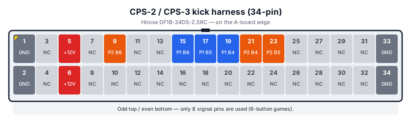
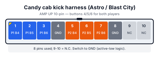
6-button games (Street Fighter II, CPS) add a second connector (often a 6/10-pin Kick connector at the board edge) carrying buttons 4/5/6 for each player + GND. Same wiring (contact to GND), but outside the JAMMA harness.
The format depends on the maker. Two very common cases:
Capcom CPS-2 / CPS-3 — a 34-pin Hirose DF1B-34DS-2.5RC connector on the A-board edge (only 8 pins carry a signal; the rest are N.C. or reserved for players 3/4):
Sega candy cab (Astro / Blast City) — an AMP UP 10-pin harness dedicated to buttons 4/5/6 of both players:
→ see CPS conversions, the Astro City cabinet and the host cabinet.
JAMMA vs JVS
JAMMA carries everything in parallel on a card edge; JVS (Naomi era on) splits game and I/O: controls over serial (RS-485) via a JVS I/O board, power and video separately. Many modern cabinets are JVS, or JAMMA + JVS (late tri-sync candy cabs).
→ Repair: PCB fault-finding · CRT safety (monitor) · Recap.
Sources & attribution
- JAMMA standard — 56-pin pinout (Museum of the Game / Arcade Repair Tips / Arcade Otaku) — https://wiki.arcadeotaku.com/w/JAMMA
- Arcade Repair Tips — JAMMA Connector Pinout Sheet — https://www.arcaderepairtips.com/jamma.html
- Internal pages: JVS · Control panels · candy cab PSU
Review & corrections
How this space is used
Spotted a wrong value, an outdated procedure, a chip reference that does not match your board? Say so here, with what you observed (model, board revision, serial number, measurement). Every report is cross-checked against a source before anything changes — an unverifiable correction is published as “reported by …, not cross-checked” rather than silently applied.
Reading is open to everyone; posting requires signing in with Discord. Reports from the wiki's declared reviewers are handled first; anyone else's are read too, but go through a human before anything is changed.