Atari Jaguar
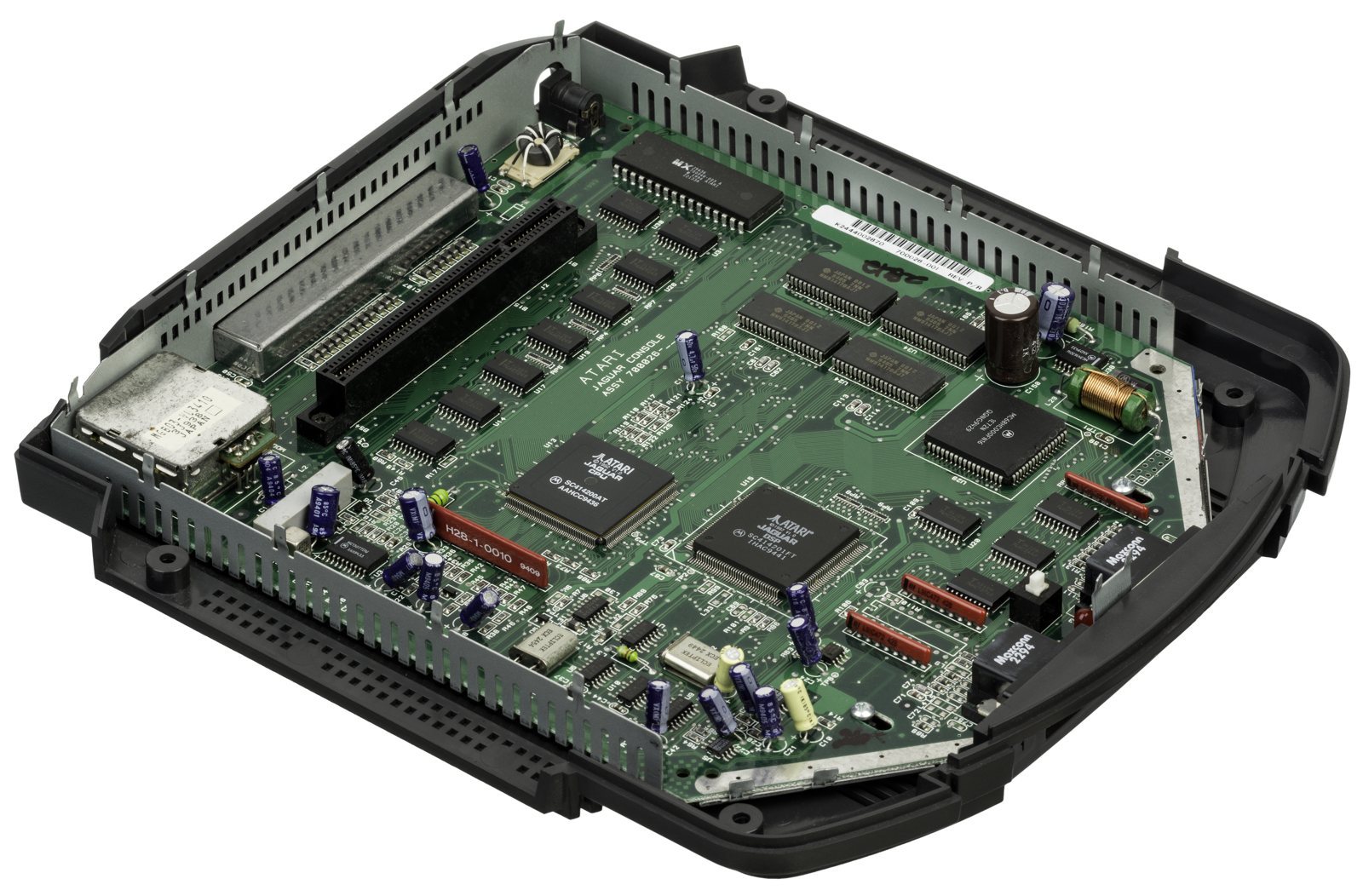
Atari's last console (1993), sold as "64-bit". A complex multi-processor architecture (68000 + Tom & Jerry customs), cartridge-based (+ Jaguar CD add-on). A commercial failure, but a cult one. Native RGB.
Identification
| Field | Value |
|---|---|
| Manufacturer | Atari |
| Release | 1993 |
| Generation | 5th |
| Native video output | RGB (+ composite/S-Video) |
| Media | Cartridge (+ Jaguar CD) |
Architecture
| Block | Chip | Clock | Role |
|---|---|---|---|
| "Manager" | Motorola 68000 | ~13.3 MHz | meant as a mere conductor… often used as the main CPU (a perf mistake) |
| Tom | custom ASIC (26.6 MHz) | Object Processor + Blitter + RISC GPU — the real graphics engine | |
| Jerry | custom ASIC (26.6 MHz) | audio DSP (synthesis) + I/O + timers | |
| Memory | 2 MB DRAM (64-bit bus) | ||
| Media | Cartridge (+ Jaguar CD add-on) |
The "64-bit" marketing = a 64-bit memory bus. Reputedly very hard to program: the power is in Tom/Jerry, but many studios leaned on the (slow) 68000, hence disappointing games.
Jaguar CD, Memory Track & controller
- Jaguar CD (1995): a double-speed add-on sitting on the cartridge slot, notoriously unreliable (the infamous "red screen of death" at boot). Few games; a collector's item.
- Memory Track: a save cartridge (non-volatile memory) for CD games, which have no other save medium.
- Controller: 3 action buttons + a 12-key numeric keypad covered with per-game cardboard overlays (Atari design heritage). The ProController adds 6 buttons.
Cartridge slot / loading
The cartridge port accepts a flashcart (e.g. a "Jaguar SD") to load the library and homebrew — the Jaguar scene has stayed active.
Common faults
| Symptom | Likely cause | Lead |
|---|---|---|
| Cartridge not read | Contacts | Cleaning |
| Jaguar CD won't read | Laser / add-on | Repair / ODE |
| No image | Power, contacts, customs | Diagnosis |
| Regulator, 2 caps and 1 resistor burnt out | Wrong mains brick — no protection from the factory | Repair, then fit the 1N5400 diode |
| Will not power up after fitting the diode | Diode fitted the wrong way round | Reverse it (see the box) |
| Intermittent contacts / in-game crashes | Cartridge port pins (fragile on the Jaguar) | Cleaning, inspect the pins |
(Recap secondary depending on age.)
Procedure — a dead console, step by step ✅
What this adds
Ordered for a console, not for an arcade board: what kills these is almost never the CPU. It is, in real order, the power supply, the capacitors, the drive or the cartridge slot, and only then the logic. → PCB diagnosis
1. The power supply. Two cases, depending on the machine. External brick: ⚠️ read the marking on the machine, next to the socket, and check the adapter against it — voltage and polarity. A centre-negative machine fed centre-positive loses its fuse, sometimes its regulator; do not trust a third-party label or a generic tip. Internal supply (the machine plugs straight into the wall): mains is inside the shell. Unplug, wait, and confirm the large capacitors are discharged before touching the board. Either way, measure under load: a failing supply holds its voltage until it is asked for current.
2. The fuse. Many of these machines have one right behind the socket — it is the part designed to die. Test it in continuity, out of circuit. A fuse that blows again is a short, not a fuse problem.
3. Capacitors. On most machines of this age this is the default suspect rather than a last resort — leaking SMD electrolytics eat the tracks underneath before they give any other sign. ⚠️ Not all of them are like that: some carry very few and are not recapped on principle. Read what this page says about it before reaching for the iron. → Recap
4. The cartridge connector. Cartridge contacts with isopropyl alcohol, never an abrasive eraser: it takes the gold plating off and the problem comes back worse. On the machine side, inspect the slot pins — splayed, bent or oxidised — and check continuity between slot and board.
5. Video output. Isolate the machine from the display: another cable, another TV, another input. A sizeable share of "dead consoles" are a dead cable, or a display that will not lock onto what this machine outputs — see the video section of this page for what that is.
6. Still nothing. Now, and only now, the logic: rails on the board, reset, clock, bus. → PCB diagnosis
Revisions — K series or M series ✅
There is only one Jaguar model, but two revisions, readable directly from the serial number.
| Revision | Tell | What characterises it |
|---|---|---|
| K series (1993 → 1993/94 or 1995) | Serial number beginning with K | Early units have some faults in the chips and build, but have an ADC in the controller ports — which allows analogue controllers to be used. ⚠️ Some K systems were produced later, eliminating the faults but also the analogue support. |
| M series (1993/94 → 1996) | Serial number beginning with M | Defined mostly by what it doesn't have: neither the K's chip faults, nor the ADC ports. |
A common claim, explicitly unverified
It is often said that K series consoles work better with the Jaguar CD (a notoriously difficult add-on). The source flags this as unsubstantiated and in need of verification — we report it as such rather than presenting it as fact.
Hardware points worth knowing
The famous "toilet seat" shape, top-loading cartridge slot with easily broken cartridge pins, native RGB out at the back, and a "DSP" port — the one used by the JagLink network adapter, which apparently follows typical RS-232 conventions.
Reverse polarity protection — the preventive mod ✅
Neither the Jaguar nor the Jaguar CD has reverse polarity protection
Plugging in the wrong power supply fries the power regulator, two capacitors and a resistor. If you are servicing a Jaguar, this is the mod to do while you are in there: it is quick and purely preventive. (Source: ConsoleMods, CC-BY-SA.)
Part: a 1N5400 rectifier diode (protection up to 3 A). A higher voltage rated diode also works.
- Desolder the wire connecting a ferrite filter to the positive pin on the side of the power supply terminal. ⚠️ The wire colour varies between revisions — it may be black, red or white. Go by the location, never the colour (see the photo on the source page).
- Solder the diode to the now-empty trace where the filter wire was connected. The bar (or line) denoting the cathode (negative) side should face up; the anode (positive) side is soldered to the PCB.
- Solder the filter wire to the cathode side of the diode — the one with the bar.
- Clean any remaining flux with isopropyl alcohol.
- Locate C74 and C75, beside the power supply jack.
- With a razor, carefully cut the trace between C74 and the pad beside it. You don't need a big gash: two clean, thin lines perpendicular to the trace are enough to sever it.
- Confirm with a multimeter that there is no longer continuity between C74 and that pad.
- Solder the diode: cathode side (bar) to the pad, anode side to C75.
- Clean any remaining flux with isopropyl alcohol.
The test that confirms orientation
If the diode is soldered backwards, the console simply won't power on. That is the symptom to know: no mysterious fault, just a direction to reverse.
Region / 50-60 Hz ✅
The NTSC and PAL Jaguar motherboards are nearly identical: they differ only by the clock crystal and two jumpers set differently.
| Item | State | Effect |
|---|---|---|
| R140 | 0 Ω resistor in place | The system runs at 50 Hz instead of 60 Hz |
| R19 | 0 Ω resistor NOT in place | The video encoder outputs PAL over RF, composite and S-Video |
| Crystal Y1 | 14.3 MHz (NTSC) → 17.7 MHz (PAL) | The 17.7 MHz provides PAL's 4.43 MHz colour carrier frequency |
Going to 60 Hz — remove jumper R140: it is on the bottom side of the motherboard, near controller port 2, possibly marked "R140". Heat each side, add fresh solder and remove the resistor. Tip: leaving it attached by one pad lets you undo the mod at any time. Switchable variant: fit an SPST switch and solder a wire between each leg and the pads, to toggle 50/60 Hz.
Setting the video encoder to NTSC colour — populate R19: the pad is on the top side of the board, near the cartridge slot, possibly marked "R19". Solder a 0 Ω resistor onto it.
The crystal governs the final result
If the Y1 crystal is not replaced, populating R19 yields NTSC4.43 (NTSC colour with a 4.43 MHz colour carrier) and not PAL60. Worth knowing before judging the result on a display.
What the source does not say (and we do not invent)
The ConsoleMods page leaves two explicit gaps: the exact SMD size of the R19 0 Ω resistor is an unfilled placeholder, and the Y1 crystal replacement section is an empty "TODO" (no modern compatible crystal is identified). We fill in neither: measure the footprint on your own board for R19, and source the crystal from the community.
Popular mods — what to buy, how
- Native RGB: the Jaguar already outputs RGB on its DB15 AV connector → just an RGB/SCART cable (or into an OSSC/RetroTINK) — no internal mod needed 🟢. Excellent stock picture.
- Flashcart: the Jaguar GameDrive (RetroHQ) — games/homebrew on SD, plug-and-play 🟢. For the Jaguar CD (rare, fragile lens), a community ODE preserves the CD side.
- Reliability: preventive recap + clean cartridge contacts (bad seating = crashes) and the expansion connector. The Jaguar CD often needs a laser clean/adjust.
Photos / assets
(To add: console, board, Jaguar CD.)
Advanced repair
Recap + cartridge/CD contacts; the (rare) Jaguar CD = laser/optics. Methods: Recap · PCB fault-finding · Traces & vias.
Archived manufacturer documentation ✅
Manufacturer documentation archived locally. ⚠️ These are owner's and reference manuals, not service manuals: they give the specifications, the connectors and the expected behaviour, but not the schematics or troubleshooting voltages.
- Jaguar — PDF
Status
Manufacturer documents with no explicit licence, kept for preservation (machines out of production for decades).
Sources & attribution
- Wikipedia — Atari Jaguar — CC-BY-SA — https://en.wikipedia.org/wiki/Atari_Jaguar
- ConsoleMods Wiki — Jaguar Model Differences — CC-BY-SA — K and M series, controller port ADC, DSP/JagLink port — in collaboration with io55.net — https://consolemods.org/wiki/Jaguar:Jaguar_Model_Differences
- ConsoleMods Wiki — Reverse Polarity Protection Diode — CC-BY-SA — no factory protection, 1N5400 diode, console and Jaguar CD procedures (C74/C75) — https://consolemods.org/wiki/Jaguar:Reverse_Polarity_Protection_Diode
- ConsoleMods Wiki — 50/60hz Switch — CC-BY-SA — R140 and R19 jumpers, Y1 crystal 14.3 vs 17.7 MHz, the NTSC4.43 trap — https://consolemods.org/wiki/Jaguar:50/60hz_Switch
Image:
-
jaguar-board.jpg— Evan-Amos, public domain — https://commons.wikimedia.org/wiki/File:Atari-Jaguar-Motherboard-R.jpg

Review & corrections
How this space is used
Spotted a wrong value, an outdated procedure, a chip reference that does not match your board? Say so here, with what you observed (model, board revision, serial number, measurement). Every report is cross-checked against a source before anything changes — an unverifiable correction is published as “reported by …, not cross-checked” rather than silently applied.
Reading is open to everyone; posting requires signing in with Discord. Reports from the wiki's declared reviewers are handled first; anyone else's are read too, but go through a human before anything is changed.