Sega G80 (raster & vector)
Sega's flexible early-80s platform (1981), in two versions: raster (Astro Blaster, 005, Monster Bash) and vector (Space Fury, Star Trek, Eliminator, Tac/Scan, Zektor). The vector side shares the constraints of Atari's vector cabinets: an XY monitor and high voltage.
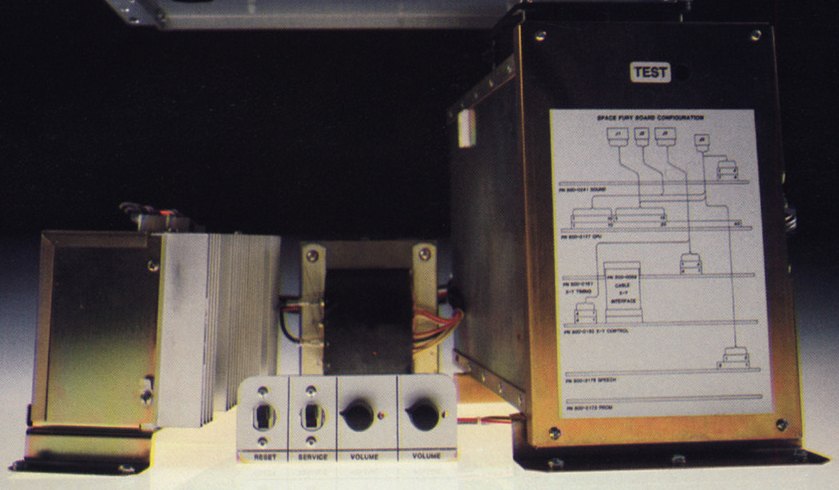
Identification
| Field | Value |
|---|---|
| Manufacturer | Sega / Gremlin |
| Years | 1981-1983 |
| Versions | G80 raster · G80 vector |
| CPU | Zilog Z80 |
| Sound | dedicated sound boards + speech synthesis depending on the game |
Architecture
| Block | Chip | Role |
|---|---|---|
| CPU | Zilog Z80 | game logic |
| Video (raster) | tiles + sprites | Astro Blaster, 005, Space Odyssey, Monster Bash, Pig Newton |
| Video (vector) | vector generator + XY monitor | Space Fury, Zektor, Tac/Scan, Eliminator, Star Trek: SOS |
| Sound | Universal Sound Board + per-game speech/sound boards | music/SFX + synthesized speech (Space Fury, Star Trek…) |
⚠️ Zaxxon is NOT a G80 game: despite Sega's "Convert-a-Game" promise, the big hits Zaxxon and Pengo shipped on bespoke hardware — Zaxxon's success actually undermined the G80 concept. The last G80 came in 1983.
The vector side (specific repair)
Vector G80s use an XY monitor (often Electrohome G08), with the same dangers as the Atari vector:
- CRT high voltage → discharge before working on it.
- Fixed bright dot = phosphor burn risk → cut power immediately.
- Repair = recap + reflow of the deflection, vector-generator diagnosis.
Notable games
- Raster: Astro Blaster (1981), 005, Space Odyssey, Monster Bash.
- Vector: Space Fury (1981), Zektor, Tac/Scan, Eliminator, Star Trek: Strategic Operations Simulator (1982, the most famous).
The Sega/Gremlin Service Notes ✅
⚠️ Three G-80 notes, two of them modifications that may be missing from your machine
The G-80 system Service Notes (Sega Electronics, Inc., 16250 Technology Drive, San Diego) each carry a priority ticked at the head — Urgent, Upon Game Failure, For Information Only. ⓘ That is the first thing to read: it says whether the note is an obligation or a conditional remedy.
ⓘ They apply to the whole G-80 range, which note no. 001 lists as of 16 March 1983: Astro Blaster, Space Odyssey, Space Fury, Eliminator, Four-Player Eliminator, 005, Zektor, Tac/Scan, Monster Bash, Star Trek.
CPU note no. 001 — spurious resets ("Upon Game Failure")
⚠️ "In the advent that you are experiencing CPU Reset difficulties with any of your G-80 games […] we recommend that you replace the existing .22 µF capacitor C45 on the CPU Board Assembly (Drawing No. 800-0107), with a 1.0 µF 25 V capacitor (P/N 150-0135-00)".
ⓘ And the note corrects the schematic itself: "correct the stated schematic value (to 1.0 µF 25 V), and revise the corresponding parts list". ⚠️ A period schematic showing 0.22 µF is therefore not a reference — it is the pre-correction value.
Power supply note no. 001 — a factory modification that may be missing
⚠️ "It has been noted that an 'in-house' modification of the G-80 Power Supply (P/N 800-0191) may not have been accomplished on all units in the field" — it distributes the ground current return to an additional connector pin.
✅ It is checked in a minute, with the rear electronics door open: remove the two screws from the power supply cover, then inspect P4 pin 4 to see whether it is tied to ground, "either by a solder-bridge or jumper-wire to pin-6 of the same plug". If not, expose the land next to P4 pin 4 and solder to the top of the board (P/N 800-0170), or solder a 14 AWG minimum wire between pins 4 and 6 of P4.
Power supply note no. 003 — ⚠️ Urgent, take the coin-mech lamps off the +5 V
⚠️ On G-80 power-supply games fitted with lighted coin mechs, the modification "is designed to relieve the +5 VDC supply of the load from the coin mech. lights":
- with the electronics door open, find the input connector P5, at the rear left of the G-80 card cage;
- remove it, windows facing you, pin 1 (orange wire) up; find the brown wire on pin 8 (from P12) and cut it as close to the connector as possible;
- find the violet wire on pin 7 of P5; cut it an inch and a half to two inches back from the connector, and strip 3/8″ to 1/2″ from all three ends;
- twist the three together, and secure with an insulated blind-crimp or a wirenut;
- plug P5 back in, then correct the wiring diagram and change the power harness part number to 800-0482-02.
Which cabinet, which coin mech, which monitor — the Sega/Gremlin cross-reference ✅
The general technical notices hold a table giving, for each game and each cabinet variant, the part numbers of the cabinet, coin system, cash box, monitor and manual.
⚠️ It first shows that the monitor changes with the cabinet, for the same game:
| Game | Cabinet | Monitor |
|---|---|---|
| Space Fury | Upright | 200-0025-00 |
| Space Fury | Cocktail | ⚠️ 200-0053-00 |
| 005 | Upright | 200-0022-00 |
| 005 | Cocktail | ⚠️ 200-0039-00 |
| Star Trek | Upright and Cockpit | 200-0025-00 — ⓘ the same here |
| Subroc-3D | Upright and Cockpit | 200-0039-00 |
⚠️ And above all, it shows Sega did not fix one monitor per game. Several entries point to footnotes:
- (5) — Zaxxon Upright, Monster Bash Upright, Pengo Upright, Super Zaxxon Upright, Buck Rogers Upright, Congo Bongo Upright: ⚠️ "Uses either assembly, 200-0019-00, 200-0022-00 or 200-0091-00" — three possible monitors for the same slot;
- (4) — Turbo Mini: "either 200-0013-00, 200-0046-00 or 200-0075-00";
- (3) — Turbo Upright: ⓘ "200-0052-00 for 16″ assembly or 200-0039-00 for 20″ assembly" — here it is tube size that decides;
- (6) — cash boxes: "220-0297-00 for COINCO assemblies and 220-0303-00 for WICO assemblies";
- (1) — 4-player Eliminator: "Uses both assemblies, 800-0339-00 and 800-0340-00";
- (2) — several uprights: "either 220-0194-00 or 220-0195-00".
ⓘ So "which monitor should be in my cabinet?" does not always have a single answer, and it is the manufacturer saying so. → Sega G80 · Monitors
⚠️ This wiki reproduces the table as printed, footnotes included. Three manual cells are empty in the original (005 Cocktail, Monster Bash Cocktail, Congo Bongo Cocktail) — they are not filled in here.
Common faults
| Symptom | Likely cause | Lead |
|---|---|---|
| Distorted/missing lines (vector) | XY deflection / joints | Reflow, deflection diagnosis |
| Dead screen, HV ok (vector) | vector generator / caps | Recap + diagnosis |
| No speech (SFX ok) | speech board | Speech-board diagnosis |
| Corrupt raster image | video RAM, Z80 | RAM test, contacts |
| No image | Power, Z80, harness | Base diagnosis |
Modernisation & mods
The common ground for every JAMMA board
Video, power, control panel and upscalers depend on the cabinet rather than the board: everything is centralised in Modernising a cabinet. To run the board outside a cabinet (at home, on a display): supergun.
- Storage 🟡: the game lives in EPROM/mask ROM on the board. Changing or restoring a game means reprogramming the EPROMs (and, for a mask ROM, using a pinout adapter) → EPROM method.
- Media preservation: replacing the original storage, multicarts, ODEs and modern options by family → PCB preservation hub.
- Scan rate 📺: ~15.72 kHz / 60.0 Hz (raster versions) — standard resolution, a classic 15 kHz chassis is fine → tri-sync and upscalers.
(Computed from the MAME sources —
sega/segag80r.cpp— pixel clock ÷ htotal.) - FPGA / emulation: see the Emulation & FPGA section below.
Repair (technician)
- Sega 315-xxxx encryption (address/data) on many games: without the correct decode board/chip the game won't run — check before suspecting the logic.
- Vector side: a high-voltage XY monitor → CRT safety.
- Speech: a separate voice synthesis board — silent voice ≠ a main-sound fault.
- Discrete Z80 logic: TTL/RAM/buffer diagnosis; 2716/2732 EPROMs on sockets (oxidised legs → turned-pin socket).
→ Methods: PCB fault-finding · Recap · EPROM · Traces & vias
Expected clocks — measurement table ✅
Values extracted from the MAME sources for this platform. On a scope or frequency counter, a clock that is missing or off-value points straight at the crystal, the divider or the chip at fault — the fastest starting point on a dead board.
| Component | Expected clock | Role |
|---|---|---|
| Z80 | 3.86712 MHz · 4 MHz | sound CPU (usually) |
How to read this table
Several values for one component = several board variants in this family (or several instances of the chip clocked differently). These frequencies are those of the clock signal at the component's input, not of its original crystal — on many boards the clock is divided down from a single master crystal.
Archived original schematics ✅
Manufacturer schematics for games in this family, archived locally. They give the clock tree, the address decoding and the breakdown of the video/sound/power stages — enough to trace a missing signal back to its source.
- Highway (TM-028) — full schematic (PDF)
- Monster Bash — full schematic (PDF)
- Tranquilizer Gun — full schematic (PDF)
Scope
A schematic applies to the game and revision named: within a family the general breakdown carries over, but component references and custom chip pinouts do not transpose. Source: the Arcade Game Manuals collection (Internet Archive), manufacturer documents kept for preservation.
Manufacturer service bulletins ✅
Fixes the manufacturer issued to its network: they document a factory-acknowledged fault, its symptom and the modification to apply.
→ Full catalogue: service manuals & wiring diagrams
DIP settings ✅
8 games on this platform, settings extracted from the MAME sources (INPUT_PORTS_START blocks). The Position column gives the switch's physical reference on the board (SW2:!3,!4 = bank SW2, levers 3 and 4) — which is what lets you set it up without the paper manual. Games are sorted by MAME set name.
DIP settings — MAME set 005
| Setting | Position | Options (default in bold) |
|---|---|---|
| Lives | SW1:8,7 | 3 · 4 · 5 · 6 |
| Cabinet | SW1:6 | Upright · Cocktail |
DIP settings — MAME set astrob
| Setting | Position | Options (default in bold) |
|---|---|---|
| Lives | SW1:8,7 | 2 · 3 · 4 · 5 |
| Cabinet | SW1:6 | Upright · Cocktail |
| Demo Speech | SW1:5 | Off · On |
DIP settings — MAME set astrob2
| Setting | Position | Options (default in bold) |
|---|---|---|
| Lives | SW1:8,7 | 2 · 3 |
DIP settings — MAME set g80r_generic
| Setting | Position | Options (default in bold) |
|---|---|---|
| Coin A | SW2:8,7,6,5 | 4C 1C · 3C 1C · 2C 1C · 2 Coins/1 Credit 5/3 6/4 · 2 Coins/1 Credit 4/3 · 1C 1C · 1 Coin/1 Credit 5/6 · 1 Coin/1 Credit 4/5 · 1 Coin/1 Credit 2/3 · 1C 2C … |
| Coin B | SW2:4,3,2,1 | 4C 1C · 3C 1C · 2C 1C · 2 Coins/1 Credit 5/3 6/4 · 2 Coins/1 Credit 4/3 · 1C 1C · 1 Coin/1 Credit 5/6 · 1 Coin/1 Credit 4/5 · 1 Coin/1 Credit 2/3 · 1C 2C … |
DIP settings — MAME set monsterb
| Setting | Position | Options (default in bold) |
|---|---|---|
| Lives | SW1:8,7 | 3 · 4 · 5 · 6 |
| Cabinet | SW1:6 | Upright · Cocktail |
| Difficulty | SW1:5,4 | Easy · Medium · Hard · Hardest |
| Bonus Life | SW1:3,2 | 10000 · 20000 · 40000 · None |
| Infinite Lives (Cheat) | SW1:1 | Off · On |
DIP settings — MAME set pignewt
| Setting | Position | Options (default in bold) |
|---|---|---|
| Cabinet | SW1:8 | Upright · Cocktail |
| Demo Sounds | SW1:7 | Off · On |
| Lives | SW1:6,5 | 3 · 4 · 5 · 6 |
DIP settings — MAME set sindbadm
| Setting | Position | Options (default in bold) |
|---|---|---|
| Lives | SW1:8,7 | 3 · 4 · 5 · 6 |
| Cabinet | SW1:6 | Upright · Cocktail |
| Infinite Lives (Cheat) | SW1:1 | Off · On |
| Coin A | SW2:8,7,6,5 | 4C 1C · 3C 1C · 2C 1C · 2 Coins/1 Credit 5/3 · 2 Coins/1 Credit 4/3 · 1C 1C · 1 Coin/1 Credit 5/6 · 1 Coin/1 Credit 4/5 · 1 Coin/1 Credit 2/3 · 2C 3C … |
| Coin B | SW2:4,3,2,1 | 4C 1C · 3C 1C · 2C 1C · 2 Coins/1 Credit 5/3 · 2 Coins/1 Credit 4/3 · 1C 1C · 1 Coin/1 Credit 5/6 · 1 Coin/1 Credit 4/5 · 1 Coin/1 Credit 2/3 · 2C 3C … |
DIP settings — MAME set spaceod
| Setting | Position | Options (default in bold) |
|---|---|---|
| Lives | SW1:8,7 | 3 · 4 · 5 · 6 |
| Cabinet | SW1:6 | Upright · Cocktail |
| Bonus Life | SW1:5,4 | 20000 · 40000 · 60000 · 80000 |
| Infinite Lives (Cheat) | SW1:1 | Off · On |
Check against your own board
These settings apply to the game and revision described by MAME. One title may have several DIP sets depending on region or revision, and some systems use soft-dips (settings in memory, via the test menu) rather than physical switches. In case of a discrepancy, the board's silkscreen and the test menu are authoritative.
See also: DIP reference · game manuals
Procedure — a dead board, step by step ✅
What this adds
The general method lives in PCB diagnosis. This is its application to this platform: the same order, but with the values actually expected here, so you do not have to go back and forth.
Tools: multimeter, oscilloscope (or frequency counter), current-limited bench supply, desoldering braid. → Tooling
If the board is still in a cabinet
A CRT holds its charge with the machine unplugged. → CRT safety
1. Inspection, power off. Corrosion, cut tracks, oxidised EPROM legs, leaking SMD capacitors, dubious earlier repairs.
2. The connector, before anything else. A large share of "dead boards" are a contact problem, not a fault. Clean the contacts with isopropyl alcohol and reseat — not with an abrasive eraser on a gold edge, which takes the plating off and brings the problem back worse. It costs two minutes and settles the question.
3. Power, measured on the board. Aim for +5.0 V measured as close as possible to where power reaches the board — not at the PSU output: the drop is in the loom, and that is exactly what makes a board boot on the bench and not in the cabinet. Where you probe depends on this board's connector — JAMMA edge, JVS loom or a proprietary harness — plenty of makers kept one long after JAMMA arrived — see Identification above. → Wiring Check −5 V and +12 V too if the sound stage uses them. Suspected short: bring it up current-limited and find the hot spot.
4. /RESET. It must release after power-up. Held low = the CPU never starts. A 1–2 Hz loop is not the reset circuit, it is the watchdog: the CPU is crashing at boot, so look at the bus, not at the reset.
5. Clocks — the values expected on this platform.
- Z80 → 3.86712 MHz · 4 MHz (Sound CPU (usually))
Several values for one component means several board variants in this family, not several readings on the same one: identify yours before calling a clock wrong. That is the mistake that replaces a healthy crystal.
6. Bus. Activity on the main CPU's address lines tells you whether it is running or frozen. Frozen with good clocks and good reset → work RAM, bus buffers, ROMs.
7. It boots but the picture or the sound is wrong — that is another job: see Common faults on this page, then signal tracing.
Emulation & FPGA
- Emulation: MAME (
sega/segag80r.cpp,sega/segag80v.cpp). - FPGA / MiSTer: no confirmed dedicated G80 core → MAME.
EPROM repair
Z80 program: raster (Zaxxon, Congo Bongo) / vector (Space Fury, Star Trek, Tac/Scan). 2716 / 2732 EPROMs. ⚠ Many use a Sega address/data encryption (315-xxxx) → decode board required.
Lineage
Contemporary with Sega arcade's beginnings; precedes the System 1 (1983). Vector kinship with the Atari vector.
Photos / assets
(To add: G80 card cage, vector generator, Electrohome G08 XY monitor.)
Sources & attribution
- Sega Retro — Sega G80 (raster + vector, Z80, games, sound/speech boards) — https://www.segaretro.org/Sega_G80
- System16 — Sega G80 Vector Hardware — https://www.system16.com/hardware.php?id=686
- MAME —
sega/segag80r.cpp&sega/segag80v.cpp— https://github.com/mamedev/mame
Image:
-
g80-cage.jpg— uploaded by Black Squirrel to Sega Retro (site CC BY 4.0; ⚠️ the file carries no individual licence) — https://segaretro.org/File:G80_Arcade.jpg

Review & corrections
How this space is used
Spotted a wrong value, an outdated procedure, a chip reference that does not match your board? Say so here, with what you observed (model, board revision, serial number, measurement). Every report is cross-checked against a source before anything changes — an unverifiable correction is published as “reported by …, not cross-checked” rather than silently applied.
Reading is open to everyone; posting requires signing in with Discord. Reports from the wiki's declared reviewers are handled first; anyone else's are read too, but go through a human before anything is changed.