Sega Mega Drive / Genesis
Sega's 16-bit console (1988). Mega Drive in Japan, Europe and most of the world; Genesis in North America. Native RGB output, a cult FM sound chip, and many hardware revisions that change the sound and video.
Status: under construction
The capacitor values and precise locations will come from a verified source (ConsoleMods, CC-BY-SA) — nothing is invented here.
Summary of linked pages
- Mega Drive Model 2 recap (section below, to extract into a dedicated page)
- Add-ons — one page per module, same structure:
consoles/sega/mega-cd— Mega-CD / Sega CDconsoles/sega/32x— 32X- Power Base / Master System Converter — 8-bit backward-compat
Identification
| Field | Value |
|---|---|
| Manufacturer | Sega |
| Release year | 1988 (JP), 1989 (NA, "Genesis"), 1990 (EU) |
| Generation | 4th (16-bit) |
| Hardware revisions | Model 1: VA0 → VA7; Model 2; Model 3 |
| Native video output | Composite + native RGBs (multi-out); RF on Model 1 |
| Region / lockout | Region lock (cartridge shape + check) + 50/60 Hz |
| Media format | ROM cartridge; Mega-CD, 32X add-ons |
Architecture
| Block | Component | Notes |
|---|---|---|
| Main CPU | Motorola 68000 @ ~7.67 MHz (NTSC) | 16/32-bit core |
| Secondary CPU | Zilog Z80 @ ~3.58 MHz | Sound; Master System backward-compat (via Power Base Converter) |
| Video (VDP) | Sega 315-5313 | 320×224 (NTSC) / 320×240 (PAL); 512 palette, ~61 on screen |
| FM sound | Yamaha YM2612 (early) / integrated YM3438 (Model 2) | 6 FM channels, 1 PCM channel |
| PSG sound | TI SN76489 | Integrated in the VDP; 3 voices + noise |
Revisions & differences (the key collector point)
The sound changes by revision — that's THE big story of the machine.
| Revision | Sound chip | "Ladder effect" | Notes | Status |
|---|---|---|---|---|
| Model 1 VA0–VA3 | discrete YM2612 | Yes ("crunchy" sound) | Loud audio, noisier | to confirm |
| Model 1 VA6/VA6.5/VA7 | ASIC integration | TMSS arrives | ||
| Model 2 | integrated YM3438-type | No | Cleaner, finer sound; SMD caps | |
| Model 3 | integrated | No | No clean RGB, no ext. port | — |
This VAx → chip/sound table must be verified unit by unit (online lists diverge). To be pinned down with a reliable source.
Disassembly (Model 1) — tutorial
Number/type of screws to confirm per revision. No HV here (it's not a CRT), but unplug the power first.
- Flip the console over, remove the bottom screws (Phillips).
- Separate the top shell from the bottom.
- Remove the RF shield (metal cage): unfold the tabs / screws.
- Take the motherboard out of the bottom shell.
- Orientation: locate the PSU/fuse F1, multi-out, YM/PSG, region area.
Disassembly sequence (Model 2 example)
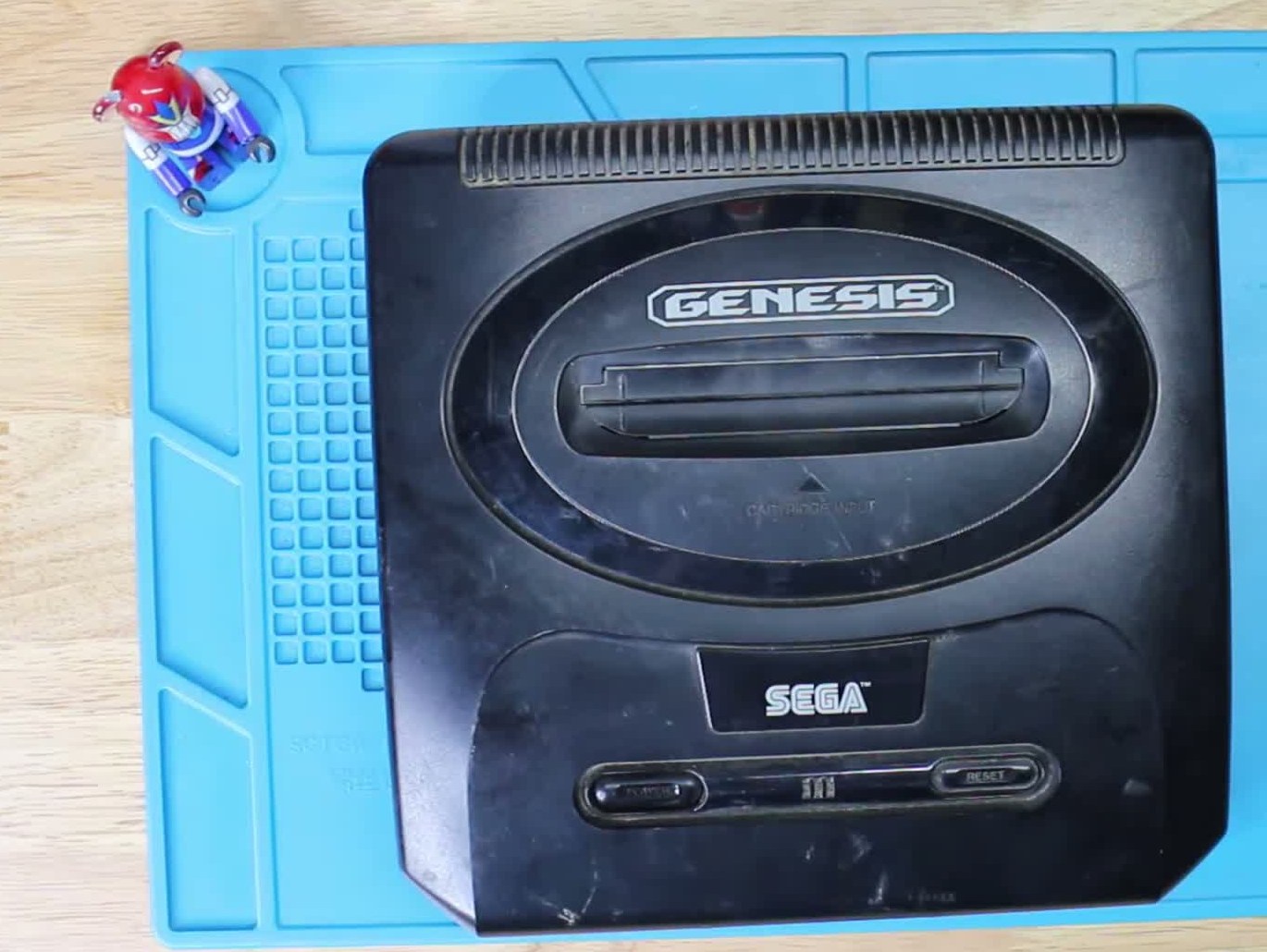
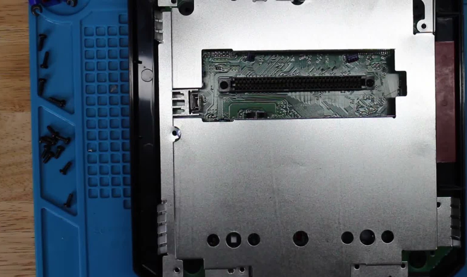
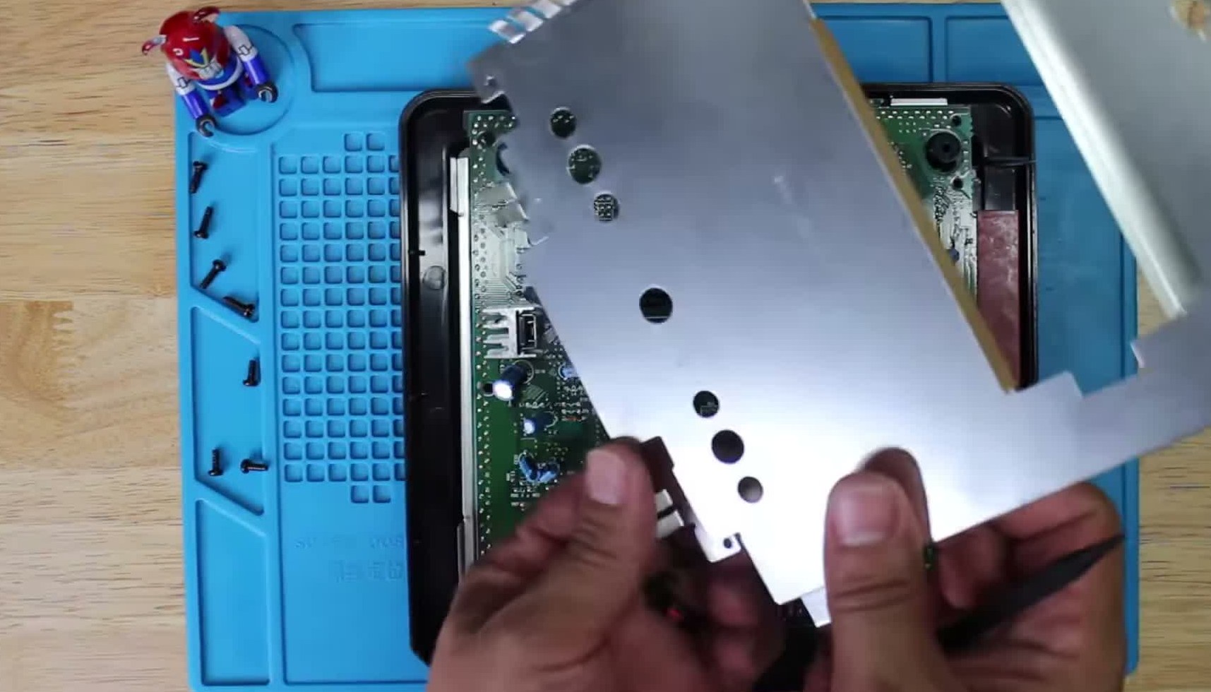
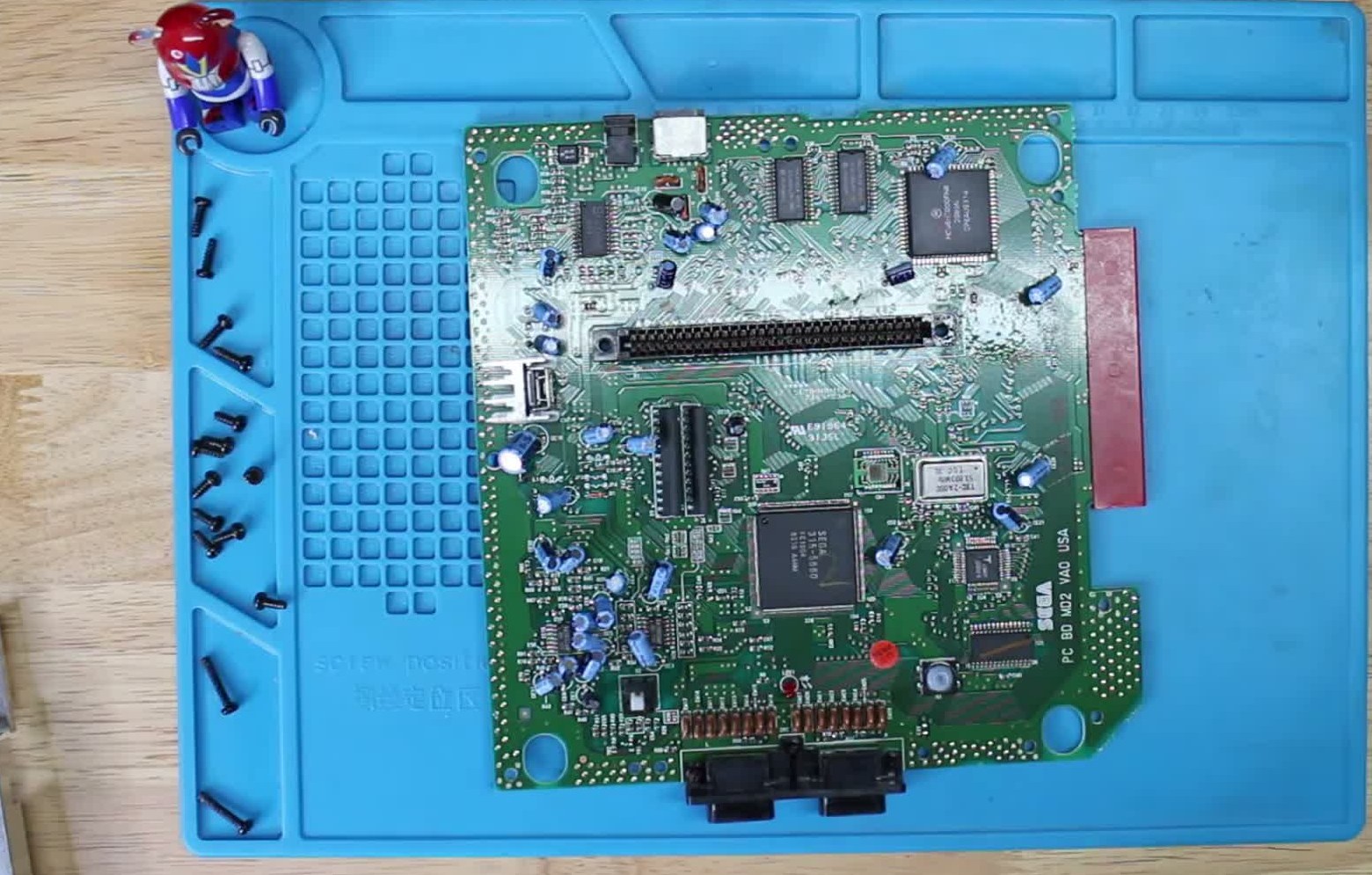
Frames extracted and cropped from the TRU Fixes teardown video (Model 2), CC-BY 3.0.
Model 1 stills — to complete
The sequence above is a Model 2. Model 1 stills are still missing — ideally
your own photos (original heritage), e.g. md1-vis-dessous, md1-carte-verso.
Full video teardown (CC-BY 3.0):
Sega Genesis 2 — Complete Teardown & Cleaning — TRU Fixes.
Once the board is out, with the components identified:
- RF modulator (MIT60M)
- 68000 CPU (HD68HC000P8)
- VDP (SEGA 315-5313A)
- FM sound (Yamaha YM2612)
- Z80 (sound / Master System backward-compat)
- Work RAM (MCM51L832 ×2)
- Crystal 53.203 MHz
- Cartridge slot
- Expansion port (edge connector)
- Controller ports (×2)
- Region jumpers (JP…) — for the region-free mod; this board already has a wired mod (purple/blue/brown wires)
- Switches (SW1 reset / power)
Key component locations
- 68000 CPU (MC68HC000FN8)
- Work RAM (MCM51L832 ×2)
- VDP (SEGA 315-5487)
- VRAM (MB81461 ×2)
- Master crystal 53.693 MHz
- Cartridge slot
- Expansion port (edge connector)
- Controller ports (×2)
- DC power + A/V output
- Regulator (under a heatsink)
- Capacitor area — SMD, targets of the recap (see below)
Common faults
| Symptom | Likely cause | Repair |
|---|---|---|
| Nothing at power-on | Reversed centre-negative PSU → blown fuse F1 | Check/replace F1; use the right PSU |
| Degraded sound/video (Model 2) | Leaking SMD caps | Recap (see below) |
| Cartridge not read / corrupted graphics | Cartridge connector oxidation | Clean with iso alcohol |
| Flaky controller | Worn port / dead series diode or resistor | Replace the component |
| Loss of a sound channel | YM or mixing stage | Probe diagnosis |
Original service manual ✅
Manufacturer manual archived locally. It typically carries the schematics, the block diagram, the expected voltages and waveforms, the parts list and the disassembly procedures — the reference when a symptom matches no known fault.
Status
A manufacturer document with no explicit licence, kept for preservation (machine long out of production). Source: Internet Archive.
Step-by-step disassembly procedures ✅
5 procedures transcribed from the iFixit guides, with difficulty and estimated time.
| Procedure | Difficulty | Time |
|---|---|---|
| How to clean the Sega Genesis game port | Very easy | 5 minutes |
| Sega Genesis Reset Button Repair | Easy | 5 - 10 minutes |
| Sega Genesis Motherboard Replacement | Moderate | 15 - 20 minutes |
| Sega Genesis Outer Case Replacement | Moderate | 10 minutes |
| Sega Genesis Power LED Replacement | Easy | 10 minutes |
How to clean the Sega Genesis game port
- Fold fine grit sand paper over a credit card.
- Rub credit card with sand paper up and down vertically inside the game cartridge port.
- Blow out game cartridge port using a can of compressed air.
- Warning: Do not turn the aerosol can upside down as you spray.
- Rub a Q-tip dipped in rubbing alcohol along the pins of the cartridge slot to remove any remaining debris.
Sega Genesis Reset Button Repair
We all know that the Sega Genesis brought to us many hours of fun, but, as we get older, the reset button gets older too. Today, let's lend a hand to our nice friend and replace its reset button!
- Remove the six screws from the underside of the console with a Phillips #1 screwdriver.
- Flip the Sega Genesis upright.
- Gently lift the top casing.
- Note: the case will be connected to the main board by LED wires.
- Bend out the LED leads into vertical positions.
- Slide the LED wire apparatus off the lead pins.
- Note: observe which color wire corresponds with which length of pin.
- Separate the main board from the outer case.
- Using Philips screwdriver, remove 11 screws securing silver casing.
- Remove silver case.
- Locate reset button on motherboard
- Place three pieces of 1cm x 1cm masking tape over reset button.
Sega Genesis Motherboard Replacement
- Remove the six screws from the underside of the console with a Phillips #1 screwdriver.
- Flip the Sega Genesis upright.
- Gently lift the top casing.
- Note: the case will be connected to the main board by LED wires.
- Bend out the LED leads into vertical positions.
- Slide the LED wire apparatus off the lead pins.
- Note: observe which color wire corresponds with which length of pin.
- Separate the main board from the outer case.
- Remove single black screw from the outside of the bottom cover, using a Philips screwdriver.
- Using a Philips screwdriver, remove 11 screws securing silver casing.
- Remove silver case.
- Remove single golden screw on motherboard using Philips screwdriver.
- Note: Push headphone jack to the side.
- Remove two black screws on the left and right sides of the cartridge slot.
- Remove motherboard.
- Re-install new motherboard.
Sega Genesis Outer Case Replacement
This repair guide will take you through all the steps for removing the outer case of the Sega Genesis.
- Remove the six screws from the underside of the console with a Phillips #1 screwdriver.
- Flip the Sega Genesis upright.
- Gently lift the top casing.
- Note: the case will be connected to the main board by LED wires.
- Bend out the LED leads into vertical positions.
- Slide the LED wire apparatus off the lead pins.
- Note: observe which color wire corresponds with which length of pin.
- Separate the main board from the outer case.
Sega Genesis Power LED Replacement
This repair guide wil give a walk through on how to replace the power LED in a Sega Genesis.
- Remove the six screws from the underside of the console with a Phillips #1 screwdriver.
- Flip the Sega Genesis upright.
- Gently lift the top casing.
- Note: the case will be connected to the main board by LED wires.
- Bend out the LED leads into vertical positions.
- Slide the LED wire apparatus off the lead pins.
- Note: observe which color wire corresponds with which length of pin.
- Separate the main board from the outer case.
- Remove plastic "Power / On" cover by pushing tabs together.
- Pull "Power / On" cover away from the console cover.
- From the outside of the top cover, remove LED.
- Insert new LED (Click here to buy LED.)
- Re-insert "Power / On" cover until it clicks into place.
Source, licence and scope
iFixit guides, under Creative Commons BY-NC-SA — attribution, non-commercial, share-alike. Only the text is reproduced; the step photos stay on iFixit. ⚠️ These guides target the model named in the title: on another revision, the screws and the order of removal may differ.
Procedure — a dead console, step by step ✅
What this adds
Ordered for a console, not for an arcade board: what kills these is almost never the CPU. It is, in real order, the power supply, the capacitors, the drive or the cartridge slot, and only then the logic. → PCB diagnosis
1. The power supply. Two cases, depending on the machine. External brick: ⚠️ read the marking on the machine, next to the socket, and check the adapter against it — voltage and polarity. A centre-negative machine fed centre-positive loses its fuse, sometimes its regulator; do not trust a third-party label or a generic tip. Internal supply (the machine plugs straight into the wall): mains is inside the shell. Unplug, wait, and confirm the large capacitors are discharged before touching the board. Either way, measure under load: a failing supply holds its voltage until it is asked for current.
2. The fuse. Many of these machines have one right behind the socket — it is the part designed to die. Test it in continuity, out of circuit. A fuse that blows again is a short, not a fuse problem.
3. Capacitors. On most machines of this age this is the default suspect rather than a last resort — leaking SMD electrolytics eat the tracks underneath before they give any other sign. ⚠️ Not all of them are like that: some carry very few and are not recapped on principle. Read what this page says about it before reaching for the iron. → Recap
4. The cartridge connector. Cartridge contacts with isopropyl alcohol, never an abrasive eraser: it takes the gold plating off and the problem comes back worse. On the machine side, inspect the slot pins — splayed, bent or oxidised — and check continuity between slot and board.
5. Video output. Isolate the machine from the display: another cable, another TV, another input. A sizeable share of "dead consoles" are a dead cable, or a display that will not lock onto what this machine outputs — see the video section of this page for what that is.
6. Still nothing. Now, and only now, the logic: rails on the board, reset, clock, bus. → PCB diagnosis
Detailed recap
The BOM depends on the exact board revision
Each revision (VA0, VA1, VA1.8, VA2…) has its own layout. Always follow the cap map matching YOUR board. The lists below only apply to the indicated revision. If in doubt, refer to the ConsoleMods cap map for your revision (link below).
Tools & materials (after ConsoleMods)
- Soldering iron: avoid a conical tip, prefer a chisel tip (better board/lead contact).
- Solder: leaded preferably (easier, matches the original).
- (Option) desoldering iron; otherwise desoldering braid or a pump.
- Replacement capacitors (see the per-revision list).
- Isopropyl alcohol ≥ 90% + something to scrub away the flux and leaked electrolyte.
- (Option) ultrasonic cleaner.
Good practice: Model 2 = electrolytic SMD caps (leak, recap as a priority); Model 1 = through-hole, more robust. Photo before desoldering for polarity/orientation. Respect the value (µF), voltage (V) ≥ original, and the polarity. Quality 105 °C caps.
Model 1 (IC BD M5, base 837-6656) ✅ verified list
Source: Console5 TechWiki. 36 radial electrolytic capacitors (through-hole). Grouped shopping list:
| Value | Voltage | Quantity |
|---|---|---|
| 1 µF | 50 V | 6 |
| 10 µF | 10 V | 1 |
| 10 µF | 16 V | 11 |
| 47 µF | 10 V | 8 |
| 100 µF | 10 V | 7 |
| 220 µF | 10 V | 2 |
| 220 µF | 16 V | 1 |
Full per-reference list (C1 → C74) — expand
| Ref | µF | V | Ref | µF | V |
|---|---|---|---|---|---|
| C1 | 220 | 16 | C52 | 100 | 10 |
| C4 | 100 | 10 | C53 | 100 | 10 |
| C5 | 10 | 16 | C55 | 10 | 16 |
| C6 | 47 | 10 | C57 | 10 | 16 |
| C13 | 10 | 16 | C58 | 1 | 50 |
| C24 | 100 | 10 | C59 | 47 | 10 |
| C30 | 10 | 16 | C60 | 47 | 10 |
| C31 | 10 | 16 | C61 | 1 | 50 |
| C32 | 100 | 10 | C62 | 1 | 50 |
| C38 | 10 | 16 | C63 | 47 | 10 |
| C40 | 1 | 50 | C64 | 10 | 16 |
| C41 | 10 | 10 | C65 | 47 | 10 |
| C42 | 1 | 50 | C66 | 47 | 10 |
| C43 | 10 | 16 | C67 | 47 | 10 |
| C44 | 1 | 50 | C68 | 47 | 10 |
| C49 | 100 | 10 | C71 | 10 | 16 |
| C50 | 220 | 10 | C72 | 10 | 16 |
| C51 | 220 | 10 | C74 | 100 | 10 |
Model 1 — variations per revision (Δ vs base) ✅
Source: Console5 TechWiki. Base = IC BD M5 / 837-6656 (list above). Below, only what changes for each revision. C1 stays 220 µF/16 V everywhere (except VA7).
VA1 — 837-6832 (38 caps)
- Removed: C6 (47 µF/10 V)
- 47 µF: 10 V → 16 V: C59, C60, C63, C65, C66, C67, C68
- Additions: C23 (100/10), C79 (100/16), JPx (47/16)
VA2 — 837-6955 (37 caps)
- Removed: C6
- 10 µF: 16 V → 25 V: C5, C13, C30, C31, C38, C41, C43, C55, C57, C64, C71, C72
- C32: 100/10 → 220/10
- 47 µF: 10 V → 16 V: C59, C60, C63, C65, C66, C67, C68
- Additions: C23 (100/10), C79 (100/16)
VA2 USA — 837-6992 (39 caps)
- Removed: C6
- C32: 100/10 → 220/10
- 47 µF: 10 V → 16 V: C59, C60, C63
- Additions: C23 (100/10), C79 (100/16), C86 (100/10), JPx (47/10)
VA3 USA — 837-7071 (40 caps)
- Removed: C6
- C32: 100/10 → 220/10
- 10 µF: 16 V → 25 V: C41, C43, C55, C64
- 47 µF: 10 V → 16 V: C59, C60, C63, C65, C66, C67, C68
- Additions: C23 (100/10), C79 (100/16), C86 (100/10), JPx (47/16)
- ⚠ On the back: BOT 220 µF/6.3 V (VRAM side, VCC pin 18)
VA4 PAL — 171-5872-20 (38 caps)
- Removed: C6
- C32: 100/10 → 220/10
- C41: 10/10 → 10/16
- Additions: C23 (100/10), C79 (100/16), C86 (100/10)
VA6 — IC BD M5 / USA VA6 (39 caps)
- Removed: C6, C67
- C32: 100/10 → 220/10
- C41: 10/10 → 10/16
- Additions: C23 (100/10), C79 (100/16), C86 (100/10), C111 (47/10), C112 (10/16)
VA7 — PC BD M5 USA (171-6217-11) — 31 SMD caps (CE series)
A transition board: no longer the through-hole C series, but CE-series SMD (like Model 2). Shopping list:
| Value | Voltage | Quantity |
|---|---|---|
| 10 µF | 16 V | 17 |
| 47 µF | 16 V | 7 |
| 100 µF | 10 V | 3 |
| 220 µF | 10 V | 2 |
| 220 µF | 16 V | 2 |
Model 2 (Genesis 2, CE / SMD series) ✅ verified lists
Electrolytic SMD caps (CE series). Sources: ConsoleMods and Console5 (both agree on VA0/VA1/VA1.8 → good confidence).
VA0 / VA1 / VA1.8 — 32 capacitors:
| Quantity | Value (µF) | Voltage (V) |
|---|---|---|
| 20 | 10 | 16 |
| 7 | 47 | 10 |
| 2 | 100 | 10 |
| 2 | 220 | 6.3 |
| 1 | 220 | 16 |
VA2 / VA2.3 USA — 30 caps
| Quantity | Value (µF) | Voltage (V) |
|---|---|---|
| 15 | 10 | 16 |
| 7 | 47 | 10 |
| 4 | 100 | 10 |
| 1 | 2.2 | 50 |
| 1 | 22 | 50 |
| 1 | 220 | 6.3 |
| 1 | 220 | 16 |
VA3 USA — 23 caps
| Quantity | Value (µF) | Voltage (V) |
|---|---|---|
| 10 | 10 | 16 |
| 5 | 47 | 10 |
| 4 | 100 | 10 |
| 1 | 2.2 | 50 |
| 1 | 22 | 50 |
| 1 | 220 | 6.3 |
| 1 | 220 | 16 |
VA4 USA — 23 caps
| Quantity | Value (µF) | Voltage (V) |
|---|---|---|
| 9 | 47 | 10 |
| 6 | 10 | 16 |
| 4 | 100 | 10 |
| 1 | 2.2 | 50 |
| 1 | 22 | 16 |
| 1 | 220 | 6.3 |
| 1 | 220 | 16 |
Genesis 3 (Majesco, compact) ✅ verified lists
Source: Console5 TechWiki. The Genesis 3 is a late compact model (Majesco). Chips (VA2): 315-6123 ("Genesis-on-a-chip"), SDRAM, RGB encoder CXA1645M, LM324, 7805 regulator.
Genesis 3 — MD3 VA1 (12 caps)
| Ref | µF | V |
|---|---|---|
| CE1 | 220 | 16 |
| CE2, CE9 | 100 | 10 |
| CE3, CE4, CE5, CE6, CE12 | 47 | 16 |
| CE7 | 220 | 6.3 |
| CE8, CE10, CE11 | 10 | 50 |
Genesis 3 — MD3 VA2 (171-7652D) — 18 caps
| Ref | µF | V |
|---|---|---|
| CE1, CE5, CE18 | 100 | 10 |
| CE2 | 220 | 6.3 |
| CE3, CE6, CE8, CE9, CE10, CE12, CE13, CE14, CE15 | 47 | 16 |
| CE4, CE7, CE11 | 10 | 50 |
| CE17 | 220 | 16 |
| CE19 | 330 | 6.3 |
Covered here & remaining variants
Transcribed and verified above: Model 1 (base + VA1→VA7), Model 2 (VA0→VA4), Genesis 3 (VA1/VA2); Nomad and CDX / Multi-Mega + Wondermega on their pages. No clean text list on Console5 (empty pages): X'Eye, Mega Jet → not transcribed (nothing invented).
Sources (both block auto-fetch → browser reading):
- Console5 TechWiki — per-reference lists + chip IDs: Model 1 · Model 2
- ConsoleMods — Genesis: Replacing Capacitors (CC-BY-SA)
We invent no value: every line comes from a verified source, transcribed with attribution.
Video outputs & quality
- Native RGBs on the multi-out (Model 1 and 2): no mod required for RGB, just the right SCART cable.
- Noisy audio on Model 1: noisy analog AV stage → hence the bypass mods.
- Video connector: 8-pin DIN (early Model 1) then 9-pin mini-DIN.
Popular mods — what to buy, where, how
Indicative prices · revision marking
A moving market → we name the maker + reseller. The VDP pins are identical across all revisions (315-5313), but the physical layout (component/via locations, top- or bottom-install) depends on the revision (the "VAx" marking on the back) — check it before drilling/cutting. Procedures transcribed from ConsoleMods (CC-BY-SA). Soldering: 🟢 none · 🟡 beginner · 🟠 confident · 🔴 expert.
Clean video + audio — the Triple Bypass (the reference AV mod)
- What it is: a board that bypasses the audio and video stages (and optionally the Model 1 DIN) for RGB + audio free of motherboard noise. Originally designed by db Electronics, now open-source (files on Tianfeng's GitHub, Zaxour's remix).
- Benefit: Model 1 = a big video upgrade; Model 2/3 = mostly the audio (often mono stock). Fixes jailbars (vertical bars) — failing that, lifting the VDP subcarrier pin already reduces them.
- ⚠️ Expert 🔴 and disables composite output in most cases. Install per revision (Model 1 VA0→VA7, Model 2 VA0→VA4, Model 3, CDX); Model 2 (except VA4) → bottom-install recommended.
- Where to buy: Insurrection Industries, RetroGamerStuff (or build it, it's open-source).
- Illustrated per-board step-by-step: ConsoleMods: Triple Bypass · internal page Triple Bypass.
RGB is native — a bypass doesn't add RGB, it improves it
Model 1 and Model 2 already output RGB on the multi-out → for RGB, a cable is enough. The bypass (Triple Bypass or the DIY below) exists to strip the noise/jailbars from the stock amp.
Exact points for the Model 1 RGB bypass (VDP 315-5313 + CXA1145 amp) (transcribed from ConsoleMods, CC-BY-SA)
Expert 🔴, irreversible mod; the author recommends a ready-made Triple Bypass board instead. Revisions differ — verify every pin on your board.
Tap RGBS on the Sega 315-5313 VDP (carefully lift these — fragile pins):
| Signal | 315-5313 VDP pin |
|---|---|
| Red | 27 |
| Green | 28 |
| Blue | 29 |
| Composite sync | 54 |
"RAM noise" fix (placement is crucial, else the bypass amplifies the noise): a capacitor between the 5 V and ground pins next to the RGB pins on the via (as close as possible); a 2nd capacitor on the output of pin 54. If you lift the RGB pins, recreate the pull-up circuit (ConsoleMods RGB Bypass Color Fix page). Do not remove the stock CXA encoder.
Output to the stock multi-out: the encoder is a Sony CXA1145. Its pins 23 / 22 / 21 / 11 = R / G / B / CSYNC and go to multi-out pins 7 / 3 / 8 / 1 respectively. To wire the new amp: cut/lift CXA1145 pins 23/22/21/11 (lifting = reversible), then wire the bypass outputs to those multi-out pins.
Audio only (without a full video bypass)
- Crystal Clear Audio Mod (CCAM) or Mega Amp 2.0 Pro: improve the audio amp (Model 1 = noise, Model 2 = mono→stereo). Dedicated ConsoleMods guides (Crystal Clear Audio Mod, Mega Amp).
- Preamp Fix (Model 1 VA0-VA2): fixes the slightly overdriven headphone audio of early boards — points/values below.
Model 1 preamp fix (VA0-VA2) — the overdriven headphone audio (transcribed from ConsoleMods, CC-BY-SA)
Early Japanese Mega Drives / US Genesis have a slightly overdriven headphone preamp (the stereo audio is otherwise clean and balanced). Fixed at the factory from VA3 on; on VA0, VA1 and VA2 (JP) — and US VA2 (different layout) — you fix it by substituting several component values. Mod by Ace (Sega-16 forum), the only audio mod approved by the 16-bit Audiophile Project for recording.
BOM (1206 SMD): 2× 10 kΩ, 1× 18 kΩ, 2× 4700 pF, 1× 33 kΩ, 28 AWG wire, optional: a TL972 op-amp (or similar).
⚠️ The exact "which reference gets which value" map is in ConsoleMods' per-revision pictures (VA0/VA1/ JP-VA2 on one side, US-VA2 on the other) — we don't invent it here (a value in the wrong place = wrong sound). The mod greatly reduces the mono volume (AV/RF).
Optional mono fix (US VA2, exact pins) — to restore mono volume: the op-amp is an 8-pin LM358 between the YM2612 and the CXA1145 encoder. Cut the traces of pins 1 and 2 to the negative leg of C30, then the trace joining pins 1↔2; cut the trace from pin 3. Connect pin 1 → C30 negative leg, and the original pin-3 trace → pin 2. After refitting the op-amp (or a socket), solder a 33 kΩ between pins 1 and 2. Finally, a wire from op-amp pin 3 → pin 5 of the Sony A1034 headphone amp.
Play your whole library (flashcart)
- Mega EverDrive (Krikzz) — a microSD flashcart, plug-and-play 🟢 (inserts like a game). X3 / X7 / Pro versions per budget. → Flashcarts.
- Mega SD (Terraonion) — a flashcart that also emulates the Mega-CD (no more CD drive). → Mega SD.
Region / de-zoning
Region is set by two pins (on the VDP or main ASIC): one for language (EN/JP), one for frequency (50/60 Hz). Each is tied high (5 V) or low (GND):
| Console | Language | Frequency |
|---|---|---|
| JP / Korea | low (JP) | high (60 Hz) |
| US / Brazil | high (EN) | high (60 Hz) |
| Europe / PAL | high (EN) | low (50 Hz) |
- De-zoning = make these two lines switchable (2 switches, or a "switchless" mod driven by the pad). (Curiosity: region-locked JP games only check language, not frequency → playable at 50 Hz with language set to JP, but slower.)
- ⚠️ The exact language/frequency pins depend on the model (VDP/ASIC) and live in per-board illustrated guides (consolesunleashed) or are handled by a premade switchless board — we don't invent them. Solderless alternative: a cartridge adapter / flashcart. Concept transcribed from ConsoleMods (CC-BY-SA). → Region-free & lockout.
- Mega-CD: the region lock is in the CD BIOS (independent of the console) → a region-free BIOS or loading another-region BIOS via flashcart.
- ⚠️ TMSS (VA6+/Model 2): some old/unlicensed carts refuse to boot.
Recap
- Capacitor replacement: see the detailed per-revision recap (CXX tables below) — especially on the Mega-CD and SMD models. ConsoleMods Replacing Capacitors.
Add-ons
("Do the same thing" = a dedicated page per module, console/mod structure.)
- Mega-CD / Sega CD → consoles/sega/mega-cd
- 32X → consoles/sega/32x
- Power Base / Master System Converter → power-base-converter
Peripherals
- 3-button → 6-button pad: the 6-button pad (Fighting Pad, for Street Fighter II′) adds X/Y/Z + Mode. A few old games glitch with it → start them holding Mode (the pad then behaves as 3-button).
- Multitap: Team Player (Sega) / 4-Way Play (EA) — up to 4 players.
- Menacer (infrared light gun), Sega Activator (a motion-sensing ring, a clumsy forerunner), Mega Mouse.
- Sega Channel (US): a modem cartridge on the TV cable to download games (1990s) — a dead service, content worth preserving.
Hardware quirks
- TMSS (Trademark Security System): from VA6+/Model 2 Mega Drives, a check shows "PRODUCED BY OR UNDER LICENSE FROM SEGA" — some old/unlicensed cartridges may refuse to boot on those consoles.
- Lock-on (Sonic & Knuckles): the S&K cartridge has a pass-through on top; stacking Sonic 2/3 on it unlocks combined content ("lock-on technology").
- SVP (Sega Virtua Processor): a DSP in the cartridge of Virtua Racing — the only MD game with on-cart 3D acceleration.
- Blast Processing: a marketing slogan (fast 68000/VDP DMA), not a dedicated chip — not to be taken literally.
Photos / assets
Images in img/. Coming: annotated overlays (references on the boards), teardown
photos (screws, shield), back/solder side, cap maps per revision (from ConsoleMods, with
attribution).
Advanced repair
Recap by revision (especially MD2 / VA4+, electrolytics) — see the detailed recap above. Cross-cutting methods: Recap · PCB fault-finding · Traces & vias.
Sources & attribution
Text:
- Sega Retro — Sega Mega Drive / hardware revisions — CC-BY-NC — https://segaretro.org/Sega_Mega_Drive
- Wikipedia — Mega Drive — CC-BY-SA — https://en.wikipedia.org/wiki/Sega_Genesis
- Console5 TechWiki — Mega Drive / Genesis (Model 1 per-reference recap BOM, chip IDs) — https://wiki.console5.com/wiki/Mega_Drive_/_Genesis
- ConsoleMods.org — Genesis: Replacing Capacitors (Model 2 VA1.8 recap, tools) — CC-BY-SA — https://consolemods.org/wiki/Genesis:Replacing_Capacitors
- ConsoleMods — Genesis: Model 1 RGB Bypass (VDP 315-5313 pins 27/28/29/54 = R/G/B/CSYNC; CXA1145 pins 23/22/21/11 → multi-out 7/3/8/1) — CC-BY-SA — https://consolemods.org/wiki/Genesis:Model_1_RGB_Bypass
- db Electronics / Triple Bypass — open-source (Tianfeng's GitHub, Zaxour remix) — https://consolemods.org/wiki/Genesis:Triple_Bypass_Mod
- ConsoleMods — Genesis: Region Information (2 VDP/ASIC pins language+50/60Hz, high=5V/low=GND; JP/US/PAL table) — CC-BY-SA — https://consolemods.org/wiki/Genesis:Region_Information
- ConsoleMods — Genesis: Preamp Fix (Model 1) (VA0-VA2; BOM 2×10k/1×18k/2×4700pF/1×33k; mono-fix US VA2: LM358, C30, pins 1/2/3, Sony A1034 pin 5) — CC-BY-SA — https://consolemods.org/wiki/Genesis:Preamp_Fix_(Model_1)
Images:
-
model1-carte-1992.jpg— Bill Bertram (Pixel8), CC-BY-SA 3.0 — https://commons.wikimedia.org/wiki/File:Mega_Drive_mboard.jpg -
model2-carte-recto.jpg— Evan Amos (Vanamo Media), public domain — https://commons.wikimedia.org/wiki/File:Sega-Genesis-Mk2-Motherboard-02.jpg - Teardown sequence (
model2-console-fermee,-blindage-rf,-retrait-blindage,-carte-extraite) — frames extracted & cropped from the TRU Fixes video, CC-BY 3.0 — https://commons.wikimedia.org/wiki/File:$5_Sega_Genesis_2_Complete_Teardown_%26_Cleaning_--_TRU_Fixes.webm


Video:
- Sega Genesis 2 — Complete Teardown & Cleaning — TRU Fixes, CC-BY 3.0 — https://commons.wikimedia.org/wiki/File:$5_Sega_Genesis_2_Complete_Teardown_%26_Cleaning_--_TRU_Fixes.webm
Review & corrections
How this space is used
Spotted a wrong value, an outdated procedure, a chip reference that does not match your board? Say so here, with what you observed (model, board revision, serial number, measurement). Every report is cross-checked against a source before anything changes — an unverifiable correction is published as “reported by …, not cross-checked” rather than silently applied.
Reading is open to everyone; posting requires signing in with Discord. Reports from the wiki's declared reviewers are handled first; anyone else's are read too, but go through a human before anything is changed.