Repair: modern tri-sync chassis (Wei-Ya / Makvision / Kortek)
Modern tri-sync CRT chassis — Wei-Ya & Makvision (Taiwan, often the same chassis rebadged, e.g. M3129) and Kortek (Korea) — are the universal CRTs of late candy cabs, bartops and replacements. They auto-switch 15 / 24 / 31 kHz (VGA D-sub input) → perfect for mixing 15 kHz games and Naomi/Type X (31 kHz). The catch: average build quality (fragile HOT and capacitors, lead-free solder to redo).
Which chassis takes which frequency ✅
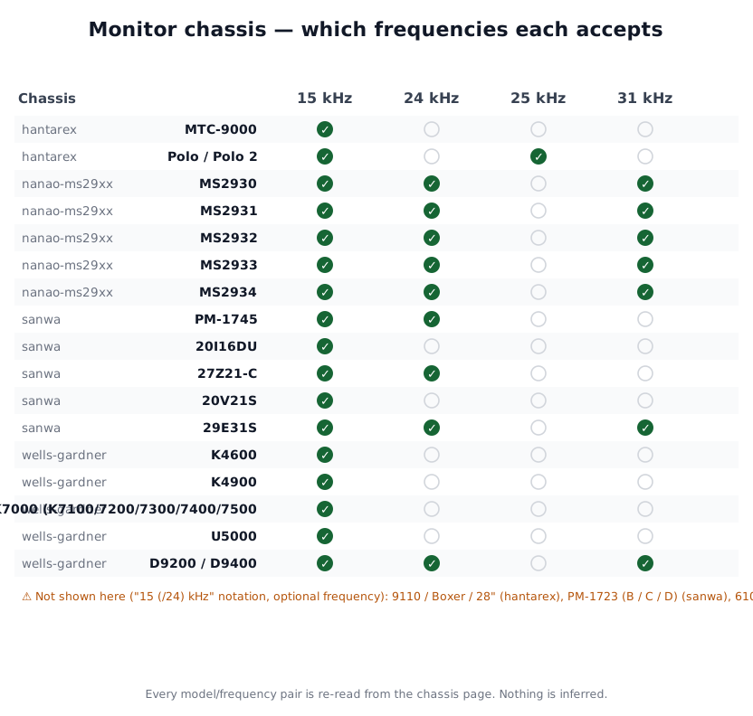
Read from each chassis page's own model table. ⚠️ Three models are missing: their page writes the frequency as "15 (/24) kHz", meaning a second optional frequency depending on the variant — putting those in a binary column would have misled.
Identification / range
| Brand | Chassis (e.g.) | Sizes | Frequencies | Input |
|---|---|---|---|---|
| Wei-Ya / Makvision | M3129 (M3129DF/DB…), 3125B, M2929… | 14" → 29" | 15 / 24 / 31 kHz auto | VGA HD-15 (analog + TTL), separate/composite sync |
| Kortek | tri-sync CRT chassis + arcade LCD panels | 15" → 29" | 15/24/31 kHz (CRT) | VGA |
M3129 specs: CGA/EGA/VGA auto, 640×480 max, 47-70 Hz vertical, ~65 MHz bandwidth, 100-240 V AC, ~120 W, 15-pin D-sub.
Safety (read first)
High voltage — discharge the tube
Lethal high voltage held while unplugged → discharge the anode before work. See CRT safety & HV discharge. Isolation transformer for powered measurements.
Sejoo/Eurocoin \"Vision\" (KTM-F) — the chassis that says the opposite of the old ones
The Eurocoin technical manual 95992001 (Eurocoin part no. 31101210, issue 1/V1-95, 22 numbered pages) is the only manufacturer's manual this wiki holds for a chassis of this generation. On three points it flatly contradicts the Hantarex and Electrohome sets documented here — which is exactly why it must be read before carrying a habit across.
1. The isolation transformer. The manual writes: "The power supply of this chassis design provides isolation, so a separate isolation transformer is not required for normal operation."
⚠️ Compare that with the two other manufacturers' manuals on this wiki: the Hantarex MTC9000 chassis is serviced on an isolating transformer, at 128 V, and the Electrohome G07 manual requires "an isolation transformer must be used". This is not a conflict between sources, it is a difference in design: an isolated switch-mode supply on one side, mains-referenced chassis on the other. ⚠️ Establish which chassis you have before trusting either — and note that the maker writes "for normal operation", not "in all circumstances". None of its other warnings move: the tube remains "a highly evacuated component", the high voltage "capable of delivering LETHAL quantities of energy", and "High Voltage must be completely discharged before handling".
2. No voltage selector. 90-265 V AC, 50/60 Hz, "available power input for the range automatically". Where a Midway MCR is wired by hand (jumpers 5-12 and 10-11 for 230 V), this chassis has nothing to set — and so nothing to get wrong.
3. No width coil. "This monitor utilises unique circuitry such that the horizontal width of the display is regulated by volume control as opposed to variable inductance coils." ⚠️ On this chassis, hunting for a width coil is wasted time: width is on potentiometer RV 701. The G07 does have its L503 coil — both are documented here, do not transpose.
Vision KTM-F — the two commissioning traps
Degaussing will not fire if you switch back on too soon. The automatic circuit "is activated only when the monitor is initially powered up having been off for at least 20 minutes". The PR601 thermistor (positive temperature coefficient) is cold → low resistance → high current through the coil; it heats, its resistance rises, and the current decays to zero before the tube is warm. ⚠️ A tinted screen that "will not degauss" after three power cycles in a row is not broken — PR601 is still hot. Wait, or use a manual coil (and never switch the coil off while the raster still shows its effect).
The X-ray protection latches. Nominal EHT 25 kV; beyond 30 kV, the voltage fed by a resistive divider to pin 8 of IC TDA 2595 trips a circuit that inhibits the oscillator. The manual is explicit: "The circuit continues to block the oscillator until the cause of the failure has been repaired, and can only be reset by completely switching off the monitor and switching on again." ⚠️ A monitor that dies after a few seconds and will not come back on the button has not necessarily lost its EHT: the protection may simply have bitten. It rearms on a full mains-off — but if it bites again, there really is a fault, and the answer is not to work around it.
Vision KTM-F — characteristics, adjustments, pinouts and fault tree, as printed
General technical characteristics
| Item | Printed value |
|---|---|
| Supply | 90-265 V AC, 50/60 Hz, automatic ranging |
| RGB video | analogue positive, 1 to 5 V peak-to-peak |
| Bandwidth (−3 dB) | 12 MHz typical |
| Rise time | less than 50 ns |
| Resolution | 400 × 240 \<CGA> · 480 × 350 \<EGA> |
| Sync | TTL, positive or negative going, separate or composite |
| Sync input impedance | 4.7 kΩ in both polarities |
| Horizontal scan | 15.625 kHz ± 500 Hz \<CGA> · 24.8 kHz ± 500 Hz \<EGA> |
| Width | a single potentiometer, active video 40 to 50 µs |
| Vertical scan | linearity ± 5 %, frequency 45 to 65 Hz |
| Geometric distortion | ± 3 % (max) |
| Picture size regulation | 3 % |
| High voltage | 25 kV, integral X-radiation shutdown |
| Environment | 0 to 55 °C, humidity 10 to 90 %, no condensation |
| Approvals | C-UL E159083 · DHHS 9420433-00 |
⚠️ The document contradicts itself on the line frequency, and this wiki does not arbitrate. The characteristics give 15.625 kHz ± 500 Hz; the adjustments page writes that the monitor "will lock onto signals with horizontal scan rates at 15.75 kHz with no adjustment", and that the capture range "can be increased to between 14.5-16.8 kHz" on RV 401. Both are reproduced as they stand.
User adjustable controls (main PCB unless stated): brightness RV 102 · contrast RV 101 · H-size RV 701 · V-size RV 203 · H-position RV 402 · V-position RV 204 · H-hold RV 401 · V-hold RV 202.
Controls "preset at the factory and should not require further attention": vertical linearity RV 201 and pincushion RV 801 on the main PCB; on the neck PCB, cut-offs RV 301 (R), RV 303 (G), RV 305 (B) and drives RV 302 (R), RV 304 (G), RV 306 (B); screen and focus on the flyback transformer.
Pinouts — mains 2-pin; signal 6-pin: ⚠️ 1 = Blue, 2 = Green, 3 = Red, 4 = ground, 5 = vertical sync, 6 = horizontal sync. The colour order is the reverse of the G07's J201 (1 Red, 2 Green, 3 Blue): never copy a pinout from one chassis to another. Deflection yoke 4-pin: 1 and 2 horizontal, 3 and 4 vertical.
Fault tree, as printed
- No power → fuse F601 4 A / 250 V, then D601, then IC601, then T601.
- No high voltage → B+ on flyback pin 8; if not → AC input and power circuit. Then: pulse on IC401 pin 4 · TR402 base pulse · TR402 collector pulse, about 1050 V peak-to-peak · X-ray hold-down circuit, IC401 pin 8 — positive level 8 V, negative level 4 V** · horizontal deflection connector.
- H or V sync trouble → connector, then the +12 V supply, then IC401 pin 2 (AFC), then the coil on flyback pin 5, then IC401 / IC201.
White balance procedure, as described — steps 1 to 5 with the RGB inputs grounded and the syncs connected at nominal rate; steps 6 to 8 with a pattern generator ("if a pattern generator is not available, acceptable results may be obtained using the game programme"): 1. the three cut-offs RV 301 / 303 / 305 to minimum, fully counter-clockwise; 2. the three drives RV 302 / 304 / 306 to their middle settings; 3. brightness RV 102 and contrast RV 101 to minimum; 4. slowly raise the flyback screen control until the raster is just visible — the colour that appears is the lead colour, and its cut-off stays fully counter-clockwise for the rest of the procedure; 5. set brightness for a dim raster, then the two remaining cut-offs for the most uniform grey; 6. on a colour bar pattern, set the drives for the most neutral white; 7. set brightness and contrast for the wanted illumination; 8. repeat 5 and 6 if needed.
⚠️ Sejoo KTH-2002 — the same designator, two opposite functions across models
The Color Raster Display Monitor Instruction Manual from Sejoo Corporation (24 pp.) covers the 10″, 14″ and 20″ of the KTH-2002 range. Set beside the "Vision" KTM-F above, it reveals a trap this wiki had not seen at any other maker:
| Designator | On the "Vision" KTM-F | On the KTH-2002 |
|---|---|---|
| RV 202 · RV 203 | vertical hold · height | ✅ identical |
| RV 401 | horizontal hold | ✅ identical |
| RV 402 | horizontal centering | ✅ identical (horizontal video shift) |
| ⚠️ RV 701 | ⚠️ width (potentiometer) | ⚠️ brightness |
| Width | RV 701, a potentiometer | ⚠️ RV 403, a coil with a hexagonal tuning tool |
| Brightness | RV 102 | ⚠️ RV 701 |
⚠️ Four designators out of six agree, and the two that diverge are exactly the ones you would turn first. On a KTH-2002, turning "RV 701" believing you are setting width darkens the picture; on a Vision, you widen the picture believing you are setting brightness.
⚠️ And width is not even set by the same organ: the Vision proudly announced "regulated by volume control as opposed to variable inductance coils"; the KTH-2002 does have a coil, "a hexagonal tuning tool adjustment". Hunting for a width coil is wasted time on one and the correct move on the other.
✅ The only rule that holds is the one this wiki has repeated for three days: read the designators on the chassis you have, never from the neighbouring model's manual.
KTH-2002 — data sheet, and the X-ray circuit's values
| Item | Value |
|---|---|
| Tubes | 10″ 270BB22 · 14″ 37GGA85xX-TC — 0.68 mm pitch · 20″ 51GGB95xX-TL — 0.82 mm pitch |
| Resolutions | 10″ 280 × 240 · 14″ and 20″ 400 × 240 |
| Mains | 90 to 245 V AC, 50-60 Hz, 100 W max. |
| Video | RGB analogue 1 to 5 V p-p, adjustable on the gain |
| Sync | TTL positive or negative, separate or composite, 4.7 kΩ in both polarities |
| Horizontal scan | 15.625 kHz ± 500 Hz standard — ⓘ "higher scan frequencies available" |
| Width | a coil, active video 40 to 50 µs |
| Vertical scan | 45 to 65 Hz, linearity ± 5 % |
| Geometric distortion · picture size | ± 3 % · 3 % |
| ⚠️ Video bandwidth | ⚠️ 16 MHz typical at −3 dB — ⓘ the Vision gives 12 MHz |
| Rise time | less than 50 ns |
| Environment | 0 to 55 °C · complies with UL, CSA and D.H.H.S. (composite video) |
✅ And it gives what the Vision described in words only: the X-ray protection circuit with its values. Same TDA 2595, same pin 8, same 30 kV threshold, same latch until repair — but here the divider is quantified: R406 10 kΩ 1 % and R407 2.2 kΩ 1 % from the +12 V, C409 22 µF, R420 220 kΩ 1 % and C804 1 µF toward pin 2 of the flyback, with diodes D401, D405 and D803.
ⓘ A usage warning the Vision does not give: "Do not use the horizontal hold control for horizontal centering." Centering has its own control, RV 402.
⚠️ Sejoo KTN-20 — third model, third designator map
The KTN-20 manual (Sejoo/Kortek, 17 pp.) is the third from this house archived here. ⚠️ And it shares its designator map with neither of the other two:
| Function | "Vision" KTM-F | KTH-2002 | ⚠️ KTN-20 |
|---|---|---|---|
| Horizontal hold | RV 401 | RV 401 | ⚠️ RV 402 |
| Horizontal centering | RV 402 | RV 402 | ⚠️ RV 416 |
| Width | RV 701 (potentiometer) | RV 403 (coil) | ⚠️ L 401 (coil) |
| Vertical hold | RV 202 | RV 202 | ⚠️ RV 201 |
| Height | RV 203 | RV 203 | ⚠️ RV 202 |
| Vertical raster position | — | — | RV 203 |
⚠️ Every designator has shifted by one. On a KTN-20, RV 402 is the horizontal hold — on the other two it is the centering. RV 202 is the height — elsewhere it is the vertical hold. ⓘ These are the most treacherous shifts there are: the control responds, the picture changes, but not as expected, and you blame a maladjustment.
✅ Three manuals from the same maker, three designator maps. The only reliable instruction remains the one this wiki repeats: read the designators on the chassis you have.
KTN-20 — two supply peculiarities and one discharge instruction
⚠️ It has two separate mains inputs:
| Voltage | |
|---|---|
| Voltage 1 — main supply | 105 to 135 V AC |
| ⚠️ Voltage 2 — degaussing | ⚠️ 220 V AC ± 10 % |
ⓘ Degaussing has its own 220 V supply, separate from the 105-135 V of everything else. A degauss that does not fire may therefore come from an input that has nothing to do with the one running the monitor. 50 to 60 Hz for both.
✅ And its discharge instruction names the right point: "Always discharge the picture tube anode to the CRT conductive coating before […]" — the tube's conductive coating, that is the aquadag, and not the chassis. ⓘ That is exactly the point the CRT safety page prescribes, and the same as the WG 19V2000, which adds the 10 kΩ resistor to it.
⚠️ Two high-voltage bounds, not one: "The nominal value of the high voltage of this receiver is 25 kV at zero beam current. The high voltage must not, under any circumstances, exceed 30 kV." ⓘ A nominal value and an absolute ceiling — most of the wiki's manuals give only the first.
Adjustments, in the manual's order: 120 V supply on RV 601 · line oscillator RV 402 · width L 401 · horizontal position RV 416 · vertical oscillator RV 201 · height RV 202 · vertical position RV 203 · white balance RV 105, RV 106, RV 107, RV 108, RV 109 · black level RV 104.
Common faults
| Symptom | Likely cause | Lead |
|---|---|---|
| No picture / repeated blow-ups | poor-quality HOT (H output transistor) — the No. 1 fault of all tri-syncs | Replace the HOT (keep spares); find what killed it (deflection, +B) |
| Unstable image / flicker | mediocre capacitors | Recap (essential on any Makvision) |
| Intermittent dropouts | factory lead-free solder (cracked joints) | Reflow and re-tin with 60/40 on every joint |
| Only locks on one frequency (e.g. 31 kHz) | tri-sync switching / sync | Check sync type (separate/composite), the frequency-detect stage |
| Geometry/convergence off | OSD settings or pots | Adjust via the OSD/menu or coils/pots |
Procedure — working through a chassis ✅
Discharge the anode before anything else
The tube holds its charge with the cabinet unplugged, and so does the main filter capacitor. Discharge it, keep one hand in your pocket, and do not work on it alone. → CRT safety
Hot chassis: the ground is not earth
Some arcade chassis are referenced to the mains. On those, chassis ground is not earth, and an earthed oscilloscope clipped to it makes a dead short through your probe. Work through an isolation transformer. → CRT safety
1. Cold, before switching on. Cracked solder joints are the fault on these chassis — around the connectors, the flyback and anything heavy enough to work its own joints loose. Also swollen capacitors, cooked resistors, the brown halo of something that has been running hot. Reflow what looks suspect before diagnosing: a good share of intermittent chassis faults end there.
2. Fuse and primary side. A fuse that goes again is a short downstream, not a fuse problem — find it before fitting another.
3. Is there EHT at all? The tick of the flyback at switch-on, the filament glowing in the neck. No EHT points at the supply or the line stage. EHT but no picture points at video or the G2 — two very different jobs, and this is the measurement that separates them.
4. Recap — before any adjustment. This page carries the capacitor list — take the one matching your exact chassis if it covers more than one. On a chassis of this age recap is not optional: the electrolytics are thirty years old and have been running hot since day one. → Recap
5. Adjustments, and only now. ⚠️ Never before the recap. Setting the geometry of a chassis whose capacitors are dying records the drift and makes you do the whole job twice. Write down where every pot was before you touch it. → CRT safety
6. Scan rate. This page covers several chassis with different capabilities — take the line for yours from its table. A board whose rate the chassis does not accept shows nothing, and nothing is faulty.
7. Verification. Let it run warm for a good while and check the geometry stops moving. A chassis that is right cold and wrong after twenty minutes is still a thermal fault — usually a joint, sometimes a capacitor you left in.
Repair (method)
- HV discharge → CRT safety.
- HOT: the structural weakness. On a blow-up, fit a quality HOT (a robust equivalent) and find the cause (deflection, +B, driver) before powering up — or it blows again.
- Recap (method): the factory caps are mediocre → a cap kit is recommended on any Makvision/Wei-Ya.
- Redo ALL joints: these chassis use problematic lead-free solder → reflow + add 60/40 (frequent cold joints).
- Adjustments: auto frequency (check the incoming sync), geometry via OSD/pots.
Upside (preservation)
- 15/24/31 kHz tri-sync + VGA input: one CRT for classic 15 kHz and 31 kHz (Naomi, Type X, arcade PC). A CRT option when an original chassis (Nanao/WG) is beyond repair.
Cap kits & parts
- Makvision cap kits (generic arcade vendors); spare HOTs (keep stock).
- ⚠️ Cross-check against your board: several revisions/sizes.
See also
- CRT safety · Recap · Traces & vias · original chassis: Nanao MS8/MS9, Wells-Gardner, Sanyo 20-EZ, Hantarex.
Archived original documents ✅
Manufacturer documents archived locally, found in Internet Archive's arcademanuals collection on 14 August 2026. ⚠️ The items declare no licence.
- PDF — kortek-sejoo-ktm-f-vision-series-manual.pdf — VISION SERIES — A Fine Quality Colour Monitor, "Manufactured in Korea for Eurocoin Limited by Sejoo Corporation", distributed in Europe by Eurocoin Ltd (Barnet, Hertfordshire), 27 pp. ⚠️ The word "Kortek" appears nowhere in this document. The cover carries only two names — the Korean maker Sejoo and the European distributor Eurocoin — and the only model designation printed is KTM-F, on the schematic. The attribution to Kortek comes from the Internet Archive item title, not from the document; the filename keeps it for that reason alone. ✅ But the link between the two names is documented elsewhere: another Sejoo manual archived since carries, in its footer, "SEJOO CORPORATION — GURO P.O.BOX 82, SEOUL KOREA — TELEX: K33454 KORTEK". ⓘ "Kortek" was Sejoo Corporation's telex answerback — that is where the name the brand later traded under comes from. It is under "Vision" that you find it in British cabinets. Via Internet Archive
- PDF — sejoo-kth-2002-color-raster-display-10-14-20-pouces.pdf — SEJOO CORPORATION — Color Raster Display Monitor Instruction Manual, KTH-2002 range, 10″, 14″ and 20″, 24 pp. ✅ This is the document that carries, in its footer,
TELEX: K33454 KORTEK— the origin of the name the brand became known by. ⚠️ And it shows that RV 701 does not have the same function as on the "Vision" KTM-F. Harvested from Internet Archive's arcademanuals collection. - PDF — sejoo-kortek-ktn-20-color-raster-display.pdf — Kortek SEJOO KTN-20 Color Raster Display Monitor Instruction Manual, 17 pp. ⚠️ A third designator map from this house: RV 402 is the horizontal hold there, RV 202 the height. ⓘ And it has two mains inputs — 105-135 V for the monitor, 220 V for degaussing. Harvested from Internet Archive's arcademanuals collection.
Sources & attribution
- forum.arcadecontrols.com / Arcade-Museum — Wei-Ya/Makvision M3129 & 3125B chassis (weak HOT, recap, lead-free solder, tri-frequency sync) — https://forum.arcadecontrols.com/index.php?topic=166359.0
- Makvision M3129 product data (15/24/31 kHz, 640×480, VGA) — spec cross-check
- Wei-Ya / Makvision / Kortek — service manuals — to reference
Review & corrections
How this space is used
Spotted a wrong value, an outdated procedure, a chip reference that does not match your board? Say so here, with what you observed (model, board revision, serial number, measurement). Every report is cross-checked against a source before anything changes — an unverifiable correction is published as “reported by …, not cross-checked” rather than silently applied.
Reading is open to everyone; posting requires signing in with Discord. Reports from the wiki's declared reviewers are handled first; anyone else's are read too, but go through a human before anything is changed.