Nintendo NES / Famicom
Nintendo's 8-bit console (Famicom in Japan, 1983; NES in export, 1985). Two well-known traps: the NES's 72-pin connector that wears out (the "blinking light") and the lack of native RGB → hence the NESRGB mod.
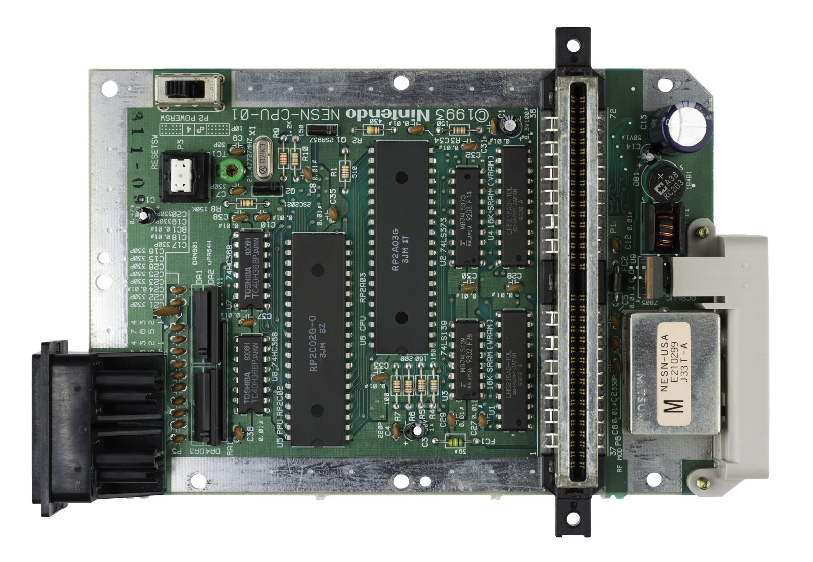
Identification
| Field | Value |
|---|---|
| Manufacturer | Nintendo |
| Release | 1983 (Famicom, JP) / 1985 (NES) |
| Generation | 3rd (8-bit) |
| Revisions | NES front-loader (toaster) · NES-101 top-loader · Famicom / AV Famicom |
| Native video output | Composite / RF — no native RGB |
| Region / lockout | 10NES (NES) + NTSC/PAL; Famicom without lockout |
| Media format | Cartridge (NES 72-pin, Famicom 60-pin) |
Architecture (detail)
| Block | Chip (part #) | Clock | Role |
|---|---|---|---|
| CPU | Ricoh RP2A03 (NTSC) / RP2A07 (PAL) | 1.789773 MHz (NTSC) / 1.662607 MHz (PAL) | MOS 6502 core without decimal (BCD) mode + integrated APU |
| Video | PPU RP2C02 (NTSC) / 2C07 (PAL) | 5.369318 MHz (= 3× CPU in NTSC) | Directly generates composite NTSC/PAL |
| CPU RAM | 2 KB SRAM | — | $0000-$07FF (mirrored ×4 up to $1FFF) |
| Video RAM | 2 KB SRAM (nametables) | — | + 256 B OAM (sprites), 28 B palette |
APU (inside the 2A03): 5 channels — 2 pulse, 1 triangle, 1 noise, 1 DPCM (samples). Mixing is non-linear.
PPU 2C02: 256×240 framebuffer (often 256×224 visible in NTSC, overscan); 64 sprites (max 8 per line → flicker), 25 simultaneous colours from a 54 palette. No RGB output (direct composite).
Memory & mappers
The CPU bus: $0000-$1FFF RAM, $2000-$2007 PPU registers, $4000-$4017 APU/controllers,
$4020-$FFFF = cartridge (PRG-ROM + WRAM). The cartridge carries a mapper (bank
switching) that extends the addressing:
| Mapper | Name | Examples |
|---|---|---|
| 0 | NROM | Super Mario Bros., Donkey Kong |
| 1 | MMC1 | Zelda, Metroid, Mega Man 2 |
| 2/3 | UxROM / CNROM | Castlevania, Contra (JP) |
| 4 | MMC3 | SMB3, Kirby, Mega Man 3-6 |
| 5 | MMC5 | Castlevania III (+ expansion audio) |
| 9/10 | MMC2 / MMC4 | Punch-Out!!, Fire Emblem |
The iNES format (.nes) encodes the mapper number in its header; several
hundred mappers are catalogued today (official Nintendo MMCx + third-party chips
Konami VRC, Namco 163, Sunsoft…). Some mappers add a scanline IRQ (MMC3) used
for split-screens (SMB3's status bar).
Video & output
- PPU → composite / RF only (no native RGB; the 2C02 encodes composite internally).
- NES-001: RF + composite + mono audio (RCA on the multi-out).
- NES-101 (top-loader): composite only (no RF), but "jailbars" (vertical bars) — a known artifact.
- RGB: only via a mod (NESRGB, an FPGA sitting on the PPU) or the RGB PPU of the Famicom Titler / PlayChoice-10.
- Native RGB PPUs: RP2C03 / 2C04 / 2C05 variants (arcade PlayChoice-10 and Nintendo VS. System) output RGB — but with different palettes (sometimes deliberately scrambled on VS for protection).
- PAL: 50 Hz, the full 256×240 image (less overscan than NTSC), and gameplay ~17 % slower (music and speed) unless the title was reprogrammed — hence the rare "optimised" PAL versions vs plain ports.
Region & 10NES lockout
- The 10NES (CIC) is a microcontroller present in both the console and the cartridge: both run a compared stream in lockstep. On disagreement (different region, or bad cartridge contact), the console CIC resets the CPU in a loop → the famous blinking LED.
- NTSC vs PAL: different CIC keys and clocks.
- Disabling: cut/ground pin 4 (reset) of the console CIC → no more lockout (region-free + end of false blinking due to the connector). The NES-101 and the Famicom have no 10NES.
Expansion audio (Famicom)
The Famicom cartridge (pin 45) can add channels: VRC6 (Castlevania III JP), VRC7 (FM), N163, FDS, MMC5, Sunsoft 5B. The 72-pin NES doesn't route this signal → a mod is needed to hear it.
Famicom Disk System (JP add-on)
A Famicom add-on (1986, Japan): a double-sided 2.8″ "Quick Disk" drive (~112 KB total) via a RAM adapter plugged into the cartridge port.
- Why? At the time, storage cheaper than ROM + saving possible + one extra wavetable audio channel. Zelda, Metroid, Kid Icarus first shipped on FDS.
- Rewrite kiosks (Disk Writer): you'd buy a new game by rewriting its disk for ~500 ¥ — a unique distribution model.
- ⚠️ Cult fault: the drive's rubber belt disintegrates → dead drive. Belt replacement is the #1 FDS repair. The unprotected disks are trivially copied/pirated (a known weak point).
Peripherals
- Zapper (light gun): works only on a CRT (it senses the beam scan) — unusable on an LCD without a dedicated solution.
- Controller 2 (Famicom HVC-001): built-in microphone (used by a few games, e.g. squashing enemies in Zelda), no Start/Select buttons.
- Expansion port: Famicom = DA-15 connector (Zapper, keyboard, third-party pads); NES = a front expansion port (rarely used).
- Others: R.O.B. (robot), Power Pad, Four Score (4 players), NES Advantage (arcade stick with turbo).
Preservation & homebrew
- Flashcarts: EverDrive N8 / N8 PRO (Krikzz), PowerPak — load the library
- homebrew from an SD card, with mapper emulation (including expansion audio on the PRO models).
- A very active homebrew scene (NESmaker, demos), and very mature reference emulation (Mesen, FCEUX, Nestopia, MAME).
Detailed revisions
- NES-001 (front-loader): 72-pin ZIF connector, 10NES, RF+composite. The ZIF loses its tension → bad contact → blinking.
- NES-101 (New-Style, 1993): top-loader, no 10NES, no expansion port, composite only, jailbars.
- Famicom HVC-001: 60-pin, RF only, native expansion audio.
- AV Famicom HVC-101: composite, no RF.
Faults & diagnosis
| Symptom | Root cause | Diagnosis / repair |
|---|---|---|
| Blinking LED, game won't start (NES-001) | Loosened 72-pin connector → bad contact → 10NES reset | Replace the connector ("Blinking Light Win"); or disable the 10NES (pin 4) |
| Intermittent corrupted graphics | Cartridge / connector contacts | Clean cartridge edge (iso alcohol) + connector |
| Poor RF image | RF output | Composite/AV mod or NESRGB |
| Jailbars (NES-101) | Power/ground artifact | Filtering / mod |
| Yellowed plastic | ABS photo-oxidation | Retrobright |
| Won't power on | 7805 regulator, power, fuse/diode | Check +5 V, regulator |
(Few electrolytic capacitors: recap secondary, except regulator/power.)
Step-by-step disassembly procedures ✅
1 procedures transcribed from the iFixit guides, with difficulty and estimated time.
| Procedure | Difficulty | Time |
|---|---|---|
| Nintendo Family Computer (Famicom) Teardown | Moderate | — |
Nintendo Family Computer (Famicom) Teardown
It's day four of our week of game console teardowns . We stole borrowed a hot tub time machine, went directly to 1983, and acquired a Japanese national treasure: the Famicom! We partnered with Wired for this teardown to bring you a glimpse of one of the most popular game consoles ever. Check out their story ! For those of you born in this century, the Famicom -- short for Family Computer -- is the name of the Nintendo Entertainment System ( NES ) in Japan. Join us as we delve into the system that revolutionized the gaming world as we know it.
- Our contestant hails from a mystical place, the land of the rising sun, Japan!
- The Nintendo Family Computer, released in 1983 in most of Asia, is the overseas brother of the Nintendo Entertainment System.
- Technical Specifications:
- Ricoh 2A03 8-bit 1.79 MHz processor (based on the MOS Technology 6502 8-bit processor core)
- 2KB (16Kb) on-board RAM
- 2KB (16Kb) on-board Video RAM
- PSG Sound
- 256 x 240 pixels resolution
- Backside ports include:
- AC adapter port
- TV/Game switch
- Channel selector switch
- RF Audio/Video output
- Why are you looking so scared, little buddy? Don't worry -- our hands are gentle. We won't hurt you.
- Fully assembled Nintendo Famicom console.
- The Famicom was the first console to popularize D-pad controllers to acquire user input. Departing from the era of joysticks, the inclusion of the D-pad allowed for quick and accurate controls.
- The controllers are similar, but not the same...
- The first controller boasts the traditional layout: D-pad on the left, "select" and "start" buttons in the center, and "b" and "a" buttons on the right.
- However, the second controller has a built-in microphone and a volume switch at the expense of the central "select" and "start" buttons... Cool!
- This is the only console we know of that has a microphone on one of its standard controllers.
- The Famicom's miniscule 4W power supply won't be popping fuses anytime soon.
- That's about 2.5% of the power that the Xbox 360 devours.
- Nintendo Famicom model number HVC-001, Made in Japan. We wouldn't want our Famicom any other way.
- A quick removal of six Phillips screws and the bottom cover lifts right off.
- Just like the earlier retro consoles , Fami is super-easy to disassemble.
- (yes, we named him Fami.)
- Two antiquated connectors exchange signals between the controllers and the board.
- Want to disconnect a controller? Gotta remove the bottom cover -- but that's pretty much it.
- Controller II has an extra wire for microphone input and controlling the volume.
- After disconnecting them from the board, the controller cables can be lifted out of the case.
- Six Phillips screws secure the motherboard assembly to the outer case.
- Lifting the assembly out of the case gives us a good look at the archaic silicon that makes this thing tick.
- Two more Phillips screws secure the hefty power switch to the outer case.
- Notable chips on the board include:
- Ricoh RP2A03G 8-bit, 1.79 MHz CPU
- Ricoh RP2C02G-0 8-bit, 5.32 MHz PPU
- Toshiba TC40H368P hex bus buffers
- Sharp LH5216D-12 static RAM
- Hitachi HD74LS139P decoder/demultiplexer
- Fujitsu MB74LS373
- Unsurprisingly, lead solder abounds on the bottom of the board. RoHS standards weren't established until 20 years after this puppy was made.
- Well hello there!
- "Shall I compare thee to an Xbox 360? Thou art more lovely and more temperate...But thy internal structure shall not fade...Nor shall time brag thou wand'rest in its shade...So long as gamers can breathe or eyes can see, So long lives this, and this gives life to thee."
- After the motherboard assembly is out, the reset and power button covers can easily be removed.
- Unclipping a spring is all that's needed to remove the eject mechanism from the outer case.
- Ejecting a cartridge is accomplished by pushing two inclined planes underneath the cartridge until it pops up off the connector attached to the board.
- Breaking Gently releasing the retaining clips holding the cartridge together reveals a 60 pin printed circuit board.
- Front and back sides of the Famicom cartridges:
- This PCB from a Tennis cartridge has two ROM packages -- totaling 24 KB -- soldered to one side.
- For comparison, a single layer Blu-ray disc has a 25,000,000 KB capacity.
- Breaking Gently releasing the retaining clips holding the cartridge together reveals a 60 pin printed circuit board.
- Front and back sides of the Famicom cartridges:
- This PCB from a Tennis cartridge has two ROM packages -- totaling 24 KB -- soldered to one side.
- For comparison, a single layer Blu-ray disc has a 25,000,000 KB capacity.
Source, licence and scope
iFixit guides, under Creative Commons BY-NC-SA — attribution, non-commercial, share-alike. Only the text is reproduced; the step photos stay on iFixit. ⚠️ These guides target the model named in the title: on another revision, the screws and the order of removal may differ.
Mods — what to buy, how
Blinking ≠ dead lockout chip
A front-loader that blinks (red light, grey screen) is, in the vast majority of cases, the tired/oxidised 72-pin connector, not the 10NES chip. Clean the cartridge (never blow into it), then replace the connector before any other diagnosis.
- 72-pin connector replacement 🟡: unclips the old connector from the RF block (no soldering on the front-loader), fit a new one. Avoid the too-tight "bendy"/new-OEM ones that scratch carts; use a quality spring connector. Addresses the root cause of the blinking.
- NESRGB (Tim Worthington) 🟠: an FPGA board that caps the PPU (desolder the stock PPU, fit the board in its place, solder the output flex) → clean RGB / component, selectable palettes. The reference AV mod. → NESRGB technical page.
- 10NES (lockout) disable 🟡: on the front-loader, cut pin 4 of the 10NES (CIC) chip → the console stops resetting (no more blinking) + tolerates other-region carts. The classic documented mod. → Region-free & lockout.
- Composite/AV out on RF-only units (top-loader NES-101, Famicom) — exact procedure below.
- Expansion audio (hear Famicom VRC6/VRC7/N163/FDS chips on the NES) — exact points below.
- "Stereo" sound (2 channels) — exact points below.
Famicom expansion audio on NES — exact points (transcribed from ConsoleMods, CC-BY-SA)
The 60-pin Famicom cart connector has pin 45 (audio console→cart) and pin 46 (audio cart→console); the 72-pin NES lacks these → expansion audio is silent on the NES. You mix it back via the expansion port underneath.
-
NES front-loader: solder a 47 kΩ resistor between expansion pin 9 (EXP6) and pin 3 (audio mix input). Noise fix recommended: a 1 kΩ pull-down between EXP6 (pin 9) and pin 2 (GND). (⚠️ don't confuse EXP6 = pin 9 with EXP9 = pin 6!) Ready-made: ENIO (47 kΩ pre-wired, no soldering) or Voultar's board.
-
NES top-loader (no real expansion port): use EXP9 = cartridge pin 51. Solder a 1.2 kΩ resistor between pin 51 (EXP9) and the audio-out pin (right next to pin 51). With PowerPak / EverDrive N8: also wire the flashcart between pin 51 (EXP9) and pin 54 (EXP6).
-
Level tip: replace the fixed resistor with a potentiometer (plus a series resistor so 0 Ω = too loud isn't possible). Keep resistors as close as possible to the point (else noise).
NES \"stereo\" sound (2 channels) — transcribed from ConsoleMods, CC-BY-SA
The CPU synth puts out two separate signals: AUX 0 (AUX A on Famicom) = the 2 square waves; AUX 1 (AUX B) = triangle + noise + DMC. Separating them gives 2-channel sound (not true spatial stereo).
-
"Plain" mod: disconnect the CPU sound output from the stock mixer; add a 1 µF series cap per channel (negative toward the console, protection + slight low-pass); wire the output jack.
-
"Mixback" mod (keeps mono): tap AUX0/AUX1 without disconnecting them; caps + jack; (log) potentiometers bringing the existing mono to the centre tap (points AA/BB on the schematic — on NES AA = BB; on Famicom AA = cleaner but no expansion, BB = with expansion).
Top-loader (NES-101) AV mod — anti-jailbars, exact points (transcribed from ConsoleMods, CC-BY-SA)
The NES-101 top-loader is RF-only with heavy jailbars: the PPU's composite-video trace is thin and runs alongside address-bus lines → digital noise. The key: isolate PPU pin 21 (video out) from the board, then amplify/buffer it.
PPU: labelled RP2C02G-0. With the controller ports facing you, pin 21 = the leftmost pin on the side facing you (= video out).
Video-amp BOM (if DIY; otherwise a prebuilt Voultar / Cathouse Games board):
- 1× PNP 2N3906 transistor (or a 2SA937 salvaged from the board)
- 1× 220 µF cap · 1× 110 Ω · 1× 300 Ω · 1× 560 pF cap
Procedure:
- Disassemble (4.5 mm gamebit bits), remove shields + the 7805 heat sink.
- Desolder the RF modulator (3 pins audio/video/5 V + ground lugs) and free the rear panel.
-
Isolate PPU pin 21: simplest — snip it close and lift it; cleanest — desolder the PPU, lift pin 21, reinstall (or use a 40-pin DIP socket). Tin pin 21.
-
Mount the video amp (on top of the PPU, foam tape) with no shorts. Pin 21 → amp video input; +5 V → amp power; ground → amp ground.
-
Output: amp video out → video pin of the AV jack (a 3.5 mm TRRS where the RF RCA was, or a printed multi-out/RCA panel).
-
Audio (no amp needed): leftmost pin of the RF modulator → AV audio (or the top lead of FC1, nearest the cartridge port). Ground → AV ground.
-
Check continuity with a multimeter; refit the 7805 heat sink before testing.
Procedure — a dead console, step by step ✅
What this adds
Ordered for a console, not for an arcade board: what kills these is almost never the CPU. It is, in real order, the power supply, the capacitors, the drive or the cartridge slot, and only then the logic. → PCB diagnosis
1. The power supply. Two cases, depending on the machine. External brick: ⚠️ read the marking on the machine, next to the socket, and check the adapter against it — voltage and polarity. A centre-negative machine fed centre-positive loses its fuse, sometimes its regulator; do not trust a third-party label or a generic tip. Internal supply (the machine plugs straight into the wall): mains is inside the shell. Unplug, wait, and confirm the large capacitors are discharged before touching the board. Either way, measure under load: a failing supply holds its voltage until it is asked for current.
2. The fuse. Many of these machines have one right behind the socket — it is the part designed to die. Test it in continuity, out of circuit. A fuse that blows again is a short, not a fuse problem.
3. Capacitors. On most machines of this age this is the default suspect rather than a last resort — leaking SMD electrolytics eat the tracks underneath before they give any other sign. ⚠️ Not all of them are like that: some carry very few and are not recapped on principle. Read what this page says about it before reaching for the iron. → Recap
4. The cartridge connector. Cartridge contacts with isopropyl alcohol, never an abrasive eraser: it takes the gold plating off and the problem comes back worse. On the machine side, inspect the slot pins — splayed, bent or oxidised — and check continuity between slot and board.
5. Video output. Isolate the machine from the display: another cable, another TV, another input. A sizeable share of "dead consoles" are a dead cable, or a display that will not lock onto what this machine outputs — see the video section of this page for what that is.
6. Still nothing. Now, and only now, the logic: rails on the board, reset, clock, bus. → PCB diagnosis
Photos / assets
(To add: NES front-loader vs NES-101 board, 72-pin connector, PPU.)
Advanced repair
72-pin connector (No. 1 cause: blinking/grey screen) → clean or replace; the 10NES lockout chip (blinking) = a mod option. Methods: PCB fault-finding · Traces & vias · Recap.
Archived manufacturer documentation ✅
Manufacturer documentation archived locally.
- NES — PDF
Status
Manufacturer documents with no explicit licence, kept for preservation.
Sources & attribution
- Wikipedia — Nintendo Entertainment System — CC-BY-SA — https://en.wikipedia.org/wiki/Nintendo_Entertainment_System
- ConsoleMods — NES: (Composite) Top Loader AV Mod (PPU RP2C02G-0 pin 21 = video out to isolate, PNP amp 2N3906/2SA937 + 220 µF/110 Ω/300 Ω/560 pF, audio = leftmost RF-modulator pin or top lead of FC1) — CC-BY-SA — https://consolemods.org/wiki/NES:(Composite)_Top_Loader_AV_Mod
- ConsoleMods — NES: Expansion (EXP) Audio Mod (Famicom pins 45/46; front-loader 47 kΩ EXP6[pin 9]↔EXP3 + 1 kΩ pull-down to GND[pin 2]; top-loader 1.2 kΩ on pin 51[EXP9]) — CC-BY-SA — https://consolemods.org/wiki/NES:Expansion_(EXP)_Audio_Mod
- ConsoleMods — NES: "Stereo" Audio Mod (AUX0/AUX A = 2 squares, AUX1/AUX B = triangle+noise+DMC, 1 µF series cap/channel negative toward console) — CC-BY-SA — https://consolemods.org/wiki/NES:%22Stereo%22_Audio_Mod
Image:
-
nes-board.jpg— Evan-Amos, public domain — https://commons.wikimedia.org/wiki/File:Nintendo-NES-Mk2-Motherboard-Top.jpg

Review & corrections
How this space is used
Spotted a wrong value, an outdated procedure, a chip reference that does not match your board? Say so here, with what you observed (model, board revision, serial number, measurement). Every report is cross-checked against a source before anything changes — an unverifiable correction is published as “reported by …, not cross-checked” rather than silently applied.
Reading is open to everyone; posting requires signing in with Discord. Reports from the wiki's declared reviewers are handled first; anyone else's are read too, but go through a human before anything is changed.