Sinclair ZX Spectrum
The British 8-bit icon (1982): a Z80, a single ULA doing video + I/O, and a colossal library. Standard Sinclair repair: the ULA (heat-fragile), the lower RAM, the regulator and the membrane keyboard.
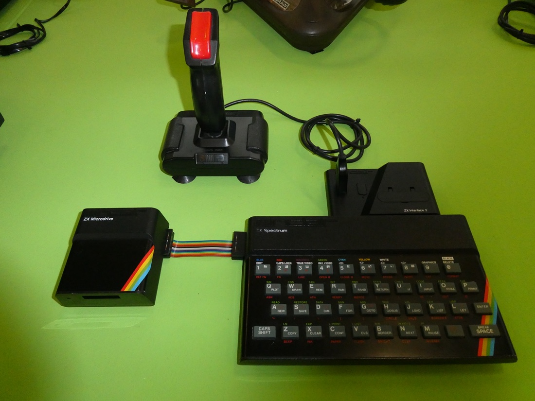
ZX Spectrum (1982) — photo by Jzh2074, CC BY-SA 4.0 (Wikimedia Commons).
Identification / models
| Model | Year | RAM | Note |
|---|---|---|---|
| 16K / 48K ("rubber keys") | 1982 | 16/48 KB | rubber keys, ULA |
| 48K+ | 1984 | 48 KB | revised keyboard |
| 128 ("toastrack") | 1985 | 128 KB | AY-3-8912 sound, memory banks |
| +2 (grey) / +2A (black) | 1986-87 | 128 KB | built-in tape deck |
| +3 | 1987 | 128 KB | 3″ disk drive (like Amstrad) |
CPU Z80 @ 3.5 MHz; video 256×192, 15 colours with the signature "attribute clash".
Repair (technician)
The ULA — the emblematic fault
The ULA (Ferranti) generates video and I/O; it runs hot and fails (no/corrupt picture, crashes). Cool it (heatsink), and as a last resort replace it (used ULA or a modern replacement like nu-ULA/vLA82).
- Lower RAM (16 KB): 4116 DRAM (needs +5/+12/−5 V) → faulty = checkerboard / crash; substitution. The upper (48K) RAM is 4164.
- 7805 regulator ("black guardsman"): runs hot → heatsink/ventilation; external 9 V supply.
- Membrane keyboard: the No. 1 usage fault → replacement membrane (new ones available).
- +2A/+3: mains RIFA in the PSU (smoke) → replace; 3″ drive (+3) = belt.
- Video output: composite/RF stock → RGB/SCART mods (video mods).
Original service manual ✅
Manufacturer manual archived locally. It typically carries the schematics, the block diagram, the expected voltages and waveforms, the parts list and the disassembly procedures — the reference when a symptom matches no known fault.
- ZX Spectrum 128 — service manual — PDF · variant
- ZX Spectrum 128 +2 — service manual — PDF
- Schematics: Issue 1 — PDF · +2A / +3 — PDF · +2B — PDF · +3B — PDF
- Technical documentation: 128 — PDF · +2A — PDF
- Video — ⚠️ community work, not Sinclair documents: RGB on the 128 — PDF ("MTs", 2003) · 128K video fixes and cables — PDF ("bverstee", 2021)
- Pratique du Spectrum, vol. 1 (PSI, 1984) — PDF
The Issue 1 schematic is not your machine's
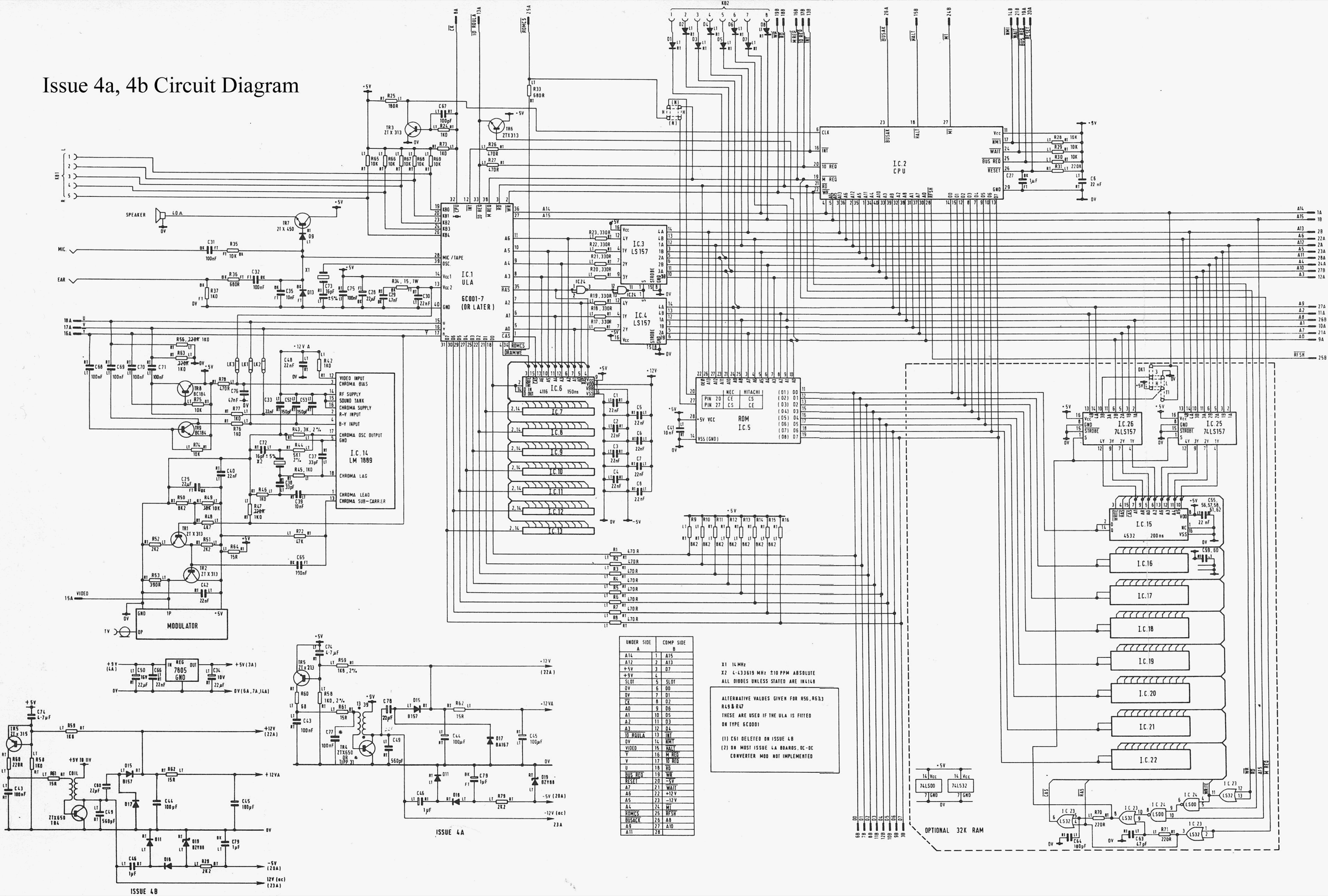
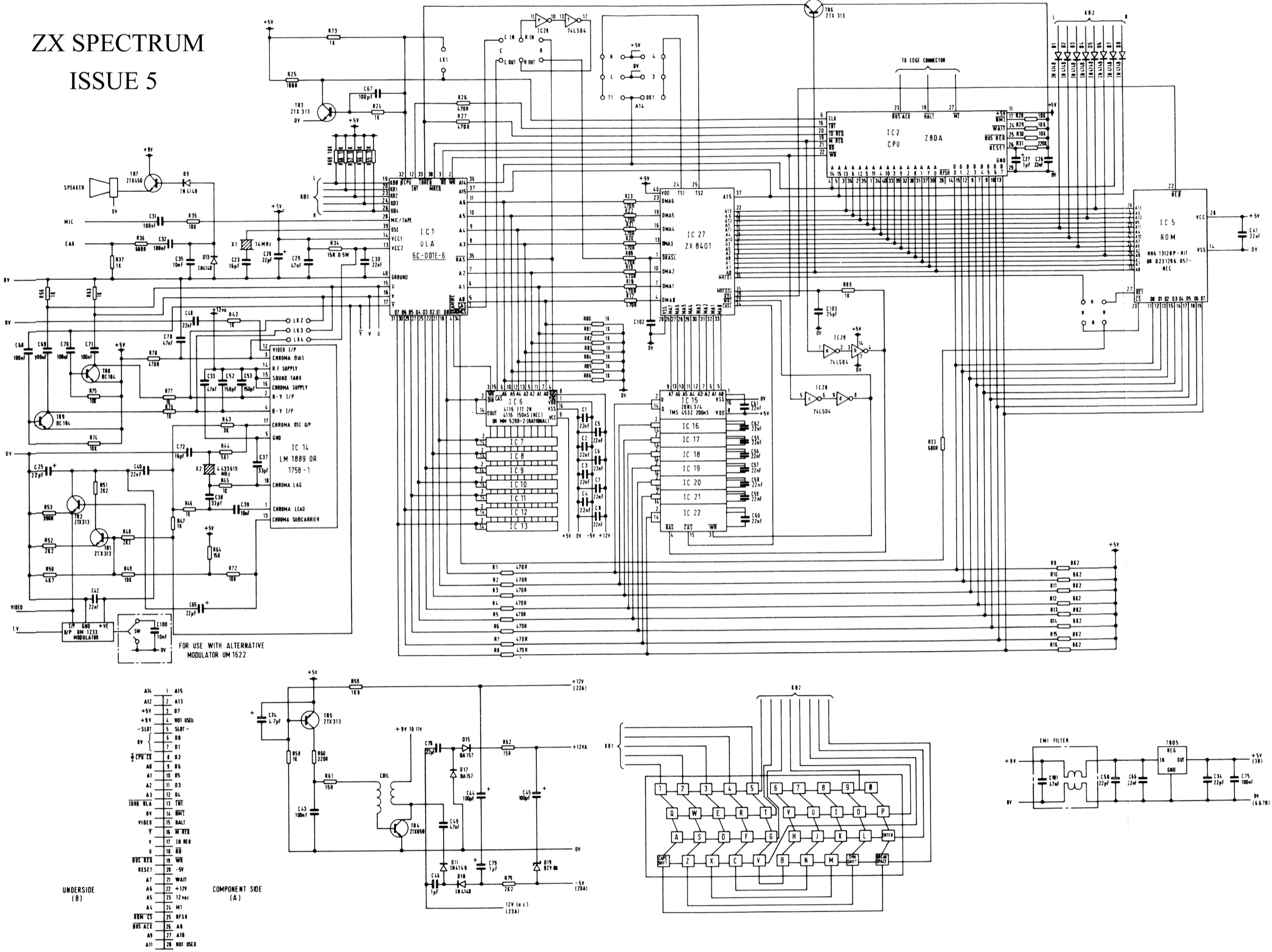
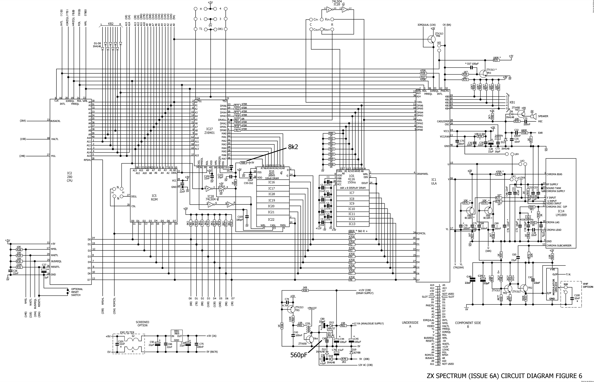
The 48K Spectrum went through several board revisions (Issue 1, 2, 3B, 4A, 6A…) that differ notably in the power supply and the video stage. The schematic archived here is the Issue 1 one: check the revision silkscreened on your board before relying on it.
Status
A manufacturer document with no explicit licence, kept for preservation (machine long out of production) — the same position as for the cabinet and arcade manuals already archived here. Source: Internet Archive.
Procedure — a dead computer, step by step ✅
What this adds
Ordered for a home computer: what kills these is its power supply, its battery, its capacitors, its socketed RAM and its keyboard — roughly in that order, and well before the CPU. → PCB diagnosis
1. The power supply — measured before it is plugged in. This is the one step not to swap around. On a machine of this age a supply does not simply stop: a 5 V regulator that fails high puts 7, 9, 12 V onto the bus and takes the RAM and the custom chips with it. Measure every rail off the machine, under a dummy load if you can, and only then plug it in. This page documents RIFA capacitors on this machine: the mains filter caps that crack, then let go in smoke on the first power-up. Replace them before you switch on, not after.
2. The battery, if it has one. Any RTC or backup cell soldered to a board is a future leak. If yours has one and it has never been changed, take it out before it takes the tracks with it. → Backup batteries
3. Capacitors. Recap is the default on these machines, not a last resort — and on the supply first, since that is what protects everything else. → Recap
4. RAM, on its sockets. These machines were built to be repaired: the RAM, and often the logic, sit in sockets. Reseat everything first — thirty years of oxide is a classic no-boot. Then swap chips: a bad RAM chip usually gives a repeatable pattern of garbage or a screen frozen at a fixed character.
5. The keyboard. A console does not have one; a computer's is a wear part. A membrane keyboard fails as whole dead rows or columns — that is the membrane, not the machine. A mechanical one wants its contacts cleaning, not replacing. Check this page: the failure mode is often documented per model.
6. Storage — tape or disk. Both often come down to the same things: a dirty head, and for tape the azimuth and a belt turned to tar. ⚠️ On the floppy side, check whether the mechanism actually has a belt before looking for one: many do, but some drives are direct drive, and hunting a belt that isn't there means stripping a drive for nothing. A machine that boots but loads nothing is a drive fault, not a logic fault — do not go looking on the board for it.
7. Video output. RF, composite, RGB or a dedicated monitor, depending on the machine (see Identification). Test with something else before you conclude: a period modulator and a modern TV disagree far more often than either is broken.
8. Still nothing. Now the logic: rails on the board, reset, clock, bus. → PCB diagnosis
Common faults
| Symptom | Likely cause | Lead |
|---|---|---|
| No / corrupt picture | ULA / lower RAM | Cool/replace ULA, substitute 4116 |
| Checkerboard at boot | lower RAM (4116) | Substitute the DRAM |
| Dead keys | keyboard membrane | Replace the membrane |
| Reset / crashes when hot | ULA / regulator | Heatsink, recap |
| Smoke (+2A/+3) | mains RIFA | Replace the RIFA |
Modernisation & mods — what to buy, how
Fragile parts: ULA, low RAM, membrane keyboard
The #1 weak point is the ULA (runs hot, dies) → a reissued modern ULA (vLA / Nebula) as a substitute. The 4116 RAM (low 16/48K bank) often fails → identify by test and substitute. The membrane keyboard cracks → a remade membrane. A modern regulated PSU is recommended.
Modern storage - DivMMC (Enjoy!) / DivIDE + ESXDOS 🟢: an SD card on the rear expansion port → instant loading (plug-and-play); Kempston SD interfaces. - Floppy +2A/+3 🟡: Gotek + FlashFloppy (internal drive connector, images from USB).
Video - The RF output is poor → a composite mod 🟡, or better an RGB mod 🟠 (RGB tapped from the ULA) → SCART then OSSC / RetroTINK / RGB2HDMI.
Reliability: light recap; clean the connectors.
⚠️ Do not host ROMs/games — method only.
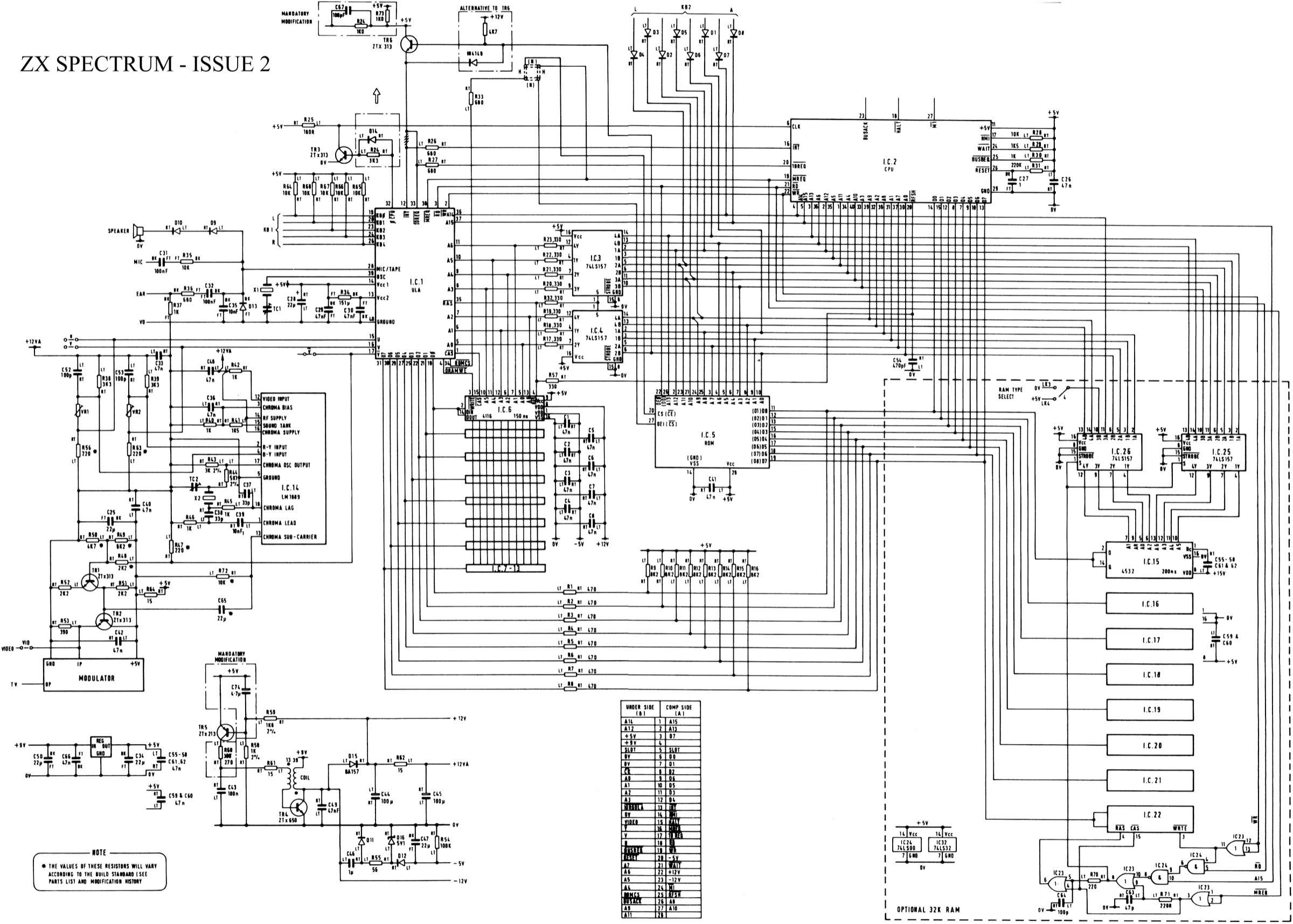
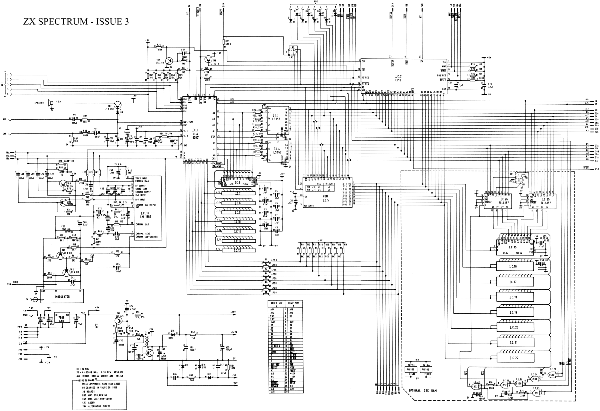
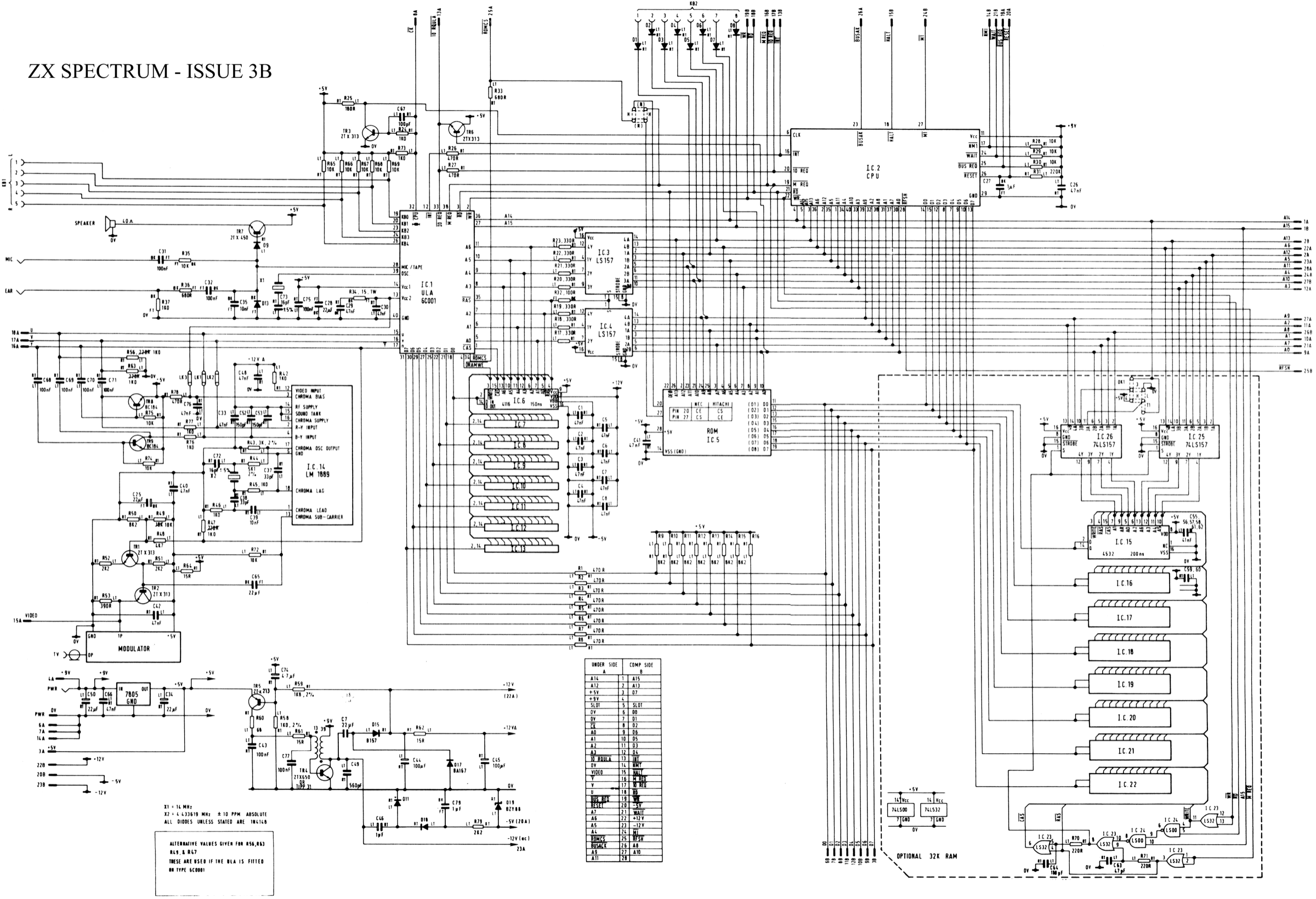
Schematics by board revision ✅
Revisions 2, 3, 3B, 4A/B, 5 and 6A — the ones missing from the Issue 1 schematic archived above. Check the revision silkscreened on the board before picking one.
Provenance
Schematics of undocumented origin in the collection they came from: no author and no licence is stated there.
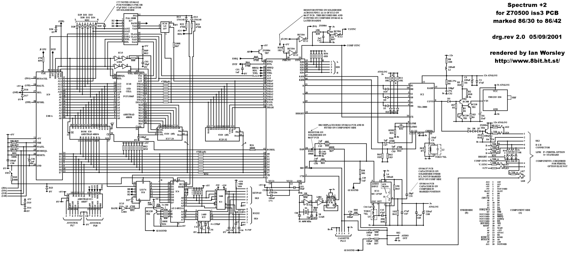
Additional schematics ✅
Plates grouped by machine. Expand to view.
Provenance
Undocumented origin in the collection: no author and no licence stated.
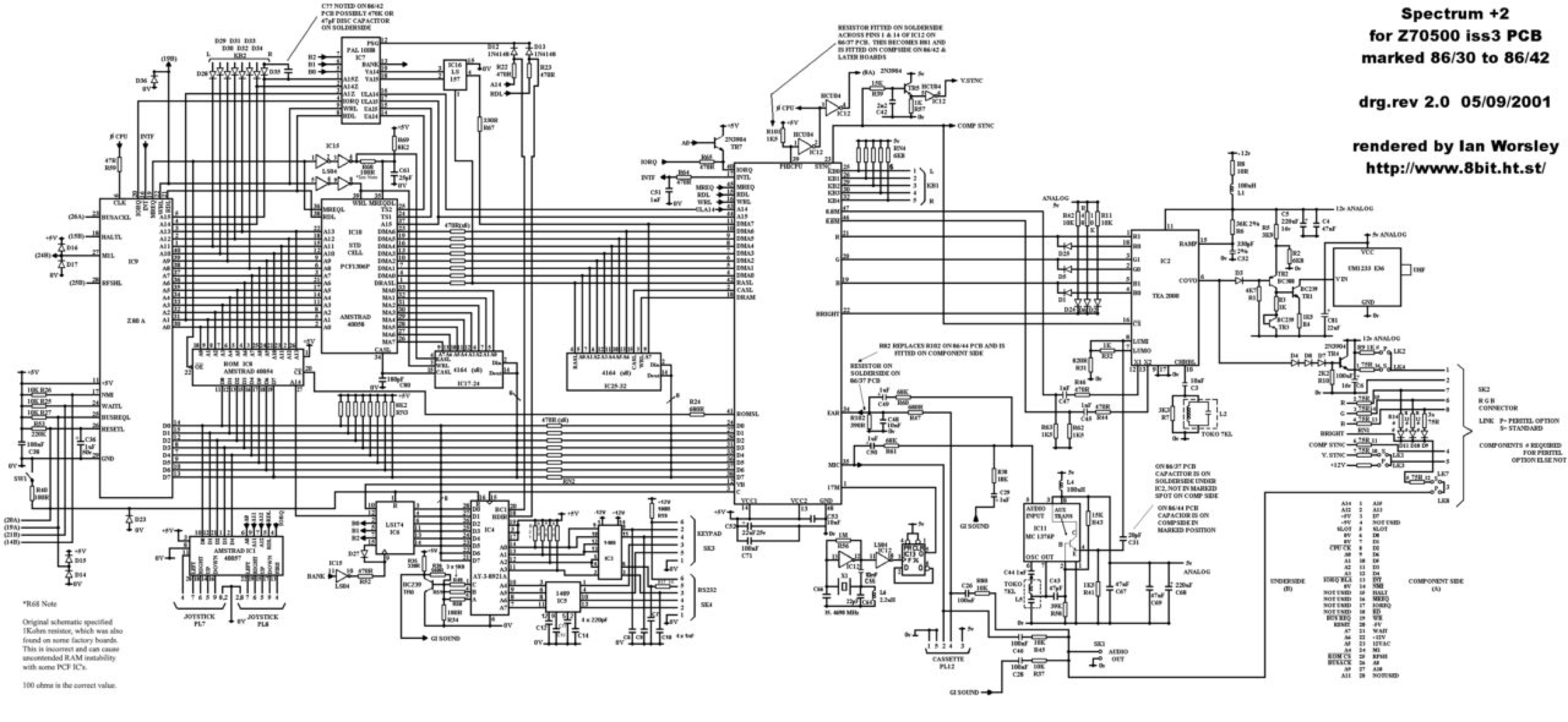
+2A / +2B / +3 — 2 planche(s)
See also
Sources & attribution
- Photo ZX Spectrum (1982) — Jzh2074, CC BY-SA 4.0, Wikimedia Commons — https://commons.wikimedia.org/wiki/File:Sinclair_ZX_Spectrum_(1982)_2.jpg
- Wikipedia — ZX Spectrum (Z80, ULA, 48/128/+2/+3 models) — CC-BY-SA — https://en.wikipedia.org/wiki/ZX_Spectrum
- Established Spectrum community knowledge (ULA, 4116 RAM, membrane, RIFA) — synthesis.
_2.jpg)
Review & corrections
How this space is used
Spotted a wrong value, an outdated procedure, a chip reference that does not match your board? Say so here, with what you observed (model, board revision, serial number, measurement). Every report is cross-checked against a source before anything changes — an unverifiable correction is published as “reported by …, not cross-checked” rather than silently applied.
Reading is open to everyone; posting requires signing in with Discord. Reports from the wiki's declared reviewers are handled first; anyone else's are read too, but go through a human before anything is changed.