JVS wiring (protocol, connectors, chaining)
JVS (JAMMA Video System, late 1990s) replaces the parallel JAMMA bus with a serial RS-485 bus: controls no longer run through the card edge but through a JVS I/O board connected to the game by a USB-type cable. The standard for Naomi, Lindbergh, Type X, System 246 cabinets and late candy cabs.
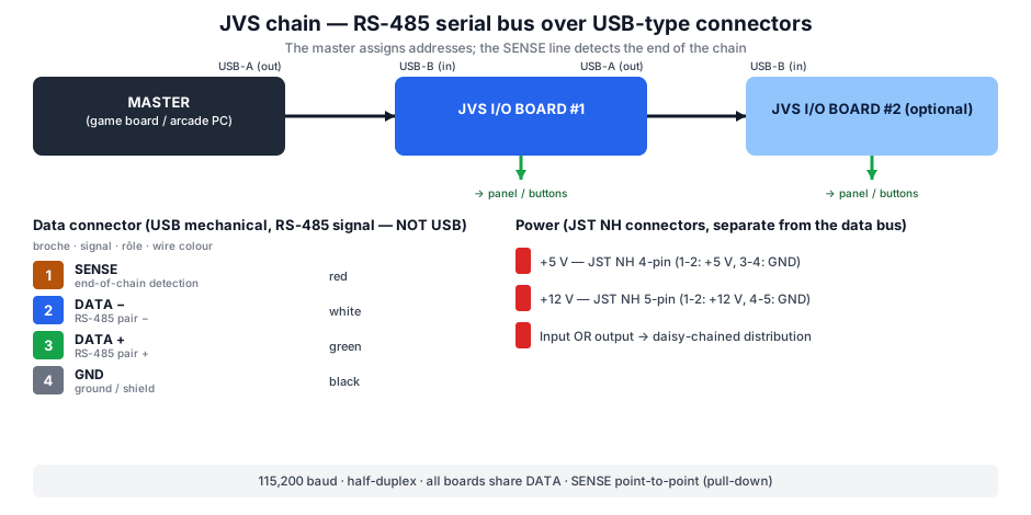
Principle: game and I/O separated
On JAMMA the game board reads the buttons directly. On JVS the game board (or the arcade PC) is a master that polls one or more I/O boards over serial; it's they that read the panel, coin mechs and drive the outputs. Benefits: standardised wiring, several boards daisy-chained, analog inputs and many outputs, longer cable runs.
The "data" connector (USB-type, but RS-485)
JVS borrows the USB connector's mechanics but is not USB: the two wires of the differential pair carry RS-485, plus a SENSE line and ground.
| Pin | Signal | Role | Wire colour |
|---|---|---|---|
| 1 | SENSE | end-of-chain detection (point-to-point, pull-down) | red |
| 2 | DATA − | RS-485 differential pair (−) | white |
| 3 | DATA + | RS-485 differential pair (+) | green |
| 4 | GND | ground / shield | black |
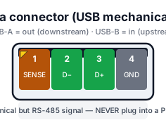
- Out = USB-A, in = USB-B. A daisy-chained I/O board has one input (B) from upstream and one output (A) to downstream.
- ⚠️ Never plug a JVS port into a PC's USB (or vice versa): mechanically it fits, electrically it's RS-485 → risk of damage.
Protocol
- RS-485, half-duplex: all boards share the same DATA pair.
- 115,200 baud, frames with a 0xE0 sync byte, address, length, data, checksum.
- Automatic addressing: at power-up the master assigns an address to each board, node by node, using the SENSE line.
- SENSE line: point-to-point between neighbouring nodes; floating when no board is downstream → that's how the master knows where the chain ends.
- The master then queries the boards (identity, capabilities: player count, buttons, analog channels, outputs) and reads the input state every frame.
Power (separate from the data bus)
The "USB" cable does not carry game power. The I/O board is powered by dedicated JST NH connectors:
| Rail | Connector | Pinout |
|---|---|---|
| +5 V | JST NH 4-pin | 1-2: +5 V · 3-4: GND |
| +12 V | JST NH 5-pin | 1-2: +12 V · 4-5: GND (3: N.C.) |
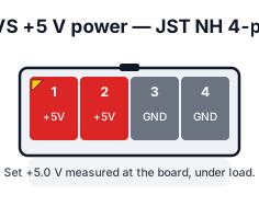
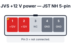
These often come in pairs (input / output) to pass +5/+12 V along to the next board in the chain.
Video & audio on JVS
- Video: comes from the game/PC, usually VGA / HD-15 (31 kHz) (Naomi, Type X, Lindbergh) — not through JVS.
- Audio: game/PC output (RCA or terminal), sometimes via an I/O board with a built-in amp (e.g. Taito JVS-AMP). JVS handles controls, not sound.
What you actually wire
- JVS cable between the game/PC (USB-A) and the I/O board (USB-B).
- +5 V / +12 V power (JST NH) to the I/O board.
- Control panel to the I/O board's input connector (see JVS I/O boards).
- Coin mechs / outputs (counters, lamps) to the dedicated terminals.
- Video/audio straight from the game/PC to monitor/amp.
→ Board details and panel pinouts: JVS I/O boards. → The historical parallel bus: JAMMA wiring.
→ Repair: PCB fault-finding · Recap.
Sources & attribution
- Arcade Otaku Wiki — JVS (RS-485, 115200 baud, SENSE, connectors) — https://wiki.arcadeotaku.com/w/JVS
- NFG Games / GameSX — JVS board connectors (4-pin USB pinout, JST power) — https://gamesx.com/wiki/doku.php?id=arcade:jvs_board_connectors
- Internal pages: JVS I/O boards · JAMMA wiring
Review & corrections
How this space is used
Spotted a wrong value, an outdated procedure, a chip reference that does not match your board? Say so here, with what you observed (model, board revision, serial number, measurement). Every report is cross-checked against a source before anything changes — an unverifiable correction is published as “reported by …, not cross-checked” rather than silently applied.
Reading is open to everyone; posting requires signing in with Discord. Reports from the wiki's declared reviewers are handled first; anyone else's are read too, but go through a human before anything is changed.