Sega Saturn
Sega's 32-bit console (1994), CD-ROM based with a multi-processor architecture famed for its complexity (two SH-2 + a slew of chips). Superb native RGB. Today, its preservation runs mostly through ODEs (Fenrir, Satiator, MODE…) that replace the CD drive.
Identification
| Field | Value |
|---|---|
| Manufacturer | Sega |
| Release | 1994 (JP), 1995 (export) |
| Generation | 5th (32-bit) |
| Models | Model 1 (oval) · Model 2 (cost-reduced) + revisions |
| Native video output | RGB (excellent), composite, S-Video |
| Region / lockout | JP / US / EU + 50/60 Hz |
| Media | CD-ROM (+ backup/RAM cartridge) |
Architecture
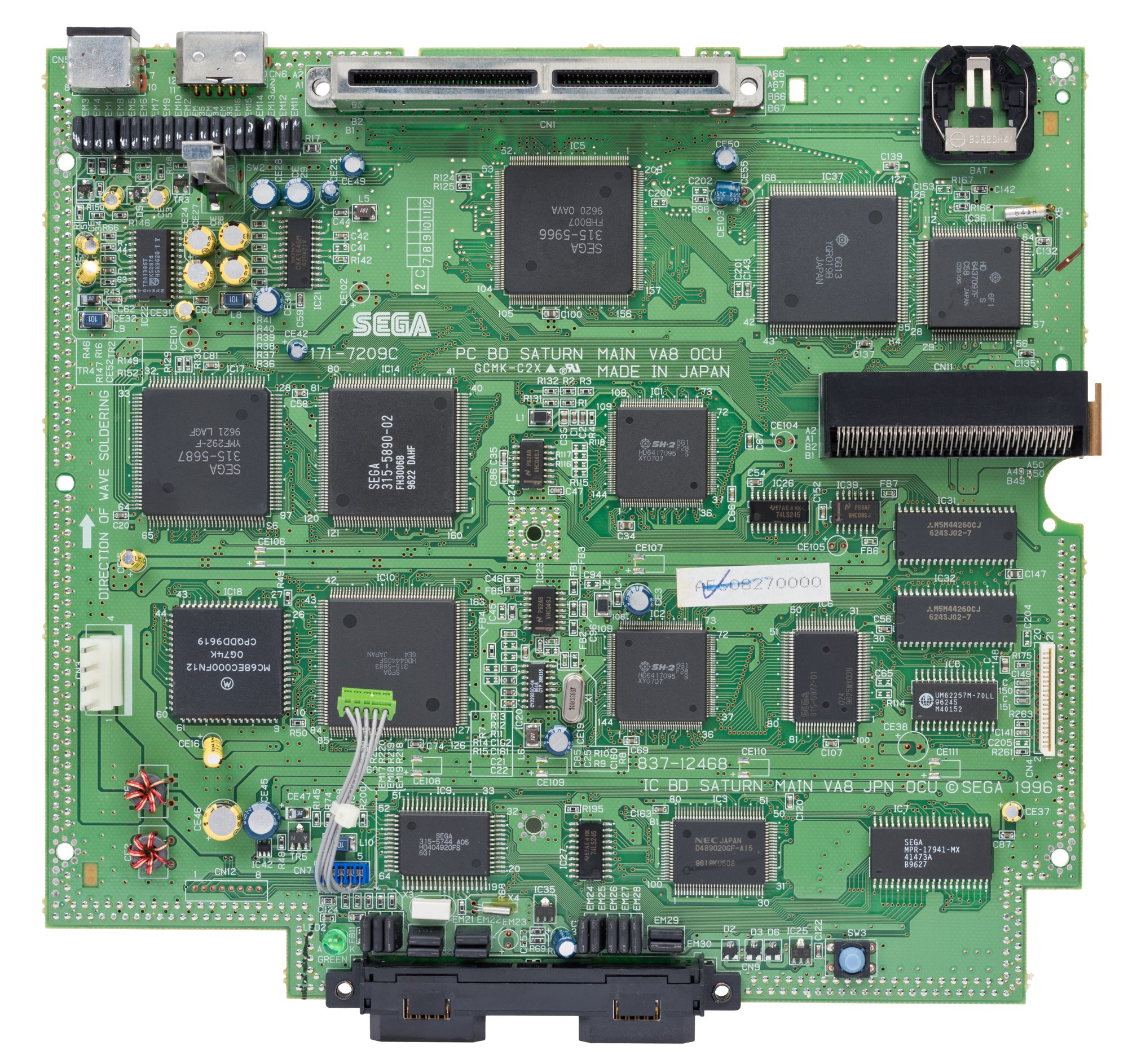
An architecture famed for its 8 processors — powerful but hard to program (especially the 3D, handled with distorted quadrilaterals rather than triangles):
| Block | Chip | Clock | Role |
|---|---|---|---|
| Main CPU ×2 | Hitachi SH-2 | 28.6 MHz | 2 cores sharing the bus (tricky sync) |
| Video 1 | VDP1 | sprites/polygons (distorted quads), framebuffer | |
| Video 2 | VDP2 | background planes, hardware rotation/scaling, priorities | |
| Sound (CPU) | Motorola 68EC000 | ~11.3 MHz | drives the sound |
| Sound (DSP) | Yamaha SCSP (YMF292) | 32 voices PCM/FM | |
| System | SMPC (system control, MCU) | power, reset, controllers, RTC | |
| CD | dedicated Hitachi SH-1 | drives the CD-ROM drive | |
| Coprocessor | SCU DSP (in the SCU) | geometry/DMA | |
| Memory | 2 MB work (1 MB "high" SDRAM + 1 MB "low" DRAM) · 1.5 MB VRAM · 512 KB sound · 512 KB CD buffer | ||
| Misc | CR2032 battery (clock/save) |
The Saturn is above all the 2D king (VDP2: planes, rotation/scaling, rich priorities) — hence its cult status for shmups and fighters (2D ports are often better than on the PS1).
Controllers & peripherals
- 3D Control Pad (Model 2, analog + triggers): built for NiGHTS, it foreshadows modern analog pads.
- 6Player multitap (6-player games, e.g. Saturn Bomberman), Virtua Stick (arcade), Twin Stick (Virtual-On), Virtua Gun/Stunner (light gun, CRT), a keyboard and a mouse.
- NetLink: an official modem (online play + web browser), US/JP — a dead service, sought-after hardware.
Common faults
| Symptom | Likely cause | Lead |
|---|---|---|
| Won't read CDs | Worn laser / optical block | Adjust/replace the laser, or ODE |
| Clock / saves lost | Flat CR2032 battery | Replace the battery |
| Corrosion / degraded sound-video | Capacitors | Targeted recap |
| Backup cartridge not recognised | Cartridge slot contacts | Cleaning |
| No image | Power, contacts, VDP | Diagnosis |
| Colour smearing | Failed EMI filters — a known Saturn fault | Replace the EMI filters |
| A first-print game refuses to run (Space Harrier, OutRun) | Console is VA10 or later (68000+SCSP merged) | It isn't the disc: see Revisions |
Colour smearing: the EMI filters
The EMI filters on the Saturn are known to go bad. Typical symptom: colour smearing on screen.
Two repair routes:
- Buy compatible EMI filters, 3-pin, 100 pF;
- or borrow the ones from the nearby communication port — in which case bridge pads 1 and 3 at the spot you took them from.
(Process and images: Leon Kiriliuk, via ConsoleMods, CC-BY-SA. The source page writes both "EFI" and "EMI"; these are EMI filters.)
Step-by-step disassembly procedures ✅
6 procedures transcribed from the iFixit guides, with difficulty and estimated time.
| Procedure | Difficulty | Time |
|---|---|---|
| Sega Saturn Battery Replacement | Easy | 30 seconds |
| Sega Saturn Case Replacement | Moderate | 4 minutes |
| Sega Saturn Disc Reader Replacement | Moderate | 10 minutes |
| Sega Saturn Motherboard Replacement | Moderate | 30 minutes |
| Sega Saturn Power Button Replacement | Moderate | 10 minutes |
| Sega Saturn Power Supply Replacement | Moderate | 10 minutes |
Sega Saturn Battery Replacement
The Sega Saturn is a home video game console which contains a battery that has an average lifespan of 1-2 years. A healthy battery within this console is necessary for the Sega Saturn to work properly. If your console isn’t turning on, or if it only turns on briefly before turning off again, you are probably experiencing an issue relating to its battery. This repair guide will demonstrate and explain how to properly disassemble the Sega Saturn and replace its battery in order to restore it back to its functioning condition. Battery replacement will likely resolve the issues described above. There are no specific or special skills needed to complete this repair, and there is nothing unusual about this repair process. Please use a new battery when replacing your old one to delay further battery repairs.
- Press on the plastic lever on the back of the Sega Saturn to pop open the battery slot.
- Push up the edge of the battery with the iFixit opening tool to get the battery out of its socket.
- Use the ESD safe tweezers to pull the battery out of its slot.
Sega Saturn Case Replacement
This guide will walk you through safely removing the battery and outer case of the Sega Saturn, either for replacing the case or gaining access to other internal parts. If your case is physically damaged, you can use this guide to completely replace the outer case. However, if you find your case is structurally sound but has yellowed or become discolored, you can remove the case and clean it chemically to restore it’s original color.
- Press on the plastic lever on the back of the Sega Saturn to pop open the battery slot.
- Push up the edge of the battery with the iFixit opening tool to get the battery out of its socket.
- Use the ESD safe tweezers to pull the battery out of its slot.
- Remove the five black 13.5mm JIS#1 screws on the bottom of the device. One might be hidden by a sticker.
- Flip the device over so it rests right side up.
- Lift gently across the seam of the Sega Saturn. If parts get stuck, a light shake or prying with the iFixit opening tool should free it up. Do not use any brute force, as this can damage the case so it doesn't close again.
Sega Saturn Disc Reader Replacement
If your Sega Saturn fails to read discs properly, use this guide to replace the disc reader. The disc reader transmits data from a disc to the Saturn itself. A misaligned or damaged disc reader will stop the disc from spinning or cause the Saturn to display a “Drive Empty” message. Before using this guide, clean the disk reader lens with a cotton ball and rubbing alcohol, as a dirty optical drive may be the cause of a disc reading failure.
- Press on the plastic lever on the back of the Sega Saturn to pop open the battery slot.
- Push up the edge of the battery with the iFixit opening tool to get the battery out of its socket.
- Use the ESD safe tweezers to pull the battery out of its slot.
- Remove the five black 13.5mm JIS#1 screws on the bottom of the device. One might be hidden by a sticker.
- Flip the device over so it rests right side up.
- Lift gently across the seam of the Sega Saturn. If parts get stuck, a light shake or prying with the iFixit opening tool should free it up. Do not use any brute force, as this can damage the case so it doesn't close again.
- Do not touch the laser reader, as smudges have been reported to ruin it.
- Pull firmly on the ribbon cable from the end on the motherboard.
- Don't worry about pulling it out of its socket; it can be plugged back in.
- Pry the second cable out of its socket on the disk reader with the iFixit opening tool or ESD safe tweezers. When the lip of the cable gets enough distance out of the socket, it can be wiggled free.
- Lift the laser reader slowly out of its slot hosted by these four pins. There is a screw underneath with a cable attached to the motherboard.
- Remove the metallic 12.2mm JIS #1 screw. This will need additional hands in reverse to hold the disk reader steady.
- Remove the yellow tape on the reader strip and gently remove the disc reader without touching the laser reader.
Sega Saturn Motherboard Replacement
This guide will help you replace the motherboard of a Sega Saturn. First: before disassembling, please get the detailed tools together. There are some plastic sockets that are just really bad, so having the right screw or tool for the job can save you a lot of time. Second: Be careful removing the Power Supply Board, the pins that hold it in place connect right to the motherboard, and breaking can lead to replacing two parts instead of one. Third: Do NOT touch the disc reader’s laser (Step 12 for picture). There have been reports of smudging ruining it and making it require replacement, so just avoid touching that area. Other than that, just read each step through before doing it and this repair will be a fun project.
- Press on the plastic lever on the back of the Sega Saturn to pop open the battery slot.
- Push up the edge of the battery with the iFixit opening tool to get the battery out of its socket.
- Use the ESD safe tweezers to pull the battery out of its slot.
- Remove the five black 13.5mm JIS#1 screws on the bottom of the device. One might be hidden by a sticker.
- Flip the device over so it rests right side up.
- Lift gently across the seam of the Sega Saturn. If parts get stuck, a light shake or prying with the iFixit opening tool should free it up. Do not use any brute force, as this can damage the case so it doesn't close again.
- Unplug the power button plug on the power supply board. Use the iFixit opening tool if necessary.
- Remove the two black 11.4mm standoff screws on the back of the Sega Saturn holding the power socket in place. These screws are tight and easily stripped, so it's suggested to use a standoff screw head.
- Remove the metallic 12.3mm JIS#1 screw holding down the power supply board.
- Lift the power supply board out of its socket, minding the pins that connect it to the motherboard. Some force will be required, but be careful when lifting or shaking the power supply board out.
- Remove the metallic 13.7mm JIS#1 screw on the right of the Power Button.
- Remove the metallic 12.4mm JIS#1 screw on the left of the Power Button.
- Push the plastic resting tray’s pin located here.
- Remove the plastic resting tray to free the wire between the power supply board and the button.
- Remove the power button when the wire is free.
- Do not touch the laser reader, as smudges have been reported to ruin it.
- Pull firmly on the ribbon cable from the end on the motherboard.
- Don't worry about pulling it out of its socket; it can be plugged back in.
- Pry the second cable out of its socket on the disk reader with the iFixit opening tool or ESD safe tweezers. When the lip of the cable gets enough distance out of the socket, it can be wiggled free.
- Lift the laser reader slowly out of its slot hosted by these four pins. There is a screw underneath with a cable attached to the motherboard.
- Remove the metallic 12.2mm JIS #1 screw. This will need additional hands in reverse to hold the disk reader steady.
- Remove the yellow tape on the reader strip and gently remove the disc reader without touching the laser reader.
- Remove the four metallic 15.5mm JIS#1 screws from the Motherboard Frame.
- Remove the four metallic 13.6mm JIS#1 screws from the Motherboard Frame.
- Remove the metallic 12.3mm JIS#1 screw from the Motherboard Frame.
- Lift the motherboard frame out carefully because of the delicate parts on the motherboard.
- You do not need to remove the plastic Power LED Reflector. If it does pop out, don't worry, it can be pushed back into its socket. It may require rotation to fit the case when closed.
- Lift the motherboard away from the controller sockets in the front of the device while keeping your hands on the edges of the board
- Once the back of the motherboard is above the back of the case, lift backwards to pull the cables out of their sockets to free the motherboard.
Sega Saturn Power Button Replacement
Follow this guide if you want to replace the power button on your Sega Saturn. This guide is almost a carbon copy of replacing the Power Supply Board with a few extra steps. So, before you begin disassembling: I advise getting the detailed tools together, as the screws on the Power Supply Board have bad plastic sockets and a Standoff screwdriver really helps get those rigid screws in and out. The toughest part of this guide will be removing the Power Supply Board, as the last thing holding it in place are pins directly from the motherboard. Breaking those can lead to replacing two parts of the Sega Saturn, and it doesn’t help that it takes a good amount of force to unplug the pins either… Just take your time on that step and this repair should go fine.
- Press on the plastic lever on the back of the Sega Saturn to pop open the battery slot.
- Push up the edge of the battery with the iFixit opening tool to get the battery out of its socket.
- Use the ESD safe tweezers to pull the battery out of its slot.
- Remove the five black 13.5mm JIS#1 screws on the bottom of the device. One might be hidden by a sticker.
- Flip the device over so it rests right side up.
- Lift gently across the seam of the Sega Saturn. If parts get stuck, a light shake or prying with the iFixit opening tool should free it up. Do not use any brute force, as this can damage the case so it doesn't close again.
- Unplug the power button plug on the power supply board. Use the iFixit opening tool if necessary.
- Remove the two black 11.4mm standoff screws on the back of the Sega Saturn holding the power socket in place. These screws are tight and easily stripped, so it's suggested to use a standoff screw head.
- Remove the metallic 12.3mm JIS#1 screw holding down the power supply board.
- Lift the power supply board out of its socket, minding the pins that connect it to the motherboard. Some force will be required, but be careful when lifting or shaking the power supply board out.
- Remove the metallic 13.7mm JIS#1 screw on the right of the Power Button.
- Remove the metallic 12.4mm JIS#1 screw on the left of the Power Button.
- Push the plastic resting tray’s pin located here.
- Remove the plastic resting tray to free the wire between the power supply board and the button.
- Remove the power button when the wire is free.
Sega Saturn Power Supply Replacement
Follow this guide if you need to replace the power supply of your Sega Saturn. Before you begin disassembling, I advise getting the detailed tools together, as the screws have bad plastic sockets, so having the Standoff screwdriver really helps get those rigid screws in and out. The toughest part of this guide will be finally removing the Power Supply Board, as the last thing holding it in place are pins directly from the motherboard. Breaking those can lead to replacing two parts of the Sega Saturn, and it doesn’t help that it takes a good amount of force to unplug the pins either… Just take your time on that step and this repair should be fine.
- Press on the plastic lever on the back of the Sega Saturn to pop open the battery slot.
- Push up the edge of the battery with the iFixit opening tool to get the battery out of its socket.
- Use the ESD safe tweezers to pull the battery out of its slot.
- Remove the five black 13.5mm JIS#1 screws on the bottom of the device. One might be hidden by a sticker.
- Flip the device over so it rests right side up.
- Lift gently across the seam of the Sega Saturn. If parts get stuck, a light shake or prying with the iFixit opening tool should free it up. Do not use any brute force, as this can damage the case so it doesn't close again.
- Unplug the power button plug on the power supply board. Use the iFixit opening tool if necessary.
- Remove the two black 11.4mm standoff screws on the back of the Sega Saturn holding the power socket in place. These screws are tight and easily stripped, so it's suggested to use a standoff screw head.
- Remove the metallic 12.3mm JIS#1 screw holding down the power supply board.
- Lift the power supply board out of its socket, minding the pins that connect it to the motherboard. Some force will be required, but be careful when lifting or shaking the power supply board out.
Source, licence and scope
iFixit guides, under Creative Commons BY-NC-SA — attribution, non-commercial, share-alike. Only the text is reproduced; the step photos stay on iFixit. ⚠️ These guides target the model named in the title: on another revision, the screws and the order of removal may differ.
Procedure — a dead console, step by step ✅
What this adds
Ordered for a console, not for an arcade board: what kills these is almost never the CPU. It is, in real order, the power supply, the capacitors, the drive or the cartridge slot, and only then the logic. → PCB diagnosis
1. The power supply. Two cases, depending on the machine. External brick: ⚠️ read the marking on the machine, next to the socket, and check the adapter against it — voltage and polarity. A centre-negative machine fed centre-positive loses its fuse, sometimes its regulator; do not trust a third-party label or a generic tip. Internal supply (the machine plugs straight into the wall): mains is inside the shell. Unplug, wait, and confirm the large capacitors are discharged before touching the board. Either way, measure under load: a failing supply holds its voltage until it is asked for current.
2. The fuse. Many of these machines have one right behind the socket — it is the part designed to die. Test it in continuity, out of circuit. A fuse that blows again is a short, not a fuse problem.
3. Capacitors. On most machines of this age this is the default suspect rather than a last resort — leaking SMD electrolytics eat the tracks underneath before they give any other sign. ⚠️ Not all of them are like that: some carry very few and are not recapped on principle. Read what this page says about it before reaching for the iron. → Recap
4. The drive. On this machine it is the dominant failure point. In order: does the tray move, does the disc spin, is the lens clean (cotton bud, isopropyl alcohol, no pressure), do the rails slide freely. A laser that no longer reads gets replaced; the gain pot is not something to tweak blind — that is the move that finishes off a laser that was still good.
5. Video output. Isolate the machine from the display: another cable, another TV, another input. A sizeable share of "dead consoles" are a dead cable, or a display that will not lock onto what this machine outputs — see the video section of this page for what that is.
6. Still nothing. Now, and only now, the logic: rails on the board, reset, clock, bus. → PCB diagnosis
The cartridge slot (RAM, backup, modchip)
Under the Saturn, a cartridge slot serves three distinct purposes:
- RAM expansion cartridge: some games require it (otherwise they don't run / crash). Two capacities: 1 MB and 4 MB. E.g. X-Men vs. Street Fighter, Marvel Super Heroes, Vampire Savior → 4 MB; King of Fighters '95 used a dedicated ROM cartridge.
- Save cartridge (backup RAM): extra memory to store saves (the internal battery-backed RAM is small and volatile if the battery dies).
- "Action" cartridge / Pseudo Saturn Kai: free firmware loaded from a cartridge (a flashed Action Replay type) that brings region-free + import + save reading — no soldering.
Combining the functions
Modern cartridges combine RAM expansion + backup + Pseudo Saturn Kai, handy to cover all needs with a single module.
Region, disc security & region-free
- Region: JP / US / EU + 50/60 Hz.
- Disc security: the Saturn CD carries a security ring (an edge pattern) that burners cannot reproduce → a raw CD-R won't boot without help. Routes: a soldered modchip (injects the "disc OK"), the old swap trick, or — the cleanest — an ODE (Fenrir/Satiator) that removes the drive.
- Region-free: Pseudo Saturn Kai (cartridge, no soldering), a region-free BIOS, or a modchip. The 50/60 Hz switch completes it for full screen/speed.
Board revisions — identifying yours ✅
There are only two models of Saturn, but around fifteen motherboard revisions. Both models are functionally identical with the same dimensions; the rear port arrangement is identical: a 10-pin mini-DIN for AV out, a rectangular serial and MIDI port, and the power connector — a non-polarized IEC C8 on all consoles except US ones. Also at the rear, a panel conceals the CR2032 battery slot (which powers both the real-time clock and the save memory), the expansion slot for MPEG/Video CD cards, and — on earlier models — a reset button for the internal memory.
THE method: the 3rd digit of the serial number
From the VA1 onwards, the third digit of the serial number directly gives the board revision:
| 3rd digit | Revision | 3rd digit | Revision |
|---|---|---|---|
| 1 | VA1 | 8 | VA8 OCU |
| 2 | VA SG "VA2" / "VA4" | 9 | VA9 |
| 3 | VA SD "VA3" / "VA5" | A | VA10 OCU |
| 4 | VA SG "VA4" (Model 2) | B | VA11 |
| 5 | VA SD "VA5" (Model 2) | D | VA13 |
| 6 | VA6 SG | F | VA15 |
| 7 | VA7 SD |
Visual identification once opened (5 screws underneath)
This is the modchip guides' method, and it is still the quickest. The "ribbon cable" refers to the white flat cable connecting the CD board to the motherboard; the IC pin count refers to a chip soldered onto the CD board.
| Buttons | Ribbon | IC on the CD board | Conclusion |
|---|---|---|---|
| Oval | 20-pin | — | Model 1 |
| Oval | 21-pin | 64-pin | Model 2 |
| Round | 21-pin | 64-pin | Model 2 |
| Round | 21-pin | 32-pin | Model 2 |
| Round | 21-pin | no IC | Model 2, the so-called Sanyo board |
From the outside it is nearly impossible
The Model 1 is recognisable by its oval buttons surrounded by a glossy bezel (matte on the V-Saturn), and it is the only main model with a disc activity LED (labelled "Access"). But determining the board revision without opening up is impossible — other than via the serial number above.
Model 1 (1994-1996)
| Revision | What you need to know | P/N |
|---|---|---|
| VA0 (1994-1995) | Initial revision, all regions. The most complex internal construction of any Saturn: the power supply is mounted inside the top case, as are the two LEDs, reset button and disc door pinswitch — all connected by wire harnesses. The CD hardware (SH-1, OCU, CD buffer RAM) sits on a separate daughterboard (the "SH1 Board" in service documentation), which also carries the expansion slot and the 20-pin drive connector. BIOS v1.00. "T"-shaped power connector at the rear (extra screw at the lower left on Japanese consoles); US units have a unique D-shaped IEC connector. | 171-6874D (JP) · 171-6962B (US) · 171-6963B (PAL) |
| VA0.5 (1995) | Almost identical to the VA0, but relocates R133 (SSCK pull-up) and R134 (SRXD pull-up) to the underside of the board. | 171-6874E (JP) |
| VA0.8 (1995) | Practically identical to the VA0.5. Mainly found in Taiwanese-built US consoles. | 171-6962C (US) |
| VA1 (1995) | Much greater consolidation: the power supply connects directly to the motherboard (5-pin header) and lives in the bottom case; SH1 Board, rear expansion slot and disc door switch integrated. To make room for the CD hardware, the BIOS ROM and save RAM move to the underside. Controller ports, LEDs and reset button sit on a separate PCB joined by a short flex cable. US consoles switch to a polarized IEC C8. Last revision with SMD electrolytic capacitors and last with the 20-pin drive connector. | 171-7006C (NTSC) · 171-7069B (PAL) |
| VA SG "VA2" (1995-1996) | Like the VA1 but uses SGRAM. First revision with through-hole electrolytics throughout and first with the 21-pin drive connector. Not found in PAL consoles. | 171-7128B |
| VA SD "VA3" (1995-1996) | Mostly identical to the VA SG but uses SDRAM. Not found in US consoles. Last to use a 5-pin power supply across all regions. | 171-7130B (NTSC) · 171-7131A (PAL) |
Model 2 (1996-1998)
The Model 2 drops the disc activity LED and the memory reset button near the battery holder; the VA SG/VA SD boards carry over under the names "VA4" and "VA5".
| Revision | What you need to know | P/N |
|---|---|---|
| VA6 SG (1996) | Controller port board fully integrated into the motherboard. First 4-pin power header (NTSC) — the 9 V DC output is removed as it is unnecessary on NTSC consoles. SH-1 and OCU combined into the 315-5962 (Hitachi YGR022) (CD buffer RAM still discrete). ⭐ First to use the Cypress CY2292SC PLL, an off-the-shelf component which is more reliable than the original Hitachi PLL. SGRAM, NTSC only. | 171-7207A |
| VA7 SD (1996) | Almost identical to the VA6 but uses SDRAM. PAL boards retain all five power header pins: 9 V DC is needed on the AV out for SCART aspect ratio autoswitching. | 171-7208C |
| VA8 OCU (1996) | Like the VA6 but back to separate SH-1 and OCU chips (hence "OCU"). The official reason is unknown — possibly to use up excess parts inventory, as it was produced alongside the VA6 and VA7. SGRAM, NTSC only. | 171-7209C |
| VA9 (1996) | The only revision using the same layout for both NTSC and PAL. Separate SH-1 and OCU (the last to do so). ⚠️ Went back to the original Hitachi PLL. SDRAM. Found only in PAL, Hi-Saturn and V-Saturn consoles — the only known board revision for Model 2 Hi-Saturns. | 171-7291B · 171-7291C |
| VA10 OCU (1996-1997) | 68000 sound CPU and SCSP now integrated into a single IC, the 315-5965 (Yamaha YMF713-S) → ⚠️ compatibility problems (see box). Last revision with SGRAM. Back to the 315-5962 CD chip. Some VA10s carry a small "bodge" board near the VDP1 (two 74HC161s and a 74HC00): a clock divider providing an 8.4 MHz signal fed into the PLL. NTSC only. | 171-7287C |
| VA11 (1996-1997) | Largely identical to the VA10, but the audio amplifier (upper left, near the AV port) is TSOP rather than SOIC. Some boards also have the bodged clock PCB. | — |
| VA13 (1997) | Final revision for consoles outside Japan and NTSC Asia. Mostly the VA11 but incorporates the "bodge" board. First revision found in "Skeleton" Saturns (the 1998 Special Campaign Original giveaway). | 171-7288D (NTSC) · 171-7455D (PAL) |
| VA15 (1997-1998) | The final Saturn revision overall. Both SH-2 CPUs combined into a single chip, the 315-6018 (Hitachi HD6417098). Japanese and NTSC Asian consoles only, including most Skeleton Model 2s. | 171-7462B |
VA10 and later: known game incompatibilities
Merging the 68000 and the SCSP into the 315-5965 introduced 68000 code issues, causing compatibility problems with several games — notably Space Harrier and OutRun. Sega had to issue a revised print run of these titles, compatible with VA10 and newer consoles. A first-print copy may therefore refuse to run on a late Saturn: the problem is the console, not the disc.
The PLL: the component that decides repairability
Revisions VA0 → VA SD, plus the VA9, use the 315-5746 (Hitachi HD49422) PLL — an IC that is currently irreplaceable and very sensitive to heat. Take extreme care when desoldering nearby: a cooked PLL condemns the board.
Revisions VA6, VA7, VA8, VA10 and later use the Cypress CY2292SC, an off-the-shelf, more reliable and replaceable part.
PAL VA0: the 50/60 Hz mod is half done for you
PAL VA0s have an unused footprint near the battery holder originally intended for a 50/60 Hz switch, which greatly facilitates region mods. (Source: ConsoleMods, CC-BY-SA.)
Rebadges and one oddity
Both models were also sold in Japan by Hitachi (Hi-Saturn) and JVC/Victor (V-Saturn): these are simple rebadges, largely identical to a standard Saturn except for the BIOS splash screen.
Separately, the Game & Car Navi Hi-Saturn (1995) is considerably smaller and slimmer (thanks to an external 12 V supply) and was intended for use in a vehicle — with a GPS receiver input, map CDs for navigation with an optional LCD screen, a mono AV input, a TV tuner connector, and even microphone inputs with audio effects for karaoke. It is functionally identical to a regular Saturn and compatible with all games and accessories — but ⚠️ it lacks RGB output despite having the same mini-DIN. Fixable with a simple RGB mod.
Recap
The Saturn has a huge number of revisions (see above), plus many PSUs and CD drives, each with its own list. There is no single BOM — identify your revision (the 171-… reference above, or the 3rd digit of the serial) and follow the matching list.
Where the SMD → through-hole switch happens
The VA1 is the last motherboard with SMD electrolytics; the VA SG "VA2" is the first entirely through-hole. This completely changes the nature of the recap (tooling, risk of lifting pads): check it before ordering a kit. Source (per revision, with CXX references): Console5 TechWiki
(Saturn).
Popular mods — what to buy, where, procedures
Drive type (crucial for the ODE)
Two mechanisms: a "round" drive (round ribbon) → Rhea; a "flat" drive (flat ribbon) → Phoebe. Fenrir and Satiator cover both via adapters. Check your model before buying. Procedures from ConsoleMods (CC-BY-SA). Soldering: 🟢 none · 🟡 · 🟠 · 🔴.
Games on SD — ODE (replace the CD drive)
- Fenrir / Satiator / Rhea-Phoebe (by MODE/Terraonion et al.) — replace the drive: games from an SD card, plugging into the drive connector (little or no soldering per kit). → Saturn ODE page.
Region-free & backups — no-solder first
- Pseudo Saturn Kai: free software launched from a cartridge (flashable Action Replay/RAM cart, or an ODE) → region-free + imports/backups, zero soldering 🟢. The simplest route.
- Region-Free BIOS Replacement: swap the BIOS chip for a region-free version (soldering 🟠) — a clean permanent fix; often paired with a 50/60 Hz switch.
Video
- Native RGB: nothing to solder, just the right RGB SCART cable → superb stock.
Saves, RAM, reliability
- The CR2032 backup battery (internal memory) dies → Battery Replacement; or the FRAM Mod (battery-free saves). Clean the cartridge connector (a crash source).
- RAM expansion cartridge (1 MB / 4 MB): required by some games (KOF'95/97, X-Men vs SF, Vampire Savior…) — don't forget it. Modern Gamer's Cartridges bundle RAM + backup.
- Preventive recap (per revision/condition), Digital Audio (SPDIF), In-Game Reset (IGR).
Emulation
- Long very hard (8-chip architecture); now decent: Mednafen/Beetle Saturn, Kronos, SSF, Ares.
Manual (archived)
- 📘 Sega Saturn service manual (PAL, 013-1, 1995) (PDF) — Source: Sega Retro, archived locally for preservation.
Photos / assets
(To add: Model 1 vs 2 board, laser block, battery, RGB multi-out.)
Advanced repair
Backup battery (CR2032) + optical drive (laser/belt) + recap. Methods: Backup batteries · ODE (optical drive) · Recap · PCB fault-finding.
Archived manufacturer documentation ✅
Manufacturer documentation archived locally. ⚠️ These are owner's and reference manuals, not service manuals: they give the specifications, the connectors and the expected behaviour, but not the schematics or troubleshooting voltages.
Status
Manufacturer documents with no explicit licence, kept for preservation (machines out of production for decades).
Sources & attribution
- Wikipedia — Sega Saturn — CC-BY-SA — https://en.wikipedia.org/wiki/Sega_Saturn
- ConsoleMods Wiki — Saturn Model Differences — CC-BY-SA — the ~15 revisions VA0→VA15, 3rd serial digit = revision, SMD→through-hole switch at the VA SG, 20 vs 21-pin drive connectors, irreplaceable heat-sensitive Hitachi 315-5746 PLL vs Cypress CY2292SC, VA10+ incompatibilities (Space Harrier, OutRun), the PAL VA0 50/60 Hz footprint, Hi-Saturn/V-Saturn rebadges and the Game & Car Navi — https://consolemods.org/wiki/Saturn:Saturn_Model_Differences
- ConsoleMods Wiki — General Troubleshooting — CC-BY-SA — failing EMI filters → colour smearing, replacement with 3-pin 100 pF parts or borrowing from the communication port with pads 1 and 3 bridged — process and images by Leon Kiriliuk — https://consolemods.org/wiki/Saturn:General_Troubleshooting
- ConsoleMods Wiki — Modchips — CC-BY-SA — visual identification key once opened (oval/round buttons, 20/21-pin ribbon, 64/32-pin or no IC "Sanyo board") — taken from a web archive of segastyle.com — https://consolemods.org/wiki/Saturn:Modchips
What we did not transcribe (and why)
The ConsoleMods pages Region Information, Pseudo Saturn Kai, Battery Replacement, Rechargeable Battery Mod, Power Supply Fuse and RAM and Cheat Cartridges are empty to this day (red links) — our region and cartridge-slot sections therefore rest on our existing sources, with nothing invented.
Image:
-
saturn-board.jpg— Evan Amos (Vanamo Media), public domain — https://commons.wikimedia.org/wiki/File:Sega-Saturn-Motherboard.jpg

Review & corrections
How this space is used
Spotted a wrong value, an outdated procedure, a chip reference that does not match your board? Say so here, with what you observed (model, board revision, serial number, measurement). Every report is cross-checked against a source before anything changes — an unverifiable correction is published as “reported by …, not cross-checked” rather than silently applied.
Reading is open to everyone; posting requires signing in with Discord. Reports from the wiki's declared reviewers are handled first; anyone else's are read too, but go through a human before anything is changed.