Philips VG-5000
A 1984 French micro built around a Z80 and an EF9345 — Thomson's video controller, also found on the Alice 32/90 and, in a variant, on the Videopac+ G7400.
Identification
| Field | Value |
|---|---|
| Manufacturer | Philips |
| Year | 1984 |
| CPU | Z80 @ 4 MHz |
| Video | EF9345 (SGS-Thomson) |
| RAM | 24 KB in three 8 KB D4168C — of which 8 KB for the video processor |
| Rebadges | Radiola VG5000 and Schneider VG5000 |
Expected clock — measurement table ✅
| Component | Frequency |
|---|---|
| Z80 | 4 MHz |
Incomplete emulation — what that implies
The MAME driver carries the "not working" flag. In practice you cannot use the emulator as a behavioural reference to diagnose a real machine: if the emulation diverges from yours, that proves nothing.
The driver in fact flags its own approximations: it simulates the WAIT line at one
precise moment, which MAME's current Z80 implementation does not handle at that
moment, and its vertical blank time is annotated "not accurate". Its character and
BASIC ROMs are moreover marked BAD_DUMP.
The EF9345 is shared
It also appears on the Alice 32/90, and the Videopac+ G7400 uses the EF9340/EF9341 pair from the same family. The video leads carry across.
Common faults
| Symptom | Likely cause | Lead |
|---|---|---|
| Won't start | Z80 or the 4 MHz crystal | |
| No picture | EF9345 or its memory | See the archived schematics |
| Tape unreadable | cassette stage | A dedicated schematic is archived |
Repair (technician)
- ⚠️ Neither the emulator nor the schematics are authoritative on their own. The driver knows it is incomplete; the archived schematics are 2019 amateur redraws, one of which carries its own author's caveat ("address decoding is very incomplete"). Cross-check both.
- The cassette stage has its own schematic in the archived collection.
→ Methods: PCB diagnosis · Recap
Procedure — a dead computer, step by step ✅
What this adds
Ordered for a home computer: what kills these is its power supply, its battery, its capacitors, its socketed RAM and its keyboard — roughly in that order, and well before the CPU. → PCB diagnosis
1. The power supply — measured before it is plugged in. This is the one step not to swap around. On a machine of this age a supply does not simply stop: a 5 V regulator that fails high puts 7, 9, 12 V onto the bus and takes the RAM and the custom chips with it. Measure every rail off the machine, under a dummy load if you can, and only then plug it in.
2. The battery, if it has one. Any RTC or backup cell soldered to a board is a future leak. If yours has one and it has never been changed, take it out before it takes the tracks with it. → Backup batteries
3. Capacitors. Recap is the default on these machines, not a last resort — and on the supply first, since that is what protects everything else. → Recap
4. RAM, on its sockets. These machines were built to be repaired: the RAM, and often the logic, sit in sockets. Reseat everything first — thirty years of oxide is a classic no-boot. Then swap chips: a bad RAM chip usually gives a repeatable pattern of garbage or a screen frozen at a fixed character.
5. The keyboard. A console does not have one; a computer's is a wear part. A membrane keyboard fails as whole dead rows or columns — that is the membrane, not the machine. A mechanical one wants its contacts cleaning, not replacing. Check this page: the failure mode is often documented per model.
6. Storage — tape or disk. Both often come down to the same things: a dirty head, and for tape the azimuth and a belt turned to tar. ⚠️ On the floppy side, check whether the mechanism actually has a belt before looking for one: many do, but some drives are direct drive, and hunting a belt that isn't there means stripping a drive for nothing. A machine that boots but loads nothing is a drive fault, not a logic fault — do not go looking on the board for it.
7. Video output. RF, composite, RGB or a dedicated monitor, depending on the machine (see Identification). Test with something else before you conclude: a period modulator and a modern TV disagree far more often than either is broken.
8. Still nothing. Now the logic: rails on the board, reset, clock, bus. → PCB diagnosis
Archived schematics ✅
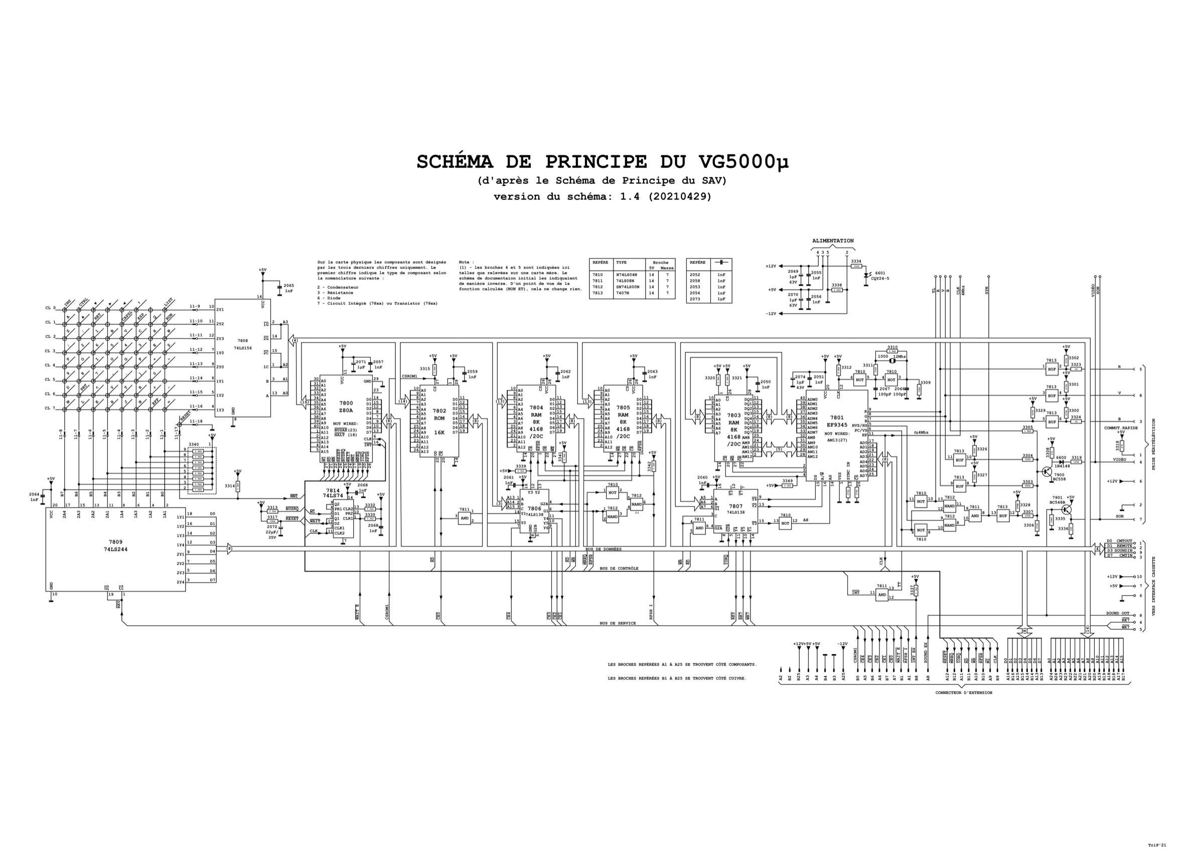
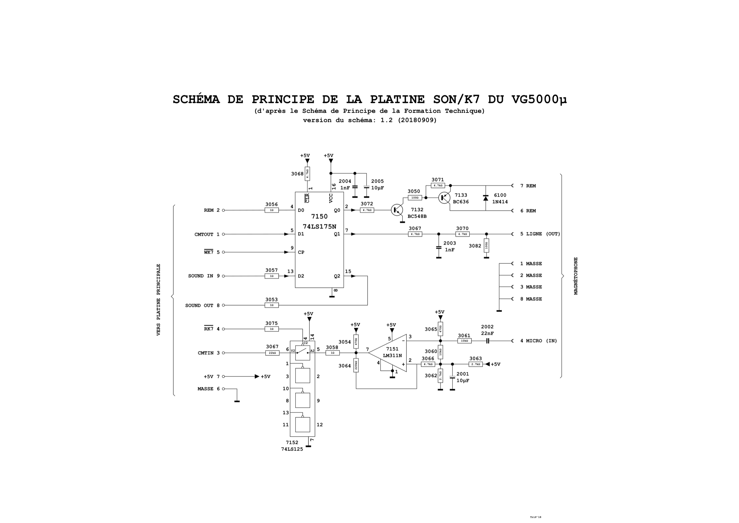
- VG-5200 — joystick interface, schematic — PDF
- VU0031 — memory expansion, schematic — PDF
- VG-5216 expansion — schematic — PDF
Provenance — these are not period Philips documents
All three PDFs carry the author "Fred" in their metadata and are dated August 2019: they are amateur surveys and redraws, not manufacturer documentation. The VG-5200 schematic is a KiCad drawing that carries its author's own warning: "address decoding is very incomplete!!".
The two images (vg5000-schema-v1-4.png, -k7-v1-2.png) are version-numbered but
their authorship remains unverifiable.
The VG-5200 is not a machine: it is a joystick interface for the VG-5000 bus, just as the VG-5216 is an expansion.
Sources & attribution
- MAME —
src/mame/philips/vg5k.cpp(BSD-3-Clause): the Z80 at 4 MHz, the EF9345 SGS-Thomson video controller, and the "not working" flag carried by thevg5kmachine — hence this page's caveat about using the emulator as a reference — https://github.com/mamedev/mame/blob/master/src/mame/philips/vg5k.cpp
Review & corrections
How this space is used
Spotted a wrong value, an outdated procedure, a chip reference that does not match your board? Say so here, with what you observed (model, board revision, serial number, measurement). Every report is cross-checked against a source before anything changes — an unverifiable correction is published as “reported by …, not cross-checked” rather than silently applied.
Reading is open to everyone; posting requires signing in with Discord. Reports from the wiki's declared reviewers are handled first; anyone else's are read too, but go through a human before anything is changed.