Game Boy Advance¶
Nintendo's 32-bit handheld (2001, AGB), GB/GBC backward-compatible. Its stock Achilles' heel: a very dark reflective screen → the IPS screen mod is almost unavoidable. Available as the SP (AGS-001 frontlit / AGS-101 backlit) and Micro.
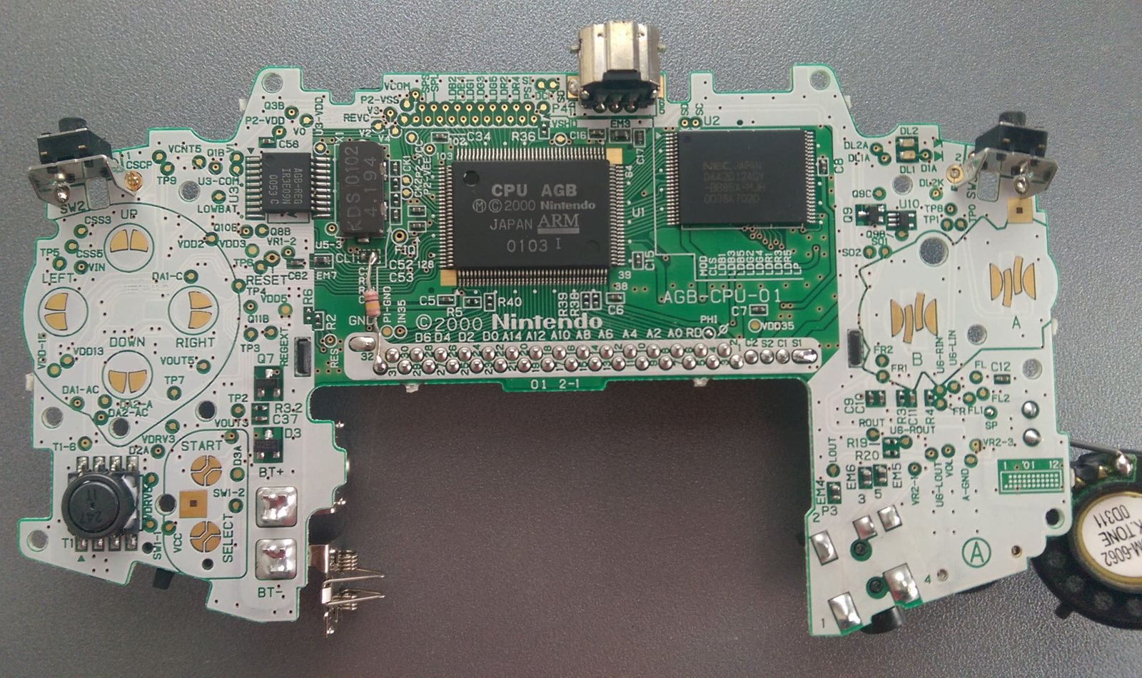
Identification¶
| Field | Value |
|---|---|
| Manufacturer | Nintendo |
| Releases | AGB 2001 · SP (AGS-001/101) 2003 · Micro 2005 |
| CPU | ARM7TDMI @ 16.78 MHz (+ a GB core for backward-compat) |
| Screen | AGB reflective (dark); SP frontlit then backlit (AGS-101) |
| Backward-compat | GB / GBC |
Architecture (detail)¶
| Block | Chip / value | Notes |
|---|---|---|
| CPU | ARM7TDMI @ 16.78 MHz | + a Sharp LR35902 (GB) core for backward-compat |
| LCD | 240×160, 15-bit (32768 colours) | AGB reflective (dark) — hence the IPS mod |
| Sound | 4 GB channels + 2 PCM channels (Direct Sound) via DMA | |
| RAM | IWRAM 32 KB (fast, on-chip) + EWRAM 256 KB + VRAM 96 KB | |
| Media | Cartridge (up to 32 MB) + SRAM / Flash / EEPROM save |
Video: tiled modes 0-2 (up to 4 layers, incl. affine rotation/scaling on BG2/3) + bitmap modes 3-5; 128 sprites (with hardware rotation/zoom). The GB core (LR35902) is only active in backward-compat (the ARM is halted).
Models & backward-compatibility¶
| Model | Year | Screen | GB/GBC compat |
|---|---|---|---|
| AGB-001 | 2001 | reflective (dark) | ✅ |
| SP AGS-001 | 2003 | frontlit (clamshell, Li battery) | ✅ |
| SP AGS-101 | 2005 | backlit (the best official screen) | ✅ |
| Micro | 2005 | backlit, tiny, swappable faceplates | ❌ (GBA only) |
Board revisions — ⚠️ 32-pin vs 40-pin screen ✅¶
Check this BEFORE ordering a screen kit
The AGB-001 comes with two incompatible LCD connectors:
- AGB-CPU-01 to -04 → 40-pin connector;
- AGB-CPU-10 (from 2002) → 32-pin connector.
Ordering the wrong IPS kit means an unusable kit. Nintendo skipped ahead from revision -04 to -10: there is no -05 through -09.
Reading it without disassembly: as on earlier Game Boy systems, the revision number is visible inside the battery compartment, through the hole for the battery cover clip. You will read "01", "02", "03" or "04" → 40-pin, and "10" → 32-pin.
Bonus: 32-pin systems consume less current and therefore have better battery life than 40-pin ones. (Source: ConsoleMods, CC-BY-SA.)
| Model | Revisions | What it changes |
|---|---|---|
| AGB-001 | AGB-CPU-01 → -04 | Minor layout changes only, with no impact on functionality or modifications. CPU-01 and -02 tend to carry the original CPU version; later boards the "A" revision CPU. 40-pin screen. |
| AGB-001 | AGB-CPU-10 (2002) | Different LCD interface from all previous revisions: 32-pin. Lower current draw → better battery life. |
| SP AGS-001 | several, incl. AGS-CPU-30 | Revisions largely identical; the last one (AGS-CPU-30) consolidates some ICs into the Mitsumi PM B3 chip. |
| SP AGS-101 | AGT-CPU-01 (only one) | ⚠️ Not interchangeable with AGS-001 boards (and vice versa) due to the screen lighting differences. |
Telling AGS-001 and AGS-101 apart without a label
- AGS-001 = frontlit screen, with a small button under the screen on the main body that turns the lighting on and off.
- AGS-101 = backlit and more vibrant; the button only dims the screen and never switches the backlight off.
- The visual tell: with the system turned off, the 101's screen has a slight grey/green tinge. That is how to identify it when the model number label cannot be seen.
- The AGS-101 was never sold in Japan.
Hardware quirks worth knowing
- AGB-001: no AC adapter input — power supplies must feed through the battery contacts. Dual power LED: green in normal operation, red when the batteries are running low. The last Game Boy to take alkaline batteries (2 × AA). No IR transceiver (unlike the GBC).
- SP: rechargeable, user-replaceable Li-ion battery; the headphone jack is consolidated into the proprietary charging connector → a special adapter is required for headphones. D-pad and face buttons use metal tact switches instead of rubber membranes.
- Micro (OXY-001): link and charging ports combined into a single proprietary connector (special cables or an adapter needed), but the 3.5 mm headphone jack returns. No GB/GBC compatibility at all — GBA games only.
"Hardware" cartridges & links¶
- Built-in sensors: Boktai (a real solar sensor), WarioWare: Twisted! (gyro + rumble), Yoshi Topsy-Turvy (tilt), Drill Dozer (rumble) — the hardware is in the cartridge.
- e-Reader: an accessory that scans "dot-code" cards (mini-games, Mario levels, e-Cards).
- Wireless Adapter: bundled with Pokémon FireRed/LeafGreen and Emerald.
- Links: link cable (multi, single-cartridge play); GBA↔GameCube (controller/2nd screen, Game Boy Player).
Common faults¶
| Symptom | Likely cause | Lead |
|---|---|---|
| Unreadable screen without strong light | Reflective LCD (AGB) | IPS screen (mod) |
| Weak / absent sound | Audio capacitors, speaker | Recap; speaker |
| Hinge / screen (SP) | Ribbon, hinge | Replace ribbon/hinge |
| Battery contact corrosion | Leaked batteries | Clean contacts |
Step-by-step disassembly procedures ✅¶
10 procedures transcribed from the iFixit guides, with difficulty and estimated time.
| Procedure | Difficulty | Time |
|---|---|---|
| Installing Nintendo Game Boy Advance Back Panel | Easy | 1 - 2 minutes |
| Installing Nintendo Game Boy Advance Battery | Very easy | < 1 minute |
| Installing Nintendo Game Boy Advance Buttons | Moderate | 10 to 15 minutes |
| Installing Nintendo Game Boy Advance Buttons and LCD Screen | Moderate | 10 - 20 minutes |
| Installing Nintendo Game Boy Advance LCD Screen | Difficult | 20 - 30 minutes |
| Installing Nintendo Game Boy Advance Logic Board | Moderate | 15 to 20 min |
| Installing Nintendo Game Boy Advance On/Off Switch | Very easy | — |
| Installing Nintendo Game Boy Advance Shoulder Button and Side Panels | Moderate | 5 - 10 minutes |
| Installing Nintendo Game Boy Advance Speakers | Very difficult | 30 to 40 minutes |
| Cleaning sticky buttons | Very easy | 5 minutes |
Installing Nintendo Game Boy Advance Back Panel
How to remove the back panel from a Game Boy Advance.
- Remove the six back panel screws using a Tri-wing Screwdriver.
- Remove bottom back panel screw with a Phillips #1 screw driver.
Installing Nintendo Game Boy Advance Battery
Changing the battery is a snap. It's all about tab-pulling.
- Take the battery cover off by releasing the locking tab and hinging the cover away.
Installing Nintendo Game Boy Advance Buttons
Use this guide to remove the buttons in your Game Boy Advance
- Remove the rubber button pads from their pockets.
- Remove the plastic buttons and the D-pad from beneath the rubber pads with tweezers or by hand.
Installing Nintendo Game Boy Advance Buttons and LCD Screen
This section describes removing the logic board whole from the case.
- Remove the three screws on the circuit board with a Phillips #1 screw driver.
Installing Nintendo Game Boy Advance LCD Screen
Use this guide to remove the LCD screen from the Game Boy Advance.
- Using the tweezers, gently pull the ribbon from the logic board.
Installing Nintendo Game Boy Advance Logic Board
Use this guide to replace the logic board.
- Using the tweezers, gently pull the ribbon from the logic board.
Installing Nintendo Game Boy Advance On/Off Switch
Use this repair guide when debris needs to be cleared from the On/Off switch or it needs to be replaced.
- Remove the gray On/Off Switch by pulling up and away from the unit. Replace with another switch if necessary.
Installing Nintendo Game Boy Advance Shoulder Button and Side Panels
Use this guide for disassembly and for resolving jammed or finicky shoulder buttons.
- Remove left and right triggers by lifting and pulling them away from the system.
- Do the same for side panels
- For finicky or jammed triggers only. Adjust and correct triggers and reassemble. Most jammed triggers are caused by buttons misplaced or jammed in its enclosure.
Installing Nintendo Game Boy Advance Speakers
Use this repair guide in order to replace the speakers.
- Using the tweezers, gently pull the ribbon from the logic board.
Cleaning sticky buttons
Use this repair guide to clean sticky buttons.
- Use a slightly damp toothbrush to scrape in between the desired sticky buttons.
- Make sure toothbrush is not to the point of dripping water when scraping.
- Use a slightly damp toothbrush to scrape in between the desired sticky buttons.
- Make sure toothbrush is not to the point of dripping water when scraping.
Source, licence and scope
iFixit guides, under Creative Commons BY-NC-SA — attribution, non-commercial, share-alike. Only the text is reproduced; the step photos stay on iFixit. ⚠️ These guides target the model named in the title: on another revision, the screws and the order of removal may differ.
Procedure — a dead console, step by step ✅¶
What this adds
Ordered for a console, not for an arcade board: what kills these is almost never the CPU. It is, in real order, the power supply, the capacitors, the drive or the cartridge slot, and only then the logic. → PCB diagnosis
1. The power supply. Two cases, depending on the machine. External brick: ⚠️ read the marking on the machine, next to the socket, and check the adapter against it — voltage and polarity. A centre-negative machine fed centre-positive loses its fuse, sometimes its regulator; do not trust a third-party label or a generic tip. Internal supply (the machine plugs straight into the wall): mains is inside the shell. Unplug, wait, and confirm the large capacitors are discharged before touching the board. Either way, measure under load: a failing supply holds its voltage until it is asked for current.
1b. Battery and its contacts. On this machine, before anything else: corroded battery contacts, or a cell that reads fine off-load and collapses under it, give exactly the symptoms of a dead machine.
2. The fuse. Many of these machines have one right behind the socket — it is the part designed to die. Test it in continuity, out of circuit. A fuse that blows again is a short, not a fuse problem.
3. Capacitors. On most machines of this age this is the default suspect rather than a last resort — leaking SMD electrolytics eat the tracks underneath before they give any other sign. ⚠️ Not all of them are like that: some carry very few and are not recapped on principle. Read what this page says about it before reaching for the iron. → Recap
4. The cartridge connector. Cartridge contacts with isopropyl alcohol, never an abrasive eraser: it takes the gold plating off and the problem comes back worse. On the machine side, inspect the slot pins — splayed, bent or oxidised — and check continuity between slot and board.
5. The screen. Lines, a dead half, a picture that fades: it is almost always the ribbon and its solder joints, not the panel. Reseat before you order anything. If this machine has a TV output — not all of them do — test that too: it tells the screen apart from what feeds it.
6. Still nothing. Now, and only now, the logic: rails on the board, reset, clock, bus. → PCB diagnosis
Popular mods — what to buy, where, how¶
Models
AGB-001 (original GBA, unlit screen → the IPS transforms it) vs AGS-101 (GBA SP with an already-backlit screen). Tooling: tri-wing (Y) + Phillips screwdrivers, fine iron. Soldering: 🟢 · 🟡 · 🟠 · 🔴.
Backlit IPS screen — THE mod (AGB-001)¶
- Replaces the dim stock screen with a bright IPS (often brightness + adjustable palettes). Kits from FunnyPlaying (IPS v2/v3), Hispeedido. Where: FunnyPlaying, Stone Age Gamer, RetroModding…
- Install 🟡: open, swap panel + flex; recent kits are "drop-in" (little/no cutting) and are driven by touch/button; use a fitted shell if the screen is larger. → Handheld IPS page.
- ⚠️ BEFORE BUYING: check whether the system has a 32-pin or 40-pin screen — the kits are not interchangeable. Readable without disassembly in the battery compartment → Board revisions.
- Some replacement panels also output video (micro-HDMI, or composite through the Link port) → Video output.
Audio / power¶
- Prosound (clean line-out) + audio recap; USB-C / rechargeable internal battery.
Library — flashcart¶
- EZ-Flash Omega (Definitive Edition) or EverDrive-GBA X5 (Krikzz) — microSD, plug-and-play 🟢, handle save types + RTC (Pokémon). Large homebrew scene; very mature emulation (mGBA).
Cartridge RTC battery: the trap that breaks saves ✅¶
A handful of games carry a battery that keeps a real-time clock (RTC) running inside the cartridge. The problem is not the battery itself:
Replacing the battery is not enough — and it breaks existing saves
When the battery dies, the RTC resets to 01/01/2000 00:00:00. And when you replace
it, the game will not let you set the current time: the RTC stays wrong, which
breaks existing game saves. You can start a new game… or set the clock with a
homebrew tool and rescue your old saves. (Source: ConsoleMods, CC-BY-SA.)
Games affected: Pokémon Ruby, Pokémon Sapphire, Pokémon Emerald, Boktai: The Sun Is in Your Hand, Boktai 2: Solar Boy Django, Boktai 3: Sabata's Counterattack.
- Get
rtcread.zipand extract the.gbaROM from it. - Copy the ROM to your flash cart, plug it into the GBA and run it.
- With the system still running, remove the flash cart and insert the game cart.
- Start = read the clock data.
- Select = edit the clock with the D-pad. ⚠️ Do not set an invalid date.
- Start = save.
- Get
rtcread-ds.zipand extract the.ndsROM from it. - Copy the ROM to your flash card, insert both the flash card AND the game cart into the DS, then run RTC Read from the flash card.
- Start = read the clock data.
- Select = edit the clock with the D-pad. ⚠️ No invalid dates.
- Start = save.
The detail that matters
On GBA, the flash cart → game cart swap happens with the system powered on (the program is already in RAM). On DS there is no need: both slots are used at once. Modern flash carts (EZ-Flash Omega, EverDrive-GBA) otherwise emulate the RTC for their own saves.
Video output to a TV / monitor ✅¶
The GBA displays 240×160 at a non-standard frequency (~59 Hz). To show it on a TV or a monitor it must be converted to a standard resolution and matching refresh rate — which often results in frame stutter and windowed gameplay. The best solutions have no stutter and no tearing, but won't always fill the screen top-to-bottom.
Replacement panels with video out¶
| Panel | Output type | Screen type | Size |
|---|---|---|---|
| "One Chip" DSi TFT HDMI | micro-HDMI | TFT | same as stock |
| "OneChip" IPS TV Version | composite through the Link port | IPS | same |
| "OneChip" 9380 IPS | composite through the Link port | IPS | larger |
| HDMI Out Board | micro-HDMI | variable | variable |
The HDMI Out Board is not a panel: it is an HDMI board installed alongside whatever screen is already fitted. For the GBA SP there is only one panel with video out: the "OneChip" 9380 IPS (larger than the stock screen, composite output).
Consolizers (GBA motherboard + FPGA HDMI)¶
FPGA boards with HDMI out that connect to a GBA motherboard: real hardware on a TV, played with a controller. All are DIY kits — you must supply the motherboard.
| Consolizer | Soldering required | Controller | Pre-assembled available |
|---|---|---|---|
| GameBox GBHD Advance | yes | SNES | ✅ |
| gbaHD (open source) | yes | SNES | ❌ |
| IntecGaming GBA HDMI | no | SNES, Bluetooth | ❌ |
| Game-Tech GBA (FaceHugger / full case variants) | yes | SNES | ✅ |
Without touching the console¶
- Game Boy Player (GameCube): plays GB / GBC / GBA cartridges through the GameCube's TV output. The official disc only outputs 480i/480p → the homebrew Game Boy Interface (GBI) is much better, and Swiss can force 240p. → see GameCube and the Swiss / GC Loader page.
- With no console mods at all: keep the official boot disc and downscale 480p to 240p with an Extron Emotia or similar. Example chain: GC/GBP component cables → component-to-VGA converter → Extron Emotia → RGB monitor. The result looks very good (240p scanlines), but it is complicated and expensive — not recommended unless you already own the equipment.
- MiSTer FPGA: can't read original carts, but it is a lag-free option with RGB, VGA and HDMI up to 1440p. The most output flexibility — at the cost of original hardware and accessories.
- Wii U Virtual Console: software emulation (so some lag) but excellent.
- On CRT: set to 480p widescreen, GBA games run "pixel perfect" and fill the screen — the GBA's 160 vertical lines multiply exactly by 4 to make 640.
- On 1080p: as GBA games are 3:2, two aspect-correct modes — 1620×1080 by default (fills top to bottom, pillar boxes, ×6.75) or 1440×960 as an integer ×6 scale (black bars on all sides, but a sharper picture).
- Screen smoothing is available in the options menu or via the right thumbstick.
Region¶
None: the whole Game Boy line, including GBA / SP / Micro, is region free — see Game Boy § Region.
Capacitor list (per reference) ✅¶
Source: Console5 TechWiki. Game Boy Advance (AGB-001) — 4 caps (references in CP):
| Ref | µF | V |
|---|---|---|
| CP1 | 100 | 4 |
| CP2 | 100 | 6 |
| CP3 | 470 | 6 |
| CP4 | 100 | 4 |
Photos / assets¶
(To add: AGB board, screen, audio area.)
Advanced repair
Screen (AGS-101 / IPS mods, backlight), cartridge contacts, speaker. Methods: PCB fault-finding · Traces & vias · Recap.
Sources & attribution¶
- Wikipedia — Game Boy Advance — CC-BY-SA — https://en.wikipedia.org/wiki/Game_Boy_Advance
- Console5 TechWiki — Game Boy Advance (recap BOM per reference) — https://wiki.console5.com/wiki/Game_Boy_Advance
- ConsoleMods Wiki — Game Boy Advance Model Differences — CC-BY-SA — AGB-CPU-01→04 (40-pin) vs AGB-CPU-10 (32-pin), reading the revision through the battery cover clip hole, AGS-001 vs AGS-101 (grey/green tell), AGT-CPU-01 not interchangeable, Micro specifics — https://consolemods.org/wiki/GBA:Model_Differences
- ConsoleMods Wiki — Real Time Clock (RTC) Fix — CC-BY-SA — games affected, rtcread procedures on GBA and DS — https://consolemods.org/wiki/GBA:Real_Time_Clock_(RTC)_Fix
- ConsoleMods Wiki — Video Output Notes — CC-BY-SA — panels with video out, consolizers, Game Boy Player/GBI/Swiss, Extron Emotia, MiSTer, Wii U scaling modes — https://consolemods.org/wiki/GBA:Video_Output_Notes
- ConsoleMods Wiki — Region Information — CC-BY-SA — the Game Boy line (GBA included) is region free — https://consolemods.org/wiki/Game_Boy:Region_Information
What we did not transcribe (and why)
On the GBA side, the ConsoleMods pages Funny Playing IPS LCD, TV-Out IPS Kit, Screen Replacement, Power Fuse Replacement, USB C Port and Voltage Regulator Board Upgrade are empty to this day (red links). There is therefore no written procedure to bring home for those mods: they are named here (products and principle), with no invented steps.
Image:
-
gba-board.jpg— gekkio (Joonas Javanainen), CC BY 4.0 — https://commons.wikimedia.org/wiki/File:Game_Boy_Advance_motherboard_front.jpg

Review & corrections
How this space is used
Spotted a wrong value, an outdated procedure, a chip reference that does not match your board? Say so here, with what you observed (model, board revision, serial number, measurement). Every report is cross-checked against a source before anything changes — an unverifiable correction is published as “reported by …, not cross-checked” rather than silently applied.
Reading is open to everyone; posting requires signing in with Discord. Reports from the wiki's declared reviewers are handled first; anyone else's are read too, but go through a human before anything is changed.