Sega Mega-CD / Sega CD¶
The CD-ROM add-on for the Mega Drive (1991). Mega-CD in JP/EU, Sega CD in the US. Adds a second 68000, a CD drive, more RAM and a zoom/rotation ASIC. Two models; typical faults: optical drive, gear (Model 1) and capacitors.
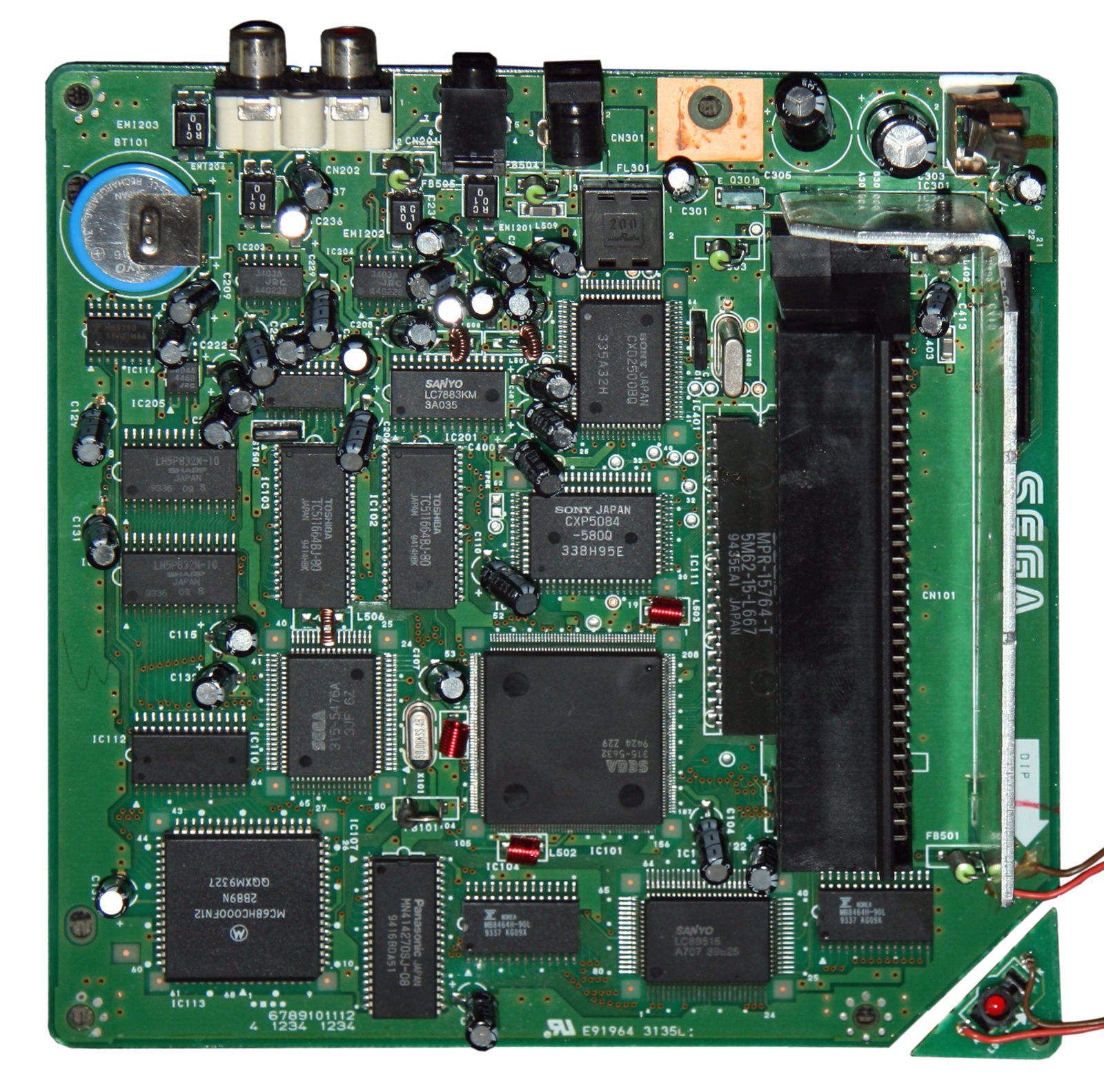
Identification¶
| Field | Value |
|---|---|
| Manufacturer | Sega |
| Release | 1991 (JP), 1992 (export) |
| Type | CD-ROM add-on for Mega Drive / Genesis |
| Models | Model 1 (under the MD, front-loading) · Model 2 (beside, top-load) |
| Region | Aligned with the Mega Drive |
Architecture (additions)¶
| Block | Chip | Clock | Role |
|---|---|---|---|
| CPU | 2nd Motorola 68000 | 12.5 MHz | faster than the MD's 68000 (7.67 MHz) |
| Graphics | dedicated ASIC | rotation / scaling ("Mode 7-like" effects) | |
| Sound | RF5C164 PCM | 8 PCM voices (on top of the MD's YM2612/PSG) | |
| Memory | 768 KB program RAM + 256 KB PCM RAM + CD buffer | ||
| Save | 8 KB internal backup RAM (battery) | + optional RAM cartridge |
The Mega-CD is a second computer driven via the Mega Drive's expansion bus: the MD's 68000 and the Mega-CD's cooperate.
Models & region¶
- Model 1 (1991): a motorised tray under a Mega Drive Model 1 (front tray). A loading motor can fail (a common repair).
- Model 2 (1993): top-loading, more reliable, under an MD2.
- Plus the CDX / Multi-Mega and Wondermega / X'Eye combos (see below).
- Region lock: the Mega-CD is region-locked (BIOS) → an import game needs a region-free BIOS, a switch, or a mod/ODE.
Either model works with either console
Only two models were ever produced, radically different in design but with the same functionality. Both take the same tip-negative 9 V AC adapter as the Model 1 Mega Drive, and either model will work with either a Model 1 or Model 2 console:
- Mega-CD 1 under a Model 2: simply remove the console's rubber feet — this is even mentioned in the Model 2 manual.
- Mega-CD 2 with a Model 1: the console partially hangs off the side; Sega included an extension piece to provide full support.
Model 1 (front-loading, 1991-1993) ✅¶
Easily distinguished by its front-loading tray and the fact that it sits directly underneath the Mega Drive, with the expansion connector protruding on the right-hand side.
- No controls on the add-on itself: the tray is opened using the system menu or by resetting the attached console, and closed using the system menu.
- Green "Ready" and red "Access" LEDs on the front bezel. Japanese and PAL Model 1s also have small diagrams on the front showing what the different LED light patterns mean.
- All connections grouped at the rear: DC input, RCA audio out, 3.5 mm audio in.
- Drive mechanisms: all Japanese and most North American units have a Sony drive; most PAL units a JVC drive.
Socketed BIOS = easy region mod (spot it before buying)
Very early Model 1 Mega CDs use an EPROM BIOS chip placed inside a socket, which makes swapping it for a region-free BIOS (or another region/version) much easier — no desoldering. These often have a serial number starting with A10.
Model 1 reliability: the known weak points
The Model 1 is plagued with reliability issues:
- overstretched tray belts;
- dirty limiter switches;
- faulty helix / Archimedes screws on Sony drives;
- leaky capacitors.
⚠️ The main board in particular contains a number of SMD capacitors which must be replaced — even if there are no visible signs of leakage. Leaky capacitors can also be found on the "sub" board in the vicinity of the voltage regulator. Systems with a JVC drive can additionally suffer from bad capacitors on the drive controller board. (Source: ConsoleMods, CC-BY-SA.)
Model 2 (top-loading, 1993-1995) ✅¶
A drastic redesign: the front-loading tray gives way to an inexpensive top-loading design. The Mega Drive sits on a thin base housing the motherboard, with the drive mechanism to the side. A lone disc access LED on the top front (the green "Ready" LED was omitted); rear connections exactly the same as the Model 1. This is the most common version, especially outside Japan, and the only one released in Brazil.
Far more robust — with one exception
The Model 2 is far more robust: no leaky capacitor issues, and no tray issues given its top-loading nature.
Its most common fault, by far, is the FUSE. It blows:
- if the wrong AC adapter is used;
- or if the Mega Drive is attached or removed while the CD is still plugged into power.
The good news: this is easily repairable and restores the add-on to working order. ⚠️ So: always unplug the Mega-CD's power before handling the console.
Model 2 board revisions¶
Six board revisions exist: five designed and manufactured by Funai, one by Sega. All except the Sega board incorporate all of the CD processing, the drive controller circuitry and the drive activity LED onto the motherboard.
Spotting a Sega board without opening up
For all regions, systems with a Sega board have an "A" at the end of the model number — e.g. MK-4102A (North America) or HAA-2912A (Japan).
| Revision | Maker | What characterises it |
|---|---|---|
| BE2200G02A01 | Funai | The earliest, found only in Japanese Mega CD 2 units. Easily discerned by a small "bodge" PCB glued directly on top of the 315-5476A PCM chip and its RAM. The only Model 2 variant to use the 315-5548 (MCE2) ASIC, normally found in non-Japanese Model 1s. |
| BE2200G02A02 | Funai | The first North American variant, mainly in early Model 2s. Moves to the 315-5632 (MCE3) ASIC but still features the "bodge" PCB. |
| BE2200G02B02 | Funai | Like the 2A02 but with minor layout changes. The first revision for PAL Model 2s. |
| BE2200G02C02 | Funai | Like the previous one, but incorporates the contents of the "bodge" into the board. Introduced from serial numbers T30282001 and later. |
| 171-6528C | Sega | The only revision designed by Sega, considerably smaller: the drive controller circuitry is offloaded onto a separate PCB mounted underneath the laser mechanism, and the activity LED onto another board screwed to the bottom case. |
| BE2200G02C22 | Funai | The final revision, heavily consolidated: the audio DACs and op-amps are combined into a single chip, the 315-5619. Despite this, audio quality is not discernibly different from the original design. Drive circuitry and LED integrated, like other Funai boards. |
BIOS and Sega boards: asymmetric compatibility
BIOS ROMs meant for the Sega 171-6528C revision are "universal" and will work in any Model 2. However, the BIOS included with earlier Funai boards is NOT compatible with Sega boards.
Naming trap: the "Sony" board is not made by Sony
The service manual refers to the 171-6528C revision as the "Sony" model, even though it was designed by Sega — and units carrying it can be found with either a JVC or a Sony laser. Do not confuse the board maker (Sega or Funai) with the drive maker.
Model 2 lasers¶
| Board type | Possible lasers |
|---|---|
| Funai boards | Sony KSS-210A or Samsung SOH-O4T |
| Sega board (171-6528C) | JVC Optima-6 or Sony KSS-240A |
Identifying the laser at a glance (Sega boards)
On Sega-board mechanisms, the spindle gives it away: silver spindle = Sony laser, black spindle = JVC laser.
Library & FMV¶
The cradle of FMV (full-motion video): Sewer Shark, Night Trap (central to the US violence debates → creation of the ESRB), but also genuinely good games (Sonic CD, Lunar, Snatcher, Final Fight CD). The limited video quality (few colours) is typical of the era.
Common faults¶
| Symptom | Likely cause | Lead |
|---|---|---|
| Won't read CDs / erratic reads | Worn / misaligned laser | Adjust the laser pot, or replace the optical block |
| Tray/loading fails (Model 1) | Broken plastic gear | Replace the Model 1 gear (a known part) |
| Tray won't fully open/close, laser no longer lifts (Model 1) | Overstretched belt (the Model 1's number-one fault) | Replace the belt — square 24 × 1.2 mm |
| Erratic tray (Model 1) | Dirty limiter switches; faulty helix screw on Sony drives | Clean the switches; drive mechanism |
| Degraded sound/video, corrosion | Leaking capacitors (incl. SMD) | Recap — ⚠️ on the Model 1, do it even with no visible leakage; remember the sub board near the regulator and, on JVC drives, the drive controller board |
| Model 2 completely dead | Blown FUSE — wrong adapter, or console attached/removed while powered | Replace the fuse (an easy repair) → Model 2 |
| Lost saves | Flat internal RAM battery (or supercapacitor on the X'Eye) | Replace the battery, or switch to FRAM (no battery at all) |
| Import game refused, or CD unit won't work with the console | Double region lock (game and host console) | Region-free BIOS |
| No communication with the MD | Connector/contacts | Clean the expansion bus |
Original service manual ✅¶
Manufacturer manual archived locally. It typically carries the schematics, the block diagram, the expected voltages and waveforms, the parts list and the disassembly procedures — the reference when a symptom matches no known fault.
Status
A manufacturer document with no explicit licence, kept for preservation (machine long out of production). Source: Internet Archive.
Step-by-step disassembly procedures ✅¶
5 procedures transcribed from the iFixit guides, with difficulty and estimated time.
| Procedure | Difficulty | Time |
|---|---|---|
| Complete Disassembly of Sega CD | Moderate | 20 to 40 minutes |
| Sega CD Motherboard/AC Power Board Removal | Moderate | 20 to 40 minutes |
| Disassembling Sega CD Plastic Housing | Easy | 5 to 10 minutes |
| Installing Sega CD CD Tray | Moderate | 15 to 30 minutes |
| Installing Sega CD Genesis Connector | Moderate | 20 to 40 minutes |
Complete Disassembly of Sega CD
- Teardown complete!
Sega CD Motherboard/AC Power Board Removal
Before attempting this guide complete the CD Tray Removal Guide
- Remove 2 screws from small metal casing using a medium phillips screwdriver
- 1/2 inch bronze screws (2)
- Carefully lift metal case up to expose motherboard.
- Caution: There is a wire strip running through metal plate that is soldered to motherboard and power supply board, thus plate cannot be completely removed. Do NOT force plate upwards.
- Carefully lift off metal plate, motherboard, and CD tray circuit board and flip over as shown
- Caution: There is a wire strip running through metal plate that is soldered to motherboard and power supply board, thus motherboard cannot be completely removed. Do NOT force upwards.
- With motherboard and CD try circuit board set aside, remove 2 screws from power supply using a medium phillips screwdriver
- 1/2 inch bronze screws (2)
- Remove power supply from console by lifting up
Disassembling Sega CD Plastic Housing
- Remove the six screws on the underside of the console using a medium phillips screwdriver
- 1/2 inch bronze screws (6)
- Remove the 2 screws on the side of the console that attach the Genesis adapter to the rest of the unit using a medium phillips screwdriver.
- 3/8 inch black screws (2)
- Ensure the lock on the left of the case is in the unlock position (slide left as shown) before removing the case.
- Remove case by lifting up left side, then using the prying tool, pry the cover out of the genesis attachment and lift upward.
Installing Sega CD CD Tray
- Remove large metal plate by unscrewing the three screws using a medium phillips screwdriver.
- 1/2 inch bronze screws (3)
- Carefully lift the metal plate to remove
- Remove the two screws from the plastic bar.
- 3/8 inch bronze screws (2)
- Remove the 4 screws to remove CD tray using a medium phillips screwdriver
- 3/8 inch black screws (4)
- Carefully unplug wire connection to optical reader
Installing Sega CD Genesis Connector
- Remove 2 screws that attach the Genesis adapter to the console using a medium phillips screwdriver
- Unplug Genesis adapter by carefully pulling it out
- Remove the four screws from the metal plate as shown using a medium phillips screwdriver
- 1/2 inch bronze screws (4)
- Carefully remove metal cover from connector as shown by sliding it up and out
Source, licence and scope
iFixit guides, under Creative Commons BY-NC-SA — attribution, non-commercial, share-alike. Only the text is reproduced; the step photos stay on iFixit. ⚠️ These guides target the model named in the title: on another revision, the screws and the order of removal may differ.
Procedure — a dead console, step by step ✅¶
This machine does not run on its own
It needs a Mega Drive. Before opening anything, prove the host is good with a plain cartridge — otherwise you spend the day inside the add-on for a fault that is not in it. → Mega Drive
What this adds
Ordered for a console, not for an arcade board: what kills these is almost never the CPU. It is, in real order, the power supply, the capacitors, the drive or the cartridge slot, and only then the logic. → PCB diagnosis
1. The power supply. Two cases, depending on the machine. External brick: ⚠️ read the marking on the machine, next to the socket, and check the adapter against it — voltage and polarity. A centre-negative machine fed centre-positive loses its fuse, sometimes its regulator; do not trust a third-party label or a generic tip. Internal supply (the machine plugs straight into the wall): mains is inside the shell. Unplug, wait, and confirm the large capacitors are discharged before touching the board. Either way, measure under load: a failing supply holds its voltage until it is asked for current.
2. The fuse. Many of these machines have one right behind the socket — it is the part designed to die. Test it in continuity, out of circuit. A fuse that blows again is a short, not a fuse problem.
3. Capacitors. On most machines of this age this is the default suspect rather than a last resort — leaking SMD electrolytics eat the tracks underneath before they give any other sign. ⚠️ Not all of them are like that: some carry very few and are not recapped on principle. Read what this page says about it before reaching for the iron. → Recap
4. The drive. On this machine it is the dominant failure point. In order: does the tray move, does the disc spin, is the lens clean (cotton bud, isopropyl alcohol, no pressure), do the rails slide freely. A laser that no longer reads gets replaced; the gain pot is not something to tweak blind — that is the move that finishes off a laser that was still good.
5. Video output. Isolate the machine from the display: another cable, another TV, another input. A sizeable share of "dead consoles" are a dead cable, or a display that will not lock onto what this machine outputs — see the video section of this page for what that is.
6. Still nothing. Now, and only now, the logic: rails on the board, reset, clock, bus. → PCB diagnosis
Recap¶
The Mega-CD/Sega CD has leaking SMD capacitors — the #1 cause of "no boot / no audio" faults. Recap recommended. Beware the PCB variants: Model 1, and Model 2 in Funai (P/N BE2200…) or Sega (P/N 171-6528C, called the "Sony" model by the service manual — see the naming trap above) versions — the cap list differs. Source (cap-maps per variant): Console5 TechWiki (v1 · v2). (Per-CXX BOM: cap-maps are images on the source side — to transcribe once a text list is available.)
Replacing the tray belt (Model 1) ✅¶
One of the most common faults with the Model 1: the belt that moves the tray becomes overstretched with age. Symptoms: the tray not fully closing or opening, and above all the laser mechanism failing to lift up to read a disc. A fairly simple fix requiring only simple tools and some patience.
The exact part
A 24 mm × 1.2 mm square belt. Console5 sells an exact replacement — that is the one to order.
Tools and materials: JIS/Phillips screwdrivers, a spudger, the belt above, white lithium grease (optional), isopropyl alcohol (optional).
(Procedure for Sony drives.)
- Flip the Sega CD over and remove the six screws on the bottom, then flip it right side up and unscrew the two black screws near the expansion connector. Lift the top cover off, minding the expansion connector as you go.
- Undo the three screws on the RF shield over the CD drive (one on each side, another at the back which also screws into the sub board). Lift the shield away.
- Undo the four black screws holding the CD drive to the bottom case. Carefully lift the drive and disconnect the ribbon cable to the motherboard.
- With the drive removed, unscrew the two screws securing the top clamp assembly and lift it out.
- Inside the opening near the spindle is a set of teeth belonging to a large black gear, part of the tray-opening mechanism. Using a spudger, rotate the gear clockwise to disengage the laser and open the tray. ⚠️ Move it slowly: forcing it damages the teeth.
- With the tray fully open it can be pulled out. First remove a small cover near a tab at the rear of the tray: twist a flathead or spudger underneath it to pop it off.
- Locate the two tabs near the front of the drive chassis that hold the tray in place. Insert a small screwdriver or toothpick into the hole on each tab and pull the tab away from the tray while carefully pulling the tray out. After both side tabs are pulled back, pull back on the rear tab (next to the cover you just removed) while continuing to slowly pull the tray out. Patience is key — do not rush or force it.
- One piece remains: the cover over the white pulley the belt wraps around. Release the tab near the spindle, then slide the cover to the left: it drops away, revealing the belt in full.
- Remove the old belt and carefully fit the new one.
Re-grease — and above all: NO spray grease
This is a good time to relubricate both the tray mechanism and the tray itself, as the original grease hardens with age. Remove the old grease with a cotton swab dipped in isopropyl alcohol until it is all gone, then apply new grease to those same points.
- Do not apply grease to areas which did not originally have it, including the gear teeth.
- Pure lithium grease is highly recommended; white lithium grease also works well.
- ⚠️ Never use spray-on lithium grease: it contains additives that can degrade plastic.
- Reassemble the drive: carefully manipulate the large black gear to help pull the tray back in and lift the laser up. Place the clamp back on and screw it in.
- Reconnect the ribbon cable and place the drive inside the Sega CD — without screwing everything back in just yet.
- Put the top case back on, attach a console and connect the setup as normal.
- Test: the tray must fully extend and retract without difficulty or excessive noise. Insert a disc and make sure it loads and that the laser lifts up to read it. Only then fully reassemble.
Region-free BIOS mod ✅¶
The double lock
All Sega/Mega CD games are region locked. In addition, the vast majority of CD units will only function on consoles that match their region (a PAL Mega CD will only work with a PAL Mega Drive). A hacked region-free BIOS fixes both issues at once: it ignores the region flag in the game and the region setting of the attached console.
Advanced mod — the real risk
If care is not taken while removing the original BIOS chip, multiple solder pads and traces can be lifted, which will result in an extremely difficult repair. The key to avoiding this is patience.
Machines covered: both Mega-CD models, but also the CDX/Multi-Mega, both Wondermega models and the X'Eye — the latter requiring a different installation, as their BIOS chips are SMD SOP-40 packages with no modern equivalents (→ MultiBIOS replacement PCB from Will's Console Modifications, or an open-source adapter). The Aiwa Mega CD uses exactly the same through-hole BIOS chip as the Model 2.
Materials: leaded solder, flux, a 27C1024 EPROM (standalone CD units), a 40-pin DIP socket (preferably dual wipe), isopropyl alcohol 91 % or higher / flux remover. Tools: JIS/Phillips screwdriver, chip puller (if the BIOS is already socketed), a temperature-controlled iron, a desoldering gun (highly recommended), a hot air rework station (SMD BIOS), a multimeter, an EPROM programmer, and hex editor software or any program that can perform byteswapping.
BIOS removal and socket installation¶
- Flip the Sega CD over and remove the six screws on the bottom — plus, on the Model 1, the two black screws near the expansion connector. Lift the top cover, minding the connector. (Aiwa Mega CD: flip over the "Game Unit" section and remove the ten screws.)
- North American and PAL units: remove the RF shielding covering the motherboard.
- Remove the motherboard from the case.
- Locate the BIOS — a standard 40-pin DIP chip:
- Model 1 and Model 2: close by the expansion connector. ⚠️ On the Model 2 it sits directly underneath the expansion connector, giving far less room to work with — be very mindful of this.
- Aiwa Mega CD: on the right-hand edge of the motherboard, right next to the main 68000 CPU.
- Model 1 shortcut: if the BIOS is a socketed EPROM, ignore the desoldering steps — remove it with a chip puller (or, very carefully, a flathead) and go straight to programming.
- Otherwise: flip the motherboard over, apply fresh solder and/or flux to the 40 solder joints, then desolder with the desoldering gun, being careful not to heat one area for too long. Each pin should move freely; if a pin still isn't moving, resolder it, apply more flux and desolder again until it is free.
- Once desoldered, the chip should simply fall out when the board is flipped over. Inspect that no pads or traces have been damaged, then clean the area thoroughly (swabs + IPA or flux remover).
- Place the 40-pin DIP socket where the BIOS chip was, orientation matching the silkscreen. Holding it against the board, solder two opposite corners to anchor it, ensuring the socket sits flush.
- Finish soldering the socket, applying neither too little nor too much solder per joint.
- Place the original BIOS chip into the socket, fully inserted, without bending any pins; make sure its pins are clean and free of excess solder.
- Reassemble far enough to test with a Mega Drive. If the unit still works normally, proceed to programming the region-free BIOS.
Programming and installing the region-free BIOS¶
- Download the region-free BIOS matching your model. Any region BIOS can be chosen, but ⚠️ the model must match — you cannot use a Model 2 BIOS on a Model 1.
- ⚠️ The BIOS must be byteswapped if it hasn't been already. Some EPROM programming software can do this; otherwise use Hex Workshop, AFS ROM Suite MD or similar. (This is the classic omission that produces a dead-on-arrival mod.)
- Insert a 27C1024 EPROM into the programmer and configure the software for your particular EPROM. If unsure about voltage settings, look up the exact part number and its datasheet, which gives the proper read and program voltages.
- Run the blank check: the EPROM must be completely blank or it cannot be written to. If it isn't, erase it under strong UV light (inexpensive EPROM erasers are widely available).
- Load the BIOS file — no other changes are needed beyond making sure it is byteswapped.
- Program, then verify. If programming failed: double-check the programmer is properly configured for your EPROM and that no other settings were changed, erase and try again.
- Insert the programmed EPROM into the socket, all pins lined up, and test.
Alternative without heavy desoldering
A multibios mod is available for the Model 1 Sega/Mega CD (ConsolesUnleashed website), and for combo units the MultiBIOS PCB mentioned above — handy when you want several switchable regions rather than a single fixed BIOS.
Permanent saves — the FRAM mod (no more battery) ✅¶
The Sega CD holds saved games in a static RAM (SRAM) chip on its motherboard. That SRAM requires constant power to retain saves, supplied by an on-board coin cell battery — or, on some systems such as the JVC X'Eye, by a supercapacitor. If the battery dies or the supercapacitor loses charge, all game saves are lost.
The permanent fix: replace the SRAM with a ferroelectric RAM (FRAM) chip, which retains information regardless of whether power is available. Optionally, a larger capacity FRAM can be combined with physical switches to give four separate data banks; and a replacement BIOS lets the BIOS see the entire capacity of the chip, allowing quadruple the memory blocks.
Applies to the whole family
All Sega CD variants, including the LaserActive Sega PAC, all combination consoles (X'Eye, both Wondermegas, CDX) and even the Aiwa Mega CD.
Choosing the chip¶
| Part | Capacity | When to choose it |
|---|---|---|
| FM16W08-SG | 64 KB | Matches the stock SRAM size — go with this unless you plan on bankswitching or a replacement BIOS |
| FM18W08-SG | 256 KB | The extra space is not seen by the stock BIOS, but can be bankswitched or used with a replacement BIOS that accesses it |
The suffix matters
Some chips are sold without the trailing -SG. -SG = SOIC package (the one you
want); -PG = through-hole, NOT suitable for this mod.
Identifying the stock SRAM per machine¶
| Chip marking | Machine |
|---|---|
| MB8464A-10L | Model 1, or Funai-produced Model 2 |
| MB8464A-80L or XL J6265AF-10SL | Sega-produced Model 2 |
| MB8464H-10LL | Aiwa Mega CD |
| LC3664BML-10 | Sega CDX — ⚠️ there are two of them: replace IC10 |
| MS6264CLL-10FC | PAC-S1 / PAC-S10 (LaserActive) |
| LC3564QM | Wondermega, Wondermega M2, JVC X'Eye |
Materials: the chosen FRAM, two SPDT switches (or one DPDT), insulated or magnet wire, leaded solder, low melt solder (if no hot air station), flux, desoldering braid, IPA at least 90 %, cleaning swabs (microfibre/foam rather than cotton, which leaves strands behind). Tools: soldering iron, hot air rework station (optional), multimeter with continuity mode, tweezers, Phillips screwdriver.
Removing the SRAM¶
- Disassemble the console and pull out the motherboard.
- Locate the SRAM (table above) and cover nearby components with Kapton tape or foil to protect them from heat.
- Hot air at 360 °C, medium air flow. Preheat from 4-5 inches away, distributing the heat very evenly around the chip for ~30 seconds. Then circle the perimeter of the chip with the nozzle, never applying heat to one location for too long.
- Have patience — this takes time, especially if there is adhesive underneath. At this temperature, and evenly applied, the hot air should not hurt the board.
- Keep checking with tweezers by grabbing the side of the chip and gently trying to lift it without applying force. When ready, it comes off easily. ⚠️ If force is applied here, pads and traces may pull up along with the chip.
- Once separated, turn off the hot air, then wick up any remaining solder on the pads with braid (flux helps) to leave an even surface.
Special cases
- No hot air station: use low temperature solder (ChipQuik). ⚠️ Especially recommended for the Aiwa Mega CD, whose motherboard is very sensitive to heat. Clean the ChipQuik away thoroughly with braid afterwards: it would contaminate the FRAM's solder joints.
- X'Eye: the SRAM is epoxied to the bottom of the motherboard and must be removed with hot air. Alternatively, a flex adapter can be soldered in without removing the SRAM at all.
Installing the FRAM¶
If using an FM18W08 and planning on bankswitching or an alternative BIOS, lift both pins 1 and 26 before fitting: these are the address pins that will be attached to the switches (two SPDT or one DPDT).
Combo units (CDX/Multi-Mega, Wondermega/X'Eye) — recap¶
Several all-in-one machines integrate a Mega Drive + Mega-CD in a single case: the Sega CDX (US) / Multi-Mega (EU), and the Wondermega (Sega/JVC, JP), released in the US as the JVC X'Eye. They are recapped like a Mega-CD and a Mega Drive combined (multiple boards). Lists from Console5 TechWiki.
Sega CDX / Multi-Mega ✅¶
Three boards. Notable chips: 68000 MC68H000FN8 (Genesis), Z80 84C00, VDP/IO/YM2612 315-5660, 68HC000FN12 (Sega CD), 315-5632 GPU, 315-5476A PCM, MB3790 backup. Laser: Sanyo SF-C93 (10-pin version!).
CDX — CPU board (1EA4B13A00400) — 6 caps
| Ref | µF | V |
|---|---|---|
| C27, C90 | 100 | 6.3 |
| C29, C46, C107, C108 | 220 | 6.3 |
CDX — Power board (1EA4B11A09301) — 6 caps
| Ref | µF | V |
|---|---|---|
| C201 | 470 | 16 |
| C204 | 4.7 | 50 |
| C206, C207, C209 | 470 | 10 |
| C211 | 100 | 6.3 |
CDX — CD player board (1EA4B11A09202) — 27 caps
| Ref | µF | V | Ref | µF | V |
|---|---|---|---|---|---|
| C502 | 47 | 6.3 | C635 | 100 | 16 |
| C504 | 47 | 6.3 | C667 | 22 | 16 |
| C513 | 47 | 6.3 | C668 | 47 | 6.3 |
| C522 | 10 | 16 | C673 | 100 | 6.3 |
| C523 | 100 | 6.3 | C674 | 47 | 6.3 |
| C533 | 10 | 16 | C677 | 220 | 6.3 |
| C534 | 100 | 6.3 | C678 | 220 | 6.3 |
| C555 | 100 | 6.3 | C680 | 22 | 16 |
| C561 | 33 | 10 | C714 | 470 | 16 |
| C575 | 100 | 6.3 | C735 | 22 | 6.3 (polymer, not in kit) |
| C601 | 47 | 6.3 | C737 | 220 | 6.3 |
| C604 | 10 | 16 | C775 | 22 | 16 |
| C605 | 47 | 6.3 | |||
| C607 | 47 | 6.3 | |||
| C634 | 47 | 6.3 (polymer, not in kit) |
Wondermega / X'Eye ✅¶
Two very different models. RG-M1 (Wondermega 1, the "hi-fi" one) = 5 boards; RG-M2 (Wondermega 2 / X'Eye) = 2 boards. Note: high capacitor count.
Wondermega RG-M1 — Sound/Control (ENB-159B) — 26 caps
| Ref | µF | V | Ref | µF | V |
|---|---|---|---|---|---|
| C707, C708 | 10 | 16 | C767, C768 | 47 | 6.3 |
| C711 | 1 | 50 | C781, C782 | 10 | 16 |
| C712, C716, C718, C719 | 4.7 | 25 | C829, C830 | 10 | 16 |
| C720 | 47 | 6.3 | C833, C834 | 10 | 16 |
| C721 | 22 | 6.3 | C857, C858 | 10 | 16 |
| C743, C744, C753 | 10 | 16 | C881, C882 | 10 | 16 |
| C761 | 4.7 | 25 | |||
| C763 | 47 | 6.3 |
Wondermega RG-M1 — Video (ENB-159-6) — 11 caps
| Ref | µF | V |
|---|---|---|
| C674 | 220 | 16 |
| C676 | 220 | 6.3 |
| C841 | 4.7 | 25 |
| C842, C853, C854 | 10 | 16 |
| C843, C844 | 100 | 10 |
| C845 | 47 | 6.3 |
| C901 | 470 | 6.3 |
| C904 | 1000 | 10 |
Wondermega RG-M1 — CD-ROM (ENN-330-B-1) — 16 caps
| Ref | µF | V | Ref | µF | V |
|---|---|---|---|---|---|
| C166 | 100 | 6.3 | C611 | 1 | 50 |
| C170 | 10 | 16 | C641 | 100 | 6.3 |
| C502, C510 | 47 | 6.3 | C679, C680 | 22 | 6.3 |
| C535 | 4.7 | 25 | C792, C793 | 47 | 6.3 |
| C541 | 220 | 10 | C795, C796 | 10 | 16 |
| C544 | 10 | 16 | |||
| C548 | 47 | 6.3 |
Wondermega RG-M1 — Main (ENN-330-2) + Laser — 15 + 2 caps
| Ref | µF | V |
|---|---|---|
| C131, C137, C141, C142, C146, C181, C211 | 10 | 16 |
| C150, C151, C153, C154, C155, C156 | 100 | 10 |
| C152 | 100 | 16 |
| C193 | 22 | 16 |
| Laser C001 | 47 | 6.3 |
| Laser C002 | 100 | 10 |
Wondermega RG-M2 / X'Eye — ENR-001 (main board)
| Ref | µF | V | Ref | µF | V |
|---|---|---|---|---|---|
| C114, C115, C166, C508, C761 | 100 | 6 | C231, C232, C241, C242, C510, C614 | 1 | 50 |
| C113, C118, C501 | 47 | 16 | C173, C175 | 220 | 4 |
| C117 | 4.7 | 25 | C553 | 220 | 16 |
| C181, C216, C131, C151, C137, C109, C243, C713, C714, C647, C648, C546, C543 | 10 | 16 | C711, C712, C636, C635, C728 | 22 | 6 |
| C781, C507, C548 | 47 | 4 | C101 | 0.1 F | 5.5 (memory cap, not in kit) |
Wondermega RG-M2 / X'Eye — ENR-001-2 (2nd board)
| Ref | µF | V | Ref | µF | V |
|---|---|---|---|---|---|
| C809, C810, C811, C812, C817, C818, C825, C826, C855, C881, C885, C886 | 10 | 16 | C858, C859, C863, C882 | 4.7 | 25 |
| C814, C921 | 47 | 4/16 (C814=4 V, C921=16 V) | C864, C903, C904 | 100 | 4/6 (C864=4 V, C903/904=6 V) |
| C853 | 2.2 | 50 | C865, C866, C867, C887, C888, C922, C931 | 22 | 6 |
| C857, C875 | 1 | 50 | C880, C883 | 3.3 | 50 |
Check your exact model
CDX/Multi-Mega and Wondermega RG-M1 ≠ RG-M2 have different boards. Identify the silkscreened reference (ENB-…, ENN-…, ENR-…, 1EA4B…) before buying. The polymer caps and the memory cap (0.1 F) are not in the kits.
Mods & preservation — what to buy, how¶
Recap FIRST (especially SMD Model 1/2)
The Mega-CD uses SMD electrolytic capacitors that leak and eat traces — the #1 fault (no CD audio, crashes, green corrosion under the caps). A full recap is mandatory before any other mod, with electrolyte cleanup (iso alcohol + brush) and a check for eaten traces. Cap kits are sold per model (Model 1 / Model 2 / Wondermega) by Console5 and resellers.
- Mega SD ODE (Terraonion): replaces the CD drive/laser with SD storage — removes the mechanical failure (dead laser, loading gear). Plugs in where the CD block sat. Install 🟢/🟡 (connector, no soldering on most setups). → Mega SD page.
- Region-free: the lock lives in the BIOS → a region-free BIOS (or the Mega SD, which handles region) removes it. Region also follows the host MD.
- See also Mega Drive § Add-ons.
Photos / assets¶
(To add: Model 1 vs Model 2, laser block, gear, caps area.)
Advanced repair
SMD recap (the No. 1 issue, especially Model 1/2) + CD-drive belt/laser + leaking backup battery. Methods: Recap · Backup batteries · ODE (optical drive) · Traces & vias.
Sources & attribution¶
- Wikipedia — Sega CD — CC-BY-SA — https://en.wikipedia.org/wiki/Sega_CD
- ConsoleMods Wiki — Sega CD Model Differences — CC-BY-SA — Model 1 vs Model 2, service notes (belts, limiter switches, Sony helix screws, SMD caps to replace even without leakage), the Model 2 fuse, 6 board revisions (5 Funai + 1 Sega), universal BIOS on Sega boards, lasers and the silver/black spindle tell — https://consolemods.org/wiki/Genesis:Sega_CD_Model_Differences
- ConsoleMods Wiki — Belt Replacement — CC-BY-SA — 24 × 1.2 mm square belt, full Sony-drive procedure, spray-grease warning — https://consolemods.org/wiki/Genesis:Belt_Replacement
- ConsoleMods Wiki — CD BIOS Mod — CC-BY-SA — double region lock, 27C1024 EPROM, 40-pin DIP socket, mandatory byteswap, Aiwa / SOP-40 combo cases (MultiBIOS by Will's Console Modifications) — https://consolemods.org/wiki/Genesis:CD_BIOS_Mod
- ConsoleMods Wiki — FRAM Mod — CC-BY-SA — FM16W08-SG / FM18W08-SG (-SG = SOIC), stock SRAM table per machine (incl. IC10 on the CDX), 360 °C hot air removal, X'Eye (epoxy/supercapacitor) and Aiwa (ChipQuik) cases — https://consolemods.org/wiki/Genesis:FRAM_Mod
- Console5 TechWiki — Sega CDX (3-board per-reference BOM, SF-C93 laser) — https://wiki.console5.com/wiki/Sega_CDX
- Console5 TechWiki — Wondermega (RG-M1/RG-M2 per-board/reference BOM) — https://wiki.console5.com/wiki/Wondermega
Image:
-
mega-cd-board.jpg— User:ZyMOS, CC BY-SA 3.0 — https://commons.wikimedia.org/wiki/File:Game_console--Sega_CD_Model_2--motherboard--171-6528C-A.jpg

Review & corrections
How this space is used
Spotted a wrong value, an outdated procedure, a chip reference that does not match your board? Say so here, with what you observed (model, board revision, serial number, measurement). Every report is cross-checked against a source before anything changes — an unverifiable correction is published as “reported by …, not cross-checked” rather than silently applied.
Reading is open to everyone; posting requires signing in with Discord. Reports from the wiki's declared reviewers are handled first; anyone else's are read too, but go through a human before anything is changed.