Apple Macintosh compact (128K → SE/30)
The "toaster" Macs (1984-1991): 68000/030, an integrated 9″ B&W screen, a major collector's item. Few games versus the games-focused micros, but strong restoration demand. A high-risk repair: internal CRT + analog board, a leaking PRAM battery.
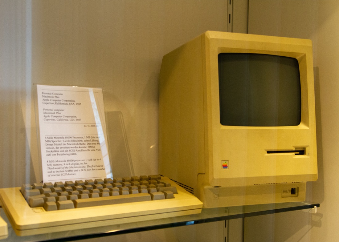
Macintosh Plus — photo by Maksym Kozlenko, CC BY-SA 4.0 (Wikimedia Commons).
Identification
| Model | Year | CPU | Note |
|---|---|---|---|
| 128K / 512K | 1984 | 68000 @ 8 MHz | the founders, soldered RAM |
| Plus | 1986 | 68000 | SCSI, expandable SIMM RAM |
| SE / SE/30 | 1987-89 | 68000 / 68030 | SE/30 = the most powerful compact, highly prized |
| Classic / Classic II | 1990-91 | 68000/030 | budget end of the line |
Repair (technician)
CRT + analog board = high voltage
The compact Mac is an all-in-one: the CRT, EHT and analog board (PSU + deflection + video) are inside. Discharge the EHT and follow CRT safety before any work.
Leaking PRAM battery (½ AA 3.6 V)
The soldered/holder PRAM battery leaks and eats the logic board (especially the SE/30). Remove it right away, clean/neutralize, repair traces → backup batteries.
- Recap the analog board: dried caps → screen folded to a line, "singing flyback", won't power on → Recap (community-documented analog kits).
- Recap the logic board (SE/30, Classic II): leaking SMD caps → dead sound, checkerboard, "simasimac" → a full recap + cleaning fixes most "dead Macs".
- Floppy drive (400/800K/SWIM 1.44 MB): mechanism / lubrication → service; emulators (Floppy Emu) common.
- Flyback: whine / unstable image → tired component (rare, hard to replace).
Step-by-step disassembly procedures ✅
1 procedures transcribed from the iFixit guides, with difficulty and estimated time.
| Procedure | Difficulty | Time |
|---|---|---|
| Macintosh Classic disassembly | Moderate | 30 minutes |
Macintosh Classic disassembly
The Macintosh Classic is a computer mounted in a simple way but with two different types of screws (Torks and Philips) put in the most unattainable places. — Templates : Model Number: M0420 and M1240
- Turn the Mac so the screen is face-down
- Put a cloth under the screen to not scratch the screen.
- Unscrew the four Torx screws.
- Two screws are on the bottom side near the ports, the other two are Hidden in the handle.
- WARNING, IF YOU COME INTO CONTACT WITH THE DISCHARGE FROM THE CRT YOU RISK DYING, We recommend looking for a tutorial on YouTube
- Connect a flat screwdriver to the CRT ground cable (black cable attached to the screw) with an alligator cable.
- Slowly push the screwdriver under the red suction cup connected to the CRT and touch the metal part with the screwdriver.
- The motherboard has no screws, so it can be removed by pulling upwards.
- Make sure to disconnect all cables.
- Remove the four screws and pay attention to the two hidden screws.
- The Floppy lock and Disk go away easily.
- WARNING - The POWER SUPPLY may still contain current inside it. Do not touch any capacitors on the power supply
- Unscrew the two screws that secure it to the chassis and remove the connected cables.
- To remove the Chassis you must use the same Torx 15 screwdriver as the handle.
- Unscrew the four screws and the Chassis can be removed.
- CAUTION: The cathode ray tube is under pressure, avoid scratching or breaking it.
- To remove the CRT, simply unscrew the four screws placed at the corners.
Source, licence and scope
iFixit guides, under Creative Commons BY-NC-SA — attribution, non-commercial, share-alike. Only the text is reproduced; the step photos stay on iFixit. ⚠️ These guides target the model named in the title: on another revision, the screws and the order of removal may differ.
Procedure — a dead computer, step by step ✅
There is a CRT inside this machine
The tube holds its charge with the machine unplugged, and on these all-in-ones the analogue board sits right where your hands go. Discharge it, or work on the logic board out of the case. → CRT safety
What this adds
Ordered for a home computer: what kills these is its power supply, its battery, its capacitors, its socketed RAM and its keyboard — roughly in that order, and well before the CPU. → PCB diagnosis
1. The power supply — measured before it is plugged in. This is the one step not to swap around. On a machine of this age a supply does not simply stop: a 5 V regulator that fails high puts 7, 9, 12 V onto the bus and takes the RAM and the custom chips with it. Measure every rail off the machine, under a dummy load if you can, and only then plug it in.
2. The battery — before anything else. This page documents a cell that leaks — check on the page whether your model is one of the affected ones, several of these pages cover a whole range. Its electrolyte eats the copper underneath and keeps eating while the machine sits in a cupboard, so it comes out first, before any diagnosis. Neutralise, clean, then check continuity on the tracks around it — a machine that no longer boots after storage is very often this and nothing else. → Backup batteries
3. Capacitors. Recap is the default on these machines, not a last resort — and on the supply first, since that is what protects everything else. → Recap
4. RAM, on its sockets. These machines were built to be repaired: the RAM, and often the logic, sit in sockets. Reseat everything first — thirty years of oxide is a classic no-boot. Then swap chips: a bad RAM chip usually gives a repeatable pattern of garbage or a screen frozen at a fixed character.
5. The keyboard. A console does not have one; a computer's is a wear part. A membrane keyboard fails as whole dead rows or columns — that is the membrane, not the machine. A mechanical one wants its contacts cleaning, not replacing. Check this page: the failure mode is often documented per model.
6. Storage — tape or disk. Both often come down to the same things: a dirty head, and for tape the azimuth and a belt turned to tar. ⚠️ On the floppy side, check whether the mechanism actually has a belt before looking for one: many do, but some drives are direct drive, and hunting a belt that isn't there means stripping a drive for nothing. A machine that boots but loads nothing is a drive fault, not a logic fault — do not go looking on the board for it.
7. Video output. RF, composite, RGB or a dedicated monitor, depending on the machine (see Identification). Test with something else before you conclude: a period modulator and a modern TV disagree far more often than either is broken.
8. Still nothing. Now the logic: rails on the board, reset, clock, bus. → PCB diagnosis
Common faults
| Symptom | Likely cause | Lead |
|---|---|---|
| Corrosion / dead sound / "simasimac" | SMD logic-board caps (SE/30) | Recap + clean |
| Screen folded to a line / no power | analog-board caps | Analog recap |
| Corrosion near the battery | leaking PRAM | Remove, neutralize, repair |
| Floppy not read | mechanism / SWIM | Service / Floppy Emu |
Modernisation & mods — what to buy, how
Leaking PRAM battery + CRT high voltage
Remove the PRAM battery without delay (it leaks and eats the board — SE/30 in particular) → clean/neutralize, repair traces. The recap targets the logic board (SE/30, Classic II) and the analog board (community kits). ⚠️ The compact Mac has a CRT: lingering high voltage (flyback) → discharge the tube before opening → CRT safety.
Modern storage - Floppy Emu (BMOW) 🟢: emulates the 400/800 KB and 1.44 MB drives and the HD20 hard disk from an SD card (external box) → direct boot, no more tired floppies. The flagship compact-Mac mod. - BlueSCSI / SCSI2SD 🟢 (Plus, SE, SE/30…): an SD card as a SCSI hard disk; PiSCSI/RaSCSI (Raspberry Pi) 🟡 adds disks, networking, virtual CDs. - ROM-inator 🟡 (SE/Plus): a replacement ROM (socketed) with RAM-disk/HD20 boot.
Video / display - Integrated 9″ B&W screen: no "color mod". On the SE/30 (030 PDS slot) you can add a video/Ethernet card for an external monitor and networking.
Reliability: recap 🟠 (logic + analog board); battery removal 🟡.
- 030/040 accelerators and RAM upgrades 🟠 for slotted models.
⚠️ Do not host ROMs/System — method only.
Archived technical documentation ✅
Manufacturer documentation archived locally: schematics, block diagrams, expected voltages, parts lists. The reference when a symptom matches no known fault.
- Macintosh port pinouts — PDF
- Macintosh IIvx / IIvi / Performa 600 — PDF
- Macintosh Plus — PDF
- Macintosh Classic — PDF
- Macintosh Classic II — PDF
- Macintosh II — PDF
- Macintosh IIcx / IIci / Quadra 700 — one Service Source covering all three machines — PDF
- Macintosh IIsi — PDF
- Macintosh LC — PDF
Status
Manufacturer documents kept for preservation (machines out of production for decades), with no explicit licence — the same position as for the cabinet manuals already archived here.
See also
- Apple II (Apple's 8-bit line) · CRT safety · Backup batteries · Recap.
Sources & attribution
- Photo Macintosh Plus — Maksym Kozlenko, CC BY-SA 4.0, Wikimedia Commons — https://commons.wikimedia.org/wiki/File:2019-08-04_Macintosh_Plus.jpg
- Wikipedia — Compact Macintosh / Macintosh SE/30 (68000/030, 9″ screen) — CC-BY-SA — https://en.wikipedia.org/wiki/Compact_Macintosh
- Established Mac community knowledge (logic/analog recap, PRAM battery, "simasimac") — synthesis.

Review & corrections
How this space is used
Spotted a wrong value, an outdated procedure, a chip reference that does not match your board? Say so here, with what you observed (model, board revision, serial number, measurement). Every report is cross-checked against a source before anything changes — an unverifiable correction is published as “reported by …, not cross-checked” rather than silently applied.
Reading is open to everyone; posting requires signing in with Discord. Reports from the wiki's declared reviewers are handled first; anyone else's are read too, but go through a human before anything is changed.