Tatung Einstein
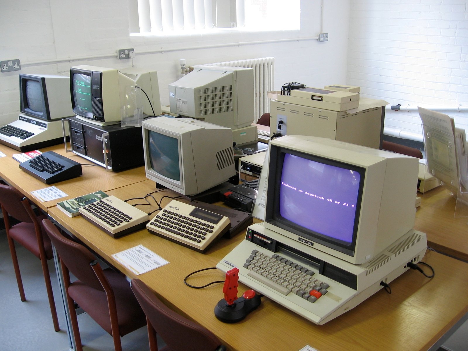
A 1984 British machine offered with one or two built-in 3″ drives where the competition was still shipping cassette decks. Good news for the technician: it is standard Zilog logic, entirely repairable with parts that are still available.
Identification
| Field | Value |
|---|---|
| Manufacturer | Tatung (UK / Taiwan) |
| Years | 1984-1986 |
| CPU | Z80 (Z8400A) @ 4 MHz — designator I001 |
| RAM | 64 KB system · 16 KB video (designators I040 and I041) |
| Sound | AY-3-8910 @ 2 MHz — designator I030 |
| Video | TMS9129 @ 10.738635 MHz — designator I038 |
| Floppy | WD1770-PH @ 8 MHz — designator I042 |
| Joysticks | ADC0844CCN (analogue conversion) — designator I050 |
| CTC | Z80 CTC (Z8430A) @ 4 MHz — designator I058 |
| Serial | μPD8251A @ 2 MHz — designator I060 |
| PIO | Z80 PIO (Z8420A) @ 4 MHz — designator I063 |
| Crystals | X001 = 10.738635 MHz · X002 = 8 MHz (system) |
| Boot | MOS in ROM; Xtal DOS, CP/M-compatible, loads from floppy |
| Monitor | external, optional (Tatung monochrome or colour) |
Designators that match the packages
I001, I030, I042… are the designators the MAME driver uses to name the chips,
and they follow the board's own scheme. They let you go straight to the right
package.
Two honest caveats: I038 (video) and I050 (converter) are only defined at the top of the driver and are not used to instantiate the chips — the mapping is stated by the driver, not demonstrated by its code. Likewise the X001 label is defined at 10.738635 MHz but the video chip receives that value literally: associating that crystal with video is a reasonable deduction, not a driver assertion.
Expected clocks — measurement table ✅
| Component | Frequency | Source |
|---|---|---|
| Z80 (I001) | 4 MHz | X002 ÷ 2 |
| Z80 PIO (I063) | 4 MHz | X002 ÷ 2 |
| Z80 CTC (I058) | 4 MHz | X002 ÷ 2 |
| CTC — channels 0/1/2 | 2 MHz | X002 ÷ 4 |
| AY-3-8910 (I030) | 2 MHz | X002 ÷ 4 |
| μPD8251A (I060) | 2 MHz | X002 ÷ 4 |
| WD1770 (I042) | 8 MHz | X002 undivided |
| TMS9129 | 10.738635 MHz | dedicated crystal |
Two diagnostic points worth knowing
The serial link is clocked by the CTC, not by the USART
CTC channels 0 and 1 supply TxC and RxC to the μPD8251A. A dead or wrong-speed serial port therefore does not necessarily accuse the USART: if the CTC stops producing its clocks, the 8251 is innocent. Check the CTC (I058) before desoldering I060.
The floppy controller runs at the full crystal
The WD1770 gets the undivided 8 MHz, unlike almost everything else on the machine. Measuring 4 MHz on its clock pin is not normal.
What MAME calls TMM9129
The driver names the video chip with the comment /* TMM9129 */ but emulates a
TMS9129. The reason for that discrepancy is not documented, and no consulted
source knows of a "TMM9129" part: neither the list of TMS9918 clones (Yamaha
V9938/V9958, Toshiba T6950 and T7937A) nor any datasheet.
If you open a machine, the marking you read on the package is more reliable than this page — and we would like to know it.
The models
| Model | Year | Note |
|---|---|---|
| Einstein (TC-01) | 1984 | the model documented here |
| Einstein 256 | 1986 | ⚠️ different hardware — see below |
The Einstein 256 is not an improved TC-01
Do not carry this page's values over to a 256. Compared with the TC-01 it does not have the I063 PIO, the TMS9129, the ADC0844 converter, or drives 2 and 3, and it loses the pipe interface and the user port. Its video is a V9938 at 21.477272 MHz and its interrupt chain is different.
The driver also lists interrupt priorities and the VAMP interface among its TODOs, suspecting the latter was "probably never used".
Floppy drives
The machine's drive-select latch handles up to four units (an external latch does that job: the WD1770 has no select output).
| Unit | Fitted from the factory |
|---|---|
| 0 and 1 | 3″ single-sided |
| 2 and 3 | 5.25″ quad density |
The other accepted formats are 3″ double-sided double density, 5.25″ single-sided quad density, and 3.5″ single and double density.
Sources disagree on the 3″ drive — and no belt is documented
Who made the drive is not settled: MAME fits a TEAC FD-30A on units 0 and 1, while Wikipedia attributes the built-in drives to Hitachi. We do not resolve this.
What is clear is that no consulted source documents belt drive on this machine — the FD-30A is described as direct drive and single-sided. Do not transpose the belt diagnosis from the Amstrad CPC here: these two machines share the 3″ medium (scarce CF-2 disks, the case for a Gotek), not the mechanism.
Common faults
| Symptom | Likely cause | Lead |
|---|---|---|
| Won't boot | Z80 (I001) or the X002 8 MHz crystal | Check 4 MHz after division |
| No picture | TMS9129 (I038) or its crystal | Crystal separate from the 8 MHz |
| No sound | AY-3-8910 (I030) | Expected at 2 MHz |
| Dead / wrong-speed serial | ⚠️ the CTC (I058), not necessarily the USART | See the note above |
| Floppy unreadable | WD1770 (I042) or the mechanism | Expected clock: 8 MHz |
| Analogue joysticks dead | ADC0844 (I050) | Dedicated conversion circuit |
Repair (technician)
- Entirely standard logic: Z80, PIO, CTC, AY-3-8910, WD1770 and 8251 are all still findable, new or salvaged. No insurmountable custom.
- Two distinct crystals: don't chase video faults on the 8 MHz — video has its own.
- Z80 interrupt chain, in order: keyboard → CTC → ADC converter → PIO → fire button. A peripheral stuck in interrupt can freeze the ones after it in that order. ⚠️ Caveat: the MAME driver lists interrupt priorities among its TODOs — this is the order it applies, not an order it guarantees matches the hardware.
- Recap: a 1984 machine, the supply electrolytics are their age.
→ Methods: PCB diagnosis · Recap
Procedure — a dead computer, step by step ✅
What this adds
Ordered for a home computer: what kills these is its power supply, its battery, its capacitors, its socketed RAM and its keyboard — roughly in that order, and well before the CPU. → PCB diagnosis
1. The power supply — measured before it is plugged in. This is the one step not to swap around. On a machine of this age a supply does not simply stop: a 5 V regulator that fails high puts 7, 9, 12 V onto the bus and takes the RAM and the custom chips with it. Measure every rail off the machine, under a dummy load if you can, and only then plug it in.
2. The battery, if it has one. Any RTC or backup cell soldered to a board is a future leak. If yours has one and it has never been changed, take it out before it takes the tracks with it. → Backup batteries
3. Capacitors. Recap is the default on these machines, not a last resort — and on the supply first, since that is what protects everything else. → Recap
4. RAM, on its sockets. These machines were built to be repaired: the RAM, and often the logic, sit in sockets. Reseat everything first — thirty years of oxide is a classic no-boot. Then swap chips: a bad RAM chip usually gives a repeatable pattern of garbage or a screen frozen at a fixed character.
5. The keyboard. A console does not have one; a computer's is a wear part. A membrane keyboard fails as whole dead rows or columns — that is the membrane, not the machine. A mechanical one wants its contacts cleaning, not replacing. Check this page: the failure mode is often documented per model.
6. Storage — tape or disk. Both often come down to the same things: a dirty head, and for tape the azimuth and a belt turned to tar. ⚠️ On the floppy side, check whether the mechanism actually has a belt before looking for one: many do, but some drives are direct drive, and hunting a belt that isn't there means stripping a drive for nothing. A machine that boots but loads nothing is a drive fault, not a logic fault — do not go looking on the board for it.
7. Video output. RF, composite, RGB or a dedicated monitor, depending on the machine (see Identification). Test with something else before you conclude: a period modulator and a modern TV disagree far more often than either is broken.
8. Still nothing. Now the logic: rails on the board, reset, clock, bus. → PCB diagnosis
Modernisation & mods
- ⚠️ Do not host ROMs or disk images — method only.
Photos / assets
(To take: the motherboard with the designators legible, the two crystals X001 and X002, the 3″ drive — and the exact marking read on the video chip, which would settle the TMM/TMS question.)
Sources & attribution
Text (synthesis; sources listed for attribution):
- MAME —
src/mame/tatung/einstein.cpp(GPL-2.0+, driver by Kevin Thacker, Dirk Best, Phill Harvey-Smith and Nigel Barnes; thanks to Chris Coxall and Andrew Dunipace): the X001 = 10.738635 MHz and X002 = 8 MHz crystals; the Z80 (Z8400A, I001), PIO (Z8420A, I063) and CTC (Z8430A, I058) at X002 ÷ 2; the CTC's three channels, the AY-3-8910 (I030) and the μPD8251A (I060) at X002 ÷ 4, with channels 0 and 1 wired to TxC and RxC of the 8251; the WD1770-PH (I042) at X002 undivided; the TMS9129 at 10.738635 MHz, named in a comment as/* TMM9129 */— a discrepancy the driver does not explain; the 16 KB of VRAM "provided by IC i040 and i041" and the 64 KB of system RAM; the four drive connectors with 3″ single-sided (TEAC FD-30A) on units 0 and 1 and 5.25″ QD on units 2 and 3; the interrupt chain keyboard → CTC → ADC → PIO → fire; the 8 KB BIOS "called MOS"; the Einstein 256 differences (V9938 at 21.477272 MHz, removal of the PIO, the TMS9129, the ADC and drives 2/3); and the driver's TODOs: interrupt priorities and the VAMP interface "probably never used" — https://github.com/mamedev/mame/blob/master/src/mame/tatung/einstein.cpp - Wikipedia — Tatung Einstein (CC-BY-SA): "an option for one or two built-in three-inch floppy disk drives manufactured by Hitachi" — a drive attribution that diverges from MAME's, flagged on this page and left unresolved; booting into MOS (Machine Operating System) and Xtal DOS, "a CP/M-compatible operating system", loaded from floppy; 64 KB system / 16 KB video; and the Tatung monitor sold as an option, hence external — https://en.wikipedia.org/wiki/Tatung_Einstein
Image:
-
einstein-machine.jpg— Marcin Wichary, CC BY 2.0 — https://commons.wikimedia.org/wiki/File:Tatung_Einstein_and_NewBrain.jpg

Review & corrections
How this space is used
Spotted a wrong value, an outdated procedure, a chip reference that does not match your board? Say so here, with what you observed (model, board revision, serial number, measurement). Every report is cross-checked against a source before anything changes — an unverifiable correction is published as “reported by …, not cross-checked” rather than silently applied.
Reading is open to everyone; posting requires signing in with Discord. Reports from the wiki's declared reviewers are handled first; anyone else's are read too, but go through a human before anything is changed.