Amstrad GX4000
Amstrad's console (September 1990, Europe only): really a CPC Plus without a keyboard, in a console shell with games on cartridge. A late release (8-bit in the 16-bit era), a thin library and pricey carts made it a commercial failure (< 15,000 units), discontinued as early as 1991.
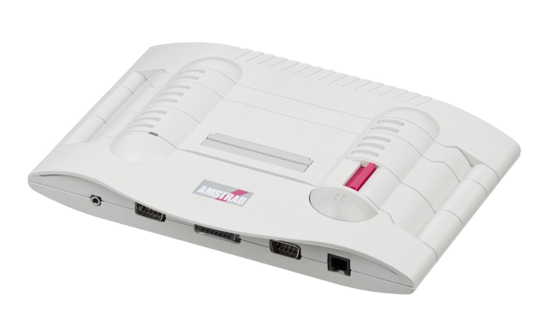
Amstrad GX4000 — photo by Evan-Amos, domaine public (Wikimedia Commons).
Identification
| Field | Value |
|---|---|
| Manufacturer | Amstrad |
| Released | September 1990 — UK, France, Spain, Italy |
| Price | £99.99 / Fr 990 (games ~£25 / cartridge) |
| Hardware base | CPC Plus range (464 Plus / 6128 Plus) |
| Media | ROM cartridge (up to 512 KiB) |
| Region / video | PAL 50 Hz — RGB SCART + composite + RF |
| Bundled | Burnin' Rubber, a power pack, 2 controllers |
Architecture (detail)
| Block | Chip | Clock | Role |
|---|---|---|---|
| CPU | Zilog Z80A | 4 MHz | 8-bit CPU, identical to the CPC |
| Graphics | "Plus" ASIC | 16 hardware sprites 16×16 (×2/×4 magnify), hardware scrolling, 4096-colour palette (32 on-screen) | |
| Sound | General Instrument AY-3-8912 (3-channel PSG, stereo) | + DMA sound (lists handled by the ASIC) | |
| Memory | 64 KiB RAM | of which 16 KiB is VRAM |
Video modes (inherited from the CPC): 160×200 (16 c.), 320×200 (4 c.), 640×200 (2 c.).
The GX4000 is hardware-identical to a CPC Plus: same cartridges as the CPC 464 Plus / 6128 Plus (a CPC Plus reads GX4000 carts and vice-versa). What the Plus range added over the original CPC is the sprites, hardware scroll, 4096 palette and DMA sound — but with no keyboard and no tape/disk drive, the machine can load only from cartridge, which throttled the software supply.
Why it failed (preservation context)
- A library of only ~27 games, often unambitious CPC ports.
- £25 cartridges against CPC cassettes at £3.99 → buyers balked.
- An 8-bit machine launched in 1990, against 16-bit Mega Drive / Super Famicom.
- Slow manufacturing, patchy distribution, weak marketing.
Common faults
| Symptom | Likely cause | Lead |
|---|---|---|
| Cartridge not read / crash | oxidised cart contacts | Clean the connector (isopropyl alcohol) |
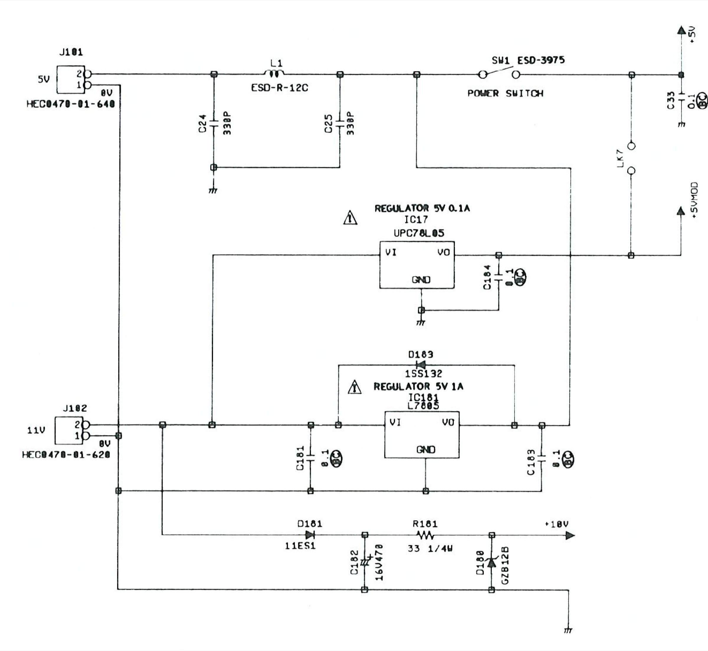
| No power | external power pack dead (original brick) | Test/replace the PSU (check voltage/polarity) |
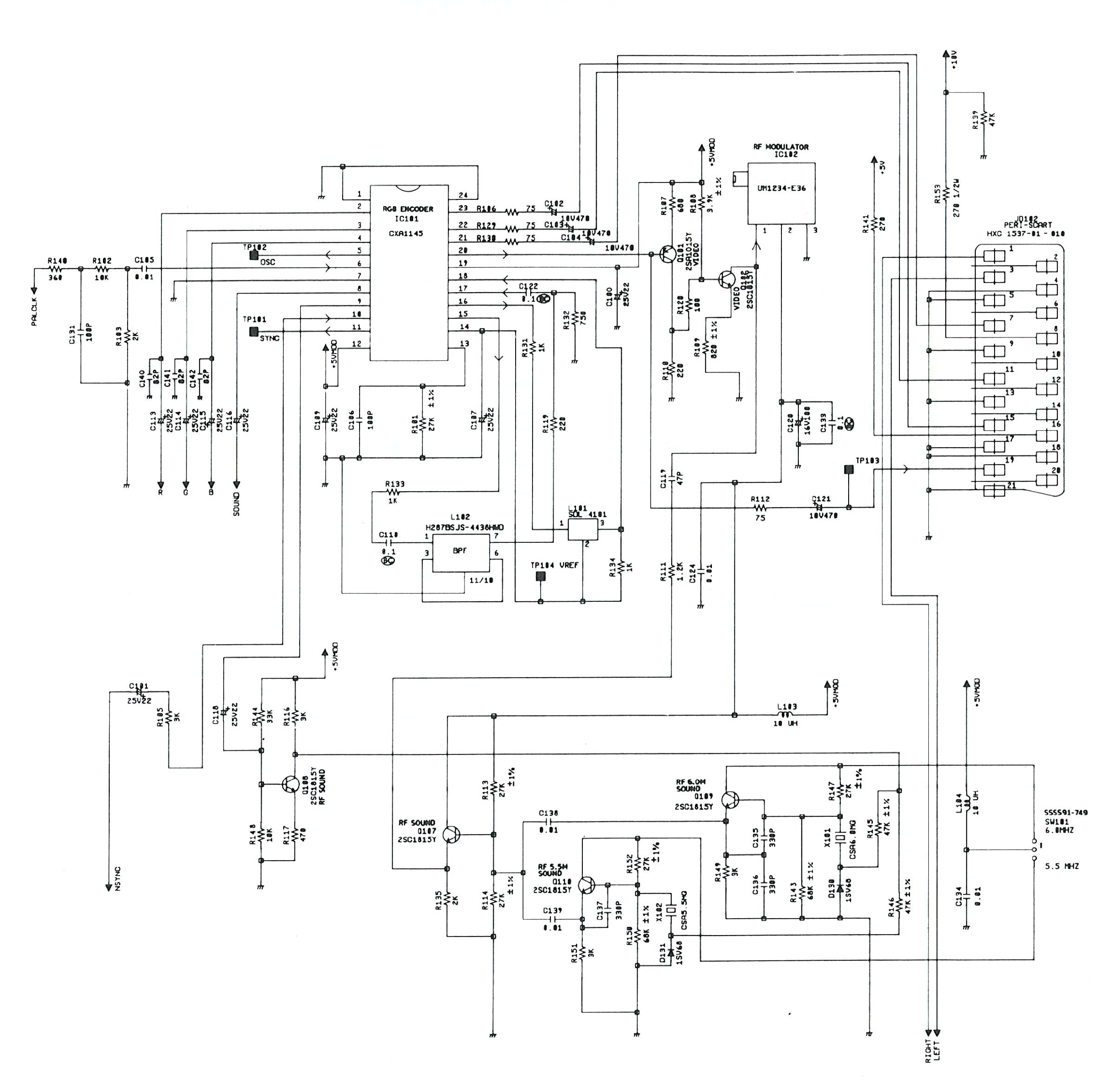
| No picture | RGB SCART cable/output, or ASIC | Check the SCART cable and the TV input |
| Degraded picture/sound | ageing capacitors | Targeted recap of the affected stage |
Procedure — a dead console, step by step ✅
What this adds
Ordered for a console, not for an arcade board: what kills these is almost never the CPU. It is, in real order, the power supply, the capacitors, the drive or the cartridge slot, and only then the logic. → PCB diagnosis
1. The power supply. Two cases, depending on the machine. External brick: ⚠️ read the marking on the machine, next to the socket, and check the adapter against it — voltage and polarity. A centre-negative machine fed centre-positive loses its fuse, sometimes its regulator; do not trust a third-party label or a generic tip. Internal supply (the machine plugs straight into the wall): mains is inside the shell. Unplug, wait, and confirm the large capacitors are discharged before touching the board. Either way, measure under load: a failing supply holds its voltage until it is asked for current.
2. The fuse. Many of these machines have one right behind the socket — it is the part designed to die. Test it in continuity, out of circuit. A fuse that blows again is a short, not a fuse problem.
3. Capacitors. On most machines of this age this is the default suspect rather than a last resort — leaking SMD electrolytics eat the tracks underneath before they give any other sign. ⚠️ Not all of them are like that: some carry very few and are not recapped on principle. Read what this page says about it before reaching for the iron. → Recap
4. The cartridge connector. Cartridge contacts with isopropyl alcohol, never an abrasive eraser: it takes the gold plating off and the problem comes back worse. On the machine side, inspect the slot pins — splayed, bent or oxidised — and check continuity between slot and board.
5. Video output. Isolate the machine from the display: another cable, another TV, another input. A sizeable share of "dead consoles" are a dead cable, or a display that will not lock onto what this machine outputs — see the video section of this page for what that is.
6. Still nothing. Now, and only now, the logic: rails on the board, reset, clock, bus. → PCB diagnosis
Mods & repair — what to buy, how
- Factory RGB SCART output 🟢: clean RGB with no mod (a big edge over the era's consoles) → an Amstrad SCART cable then OSSC/RetroTINK/RGB2HDMI.
- C4CPC flashcart 🟢: an SD cart loading Plus / GX4000 games in the cartridge port — plug-and-play, ideal for preservation.
- Power: the GX4000 is fussy about its PSU → check/replace with a stable supply (a weak supply = crashes).
- Controller: stock pads get flaky → refresh the contacts or use an adapter (the port is an Atari/joystick type — connect with care).
- Cartridge contact cleaning + recap if the video/sound stage is tired.
- ⚠️ Do not host ROMs/cartridges — we describe the method, not the protected content.
Photos / assets
(To add: GX4000 console, controller, cartridge, motherboard.)
Advanced repair — cross-cutting methods
Archived technical documentation ✅
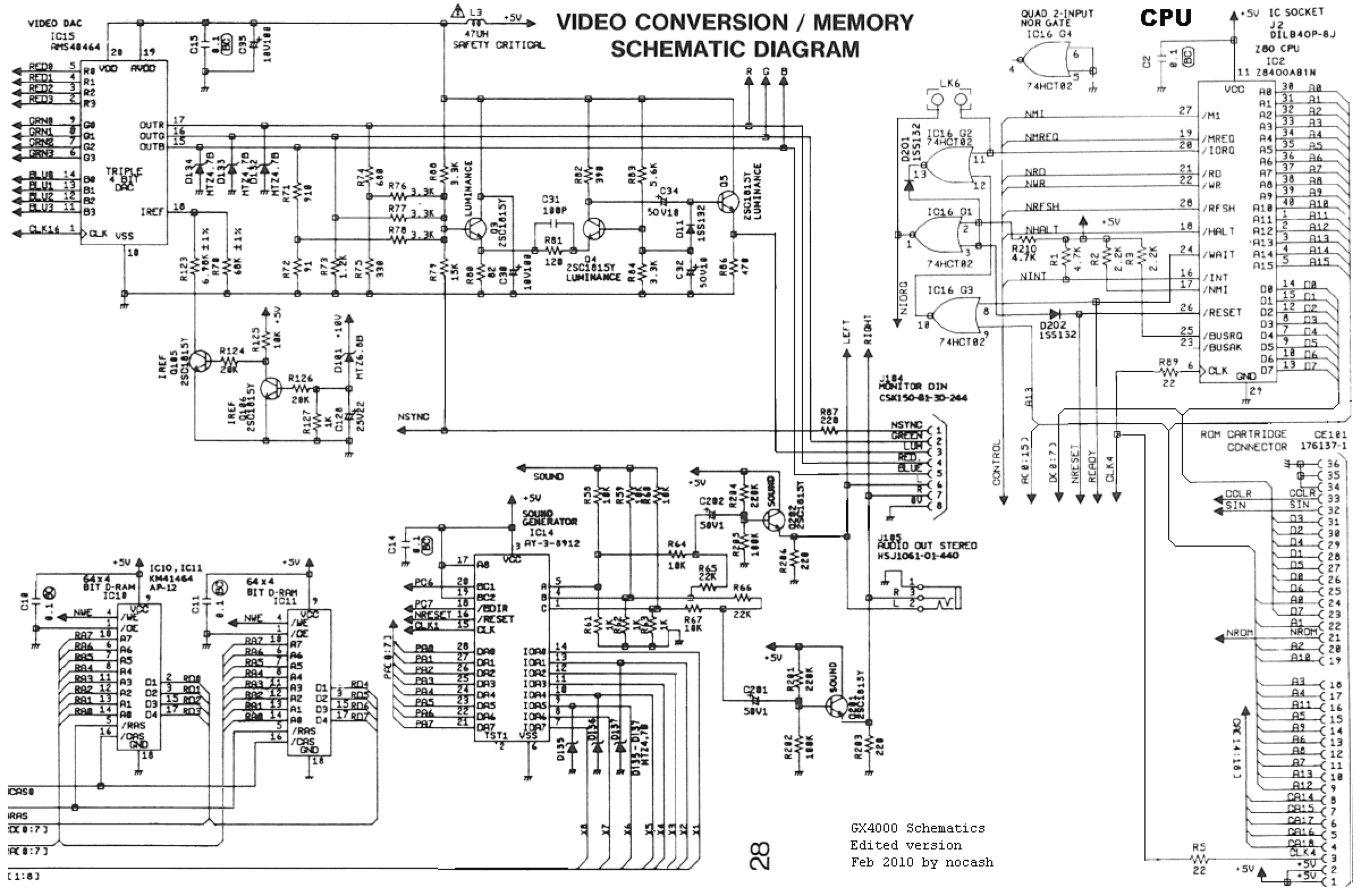
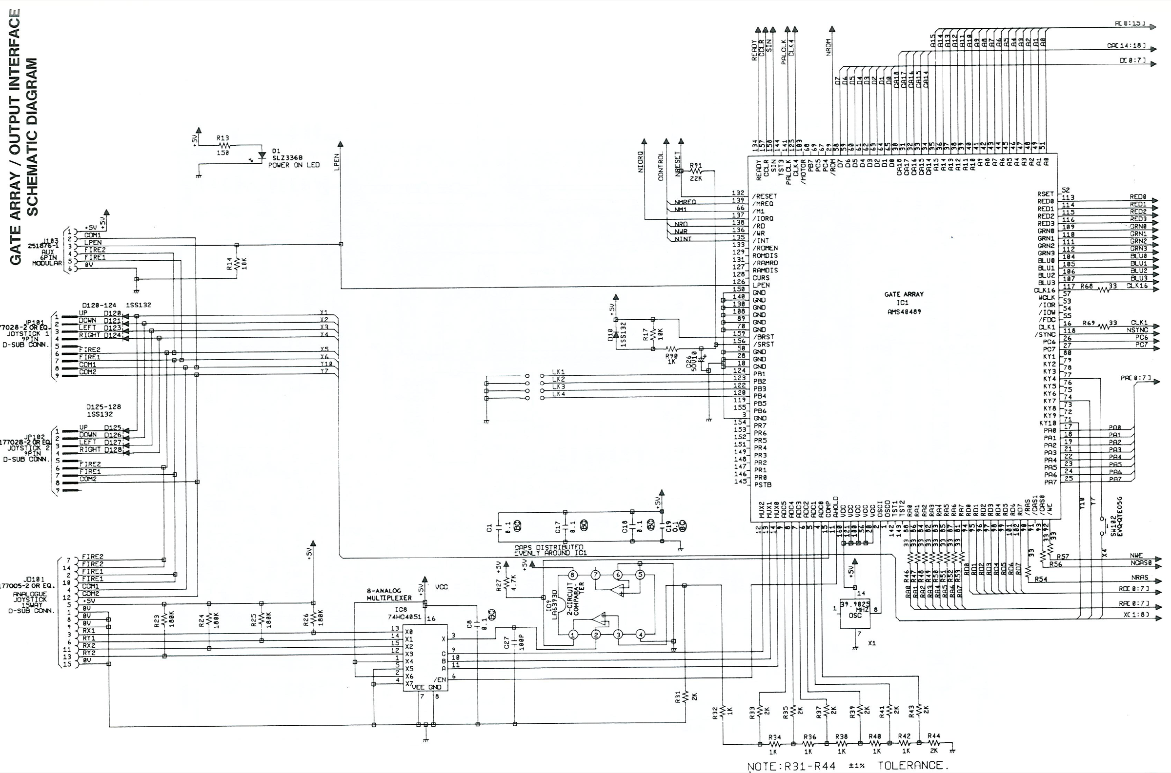
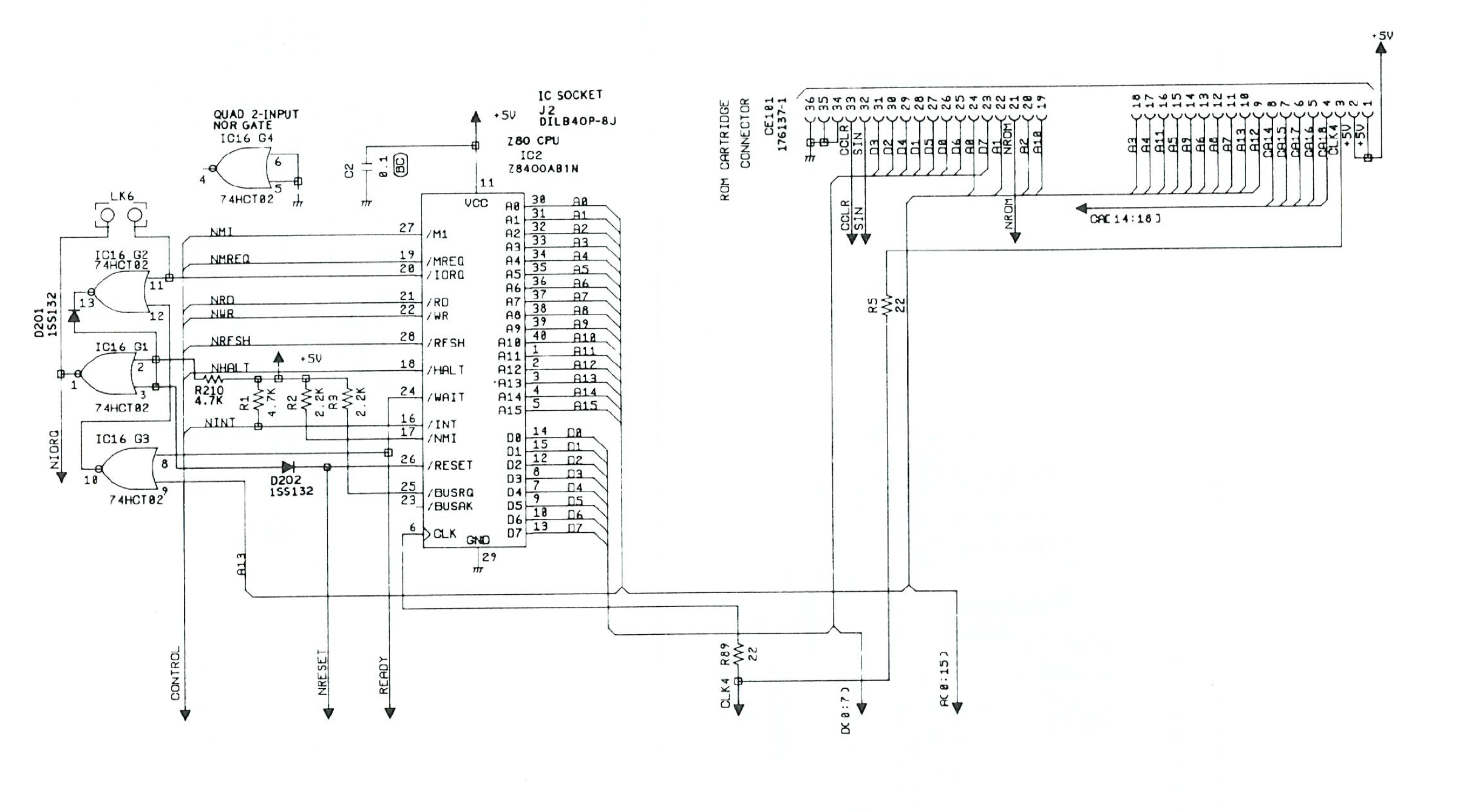
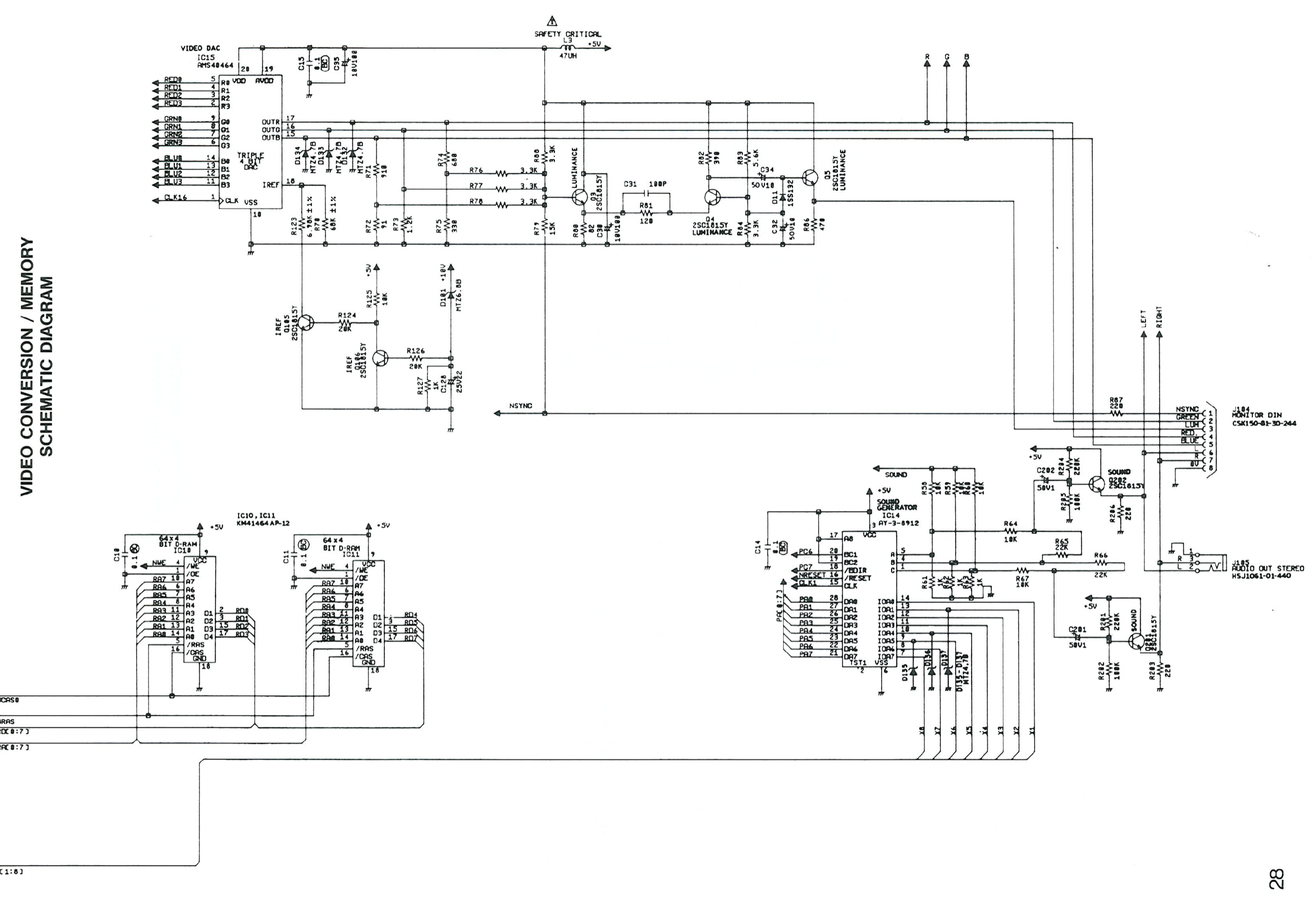
Manufacturer documentation archived locally: schematics, block diagrams, expected voltages, parts lists. The reference when a symptom matches no known fault.
- GX4000 — PDF
Status
Manufacturer documents kept for preservation (machines out of production for decades), with no explicit licence — the same position as for the cabinet manuals already archived here.
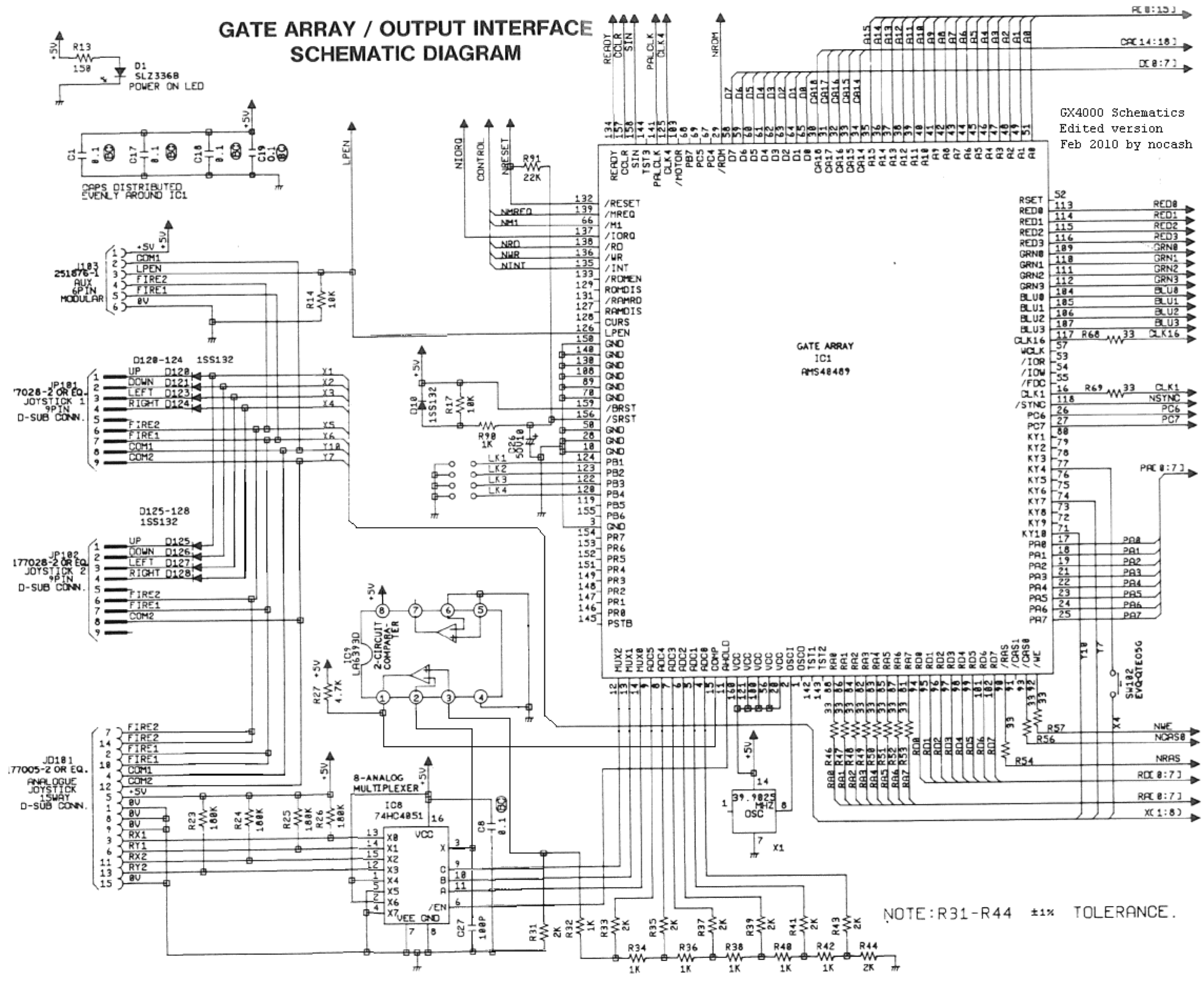
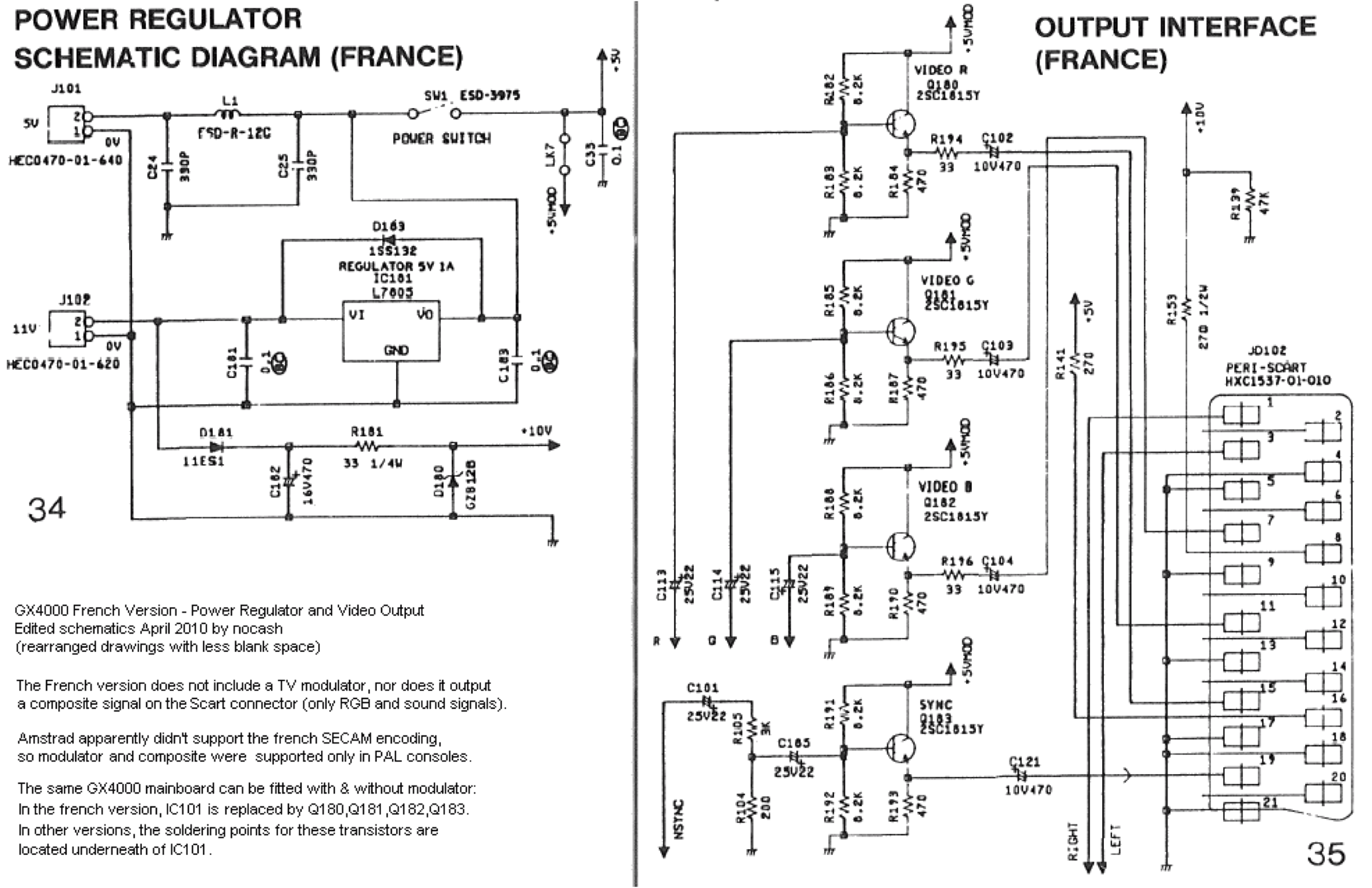
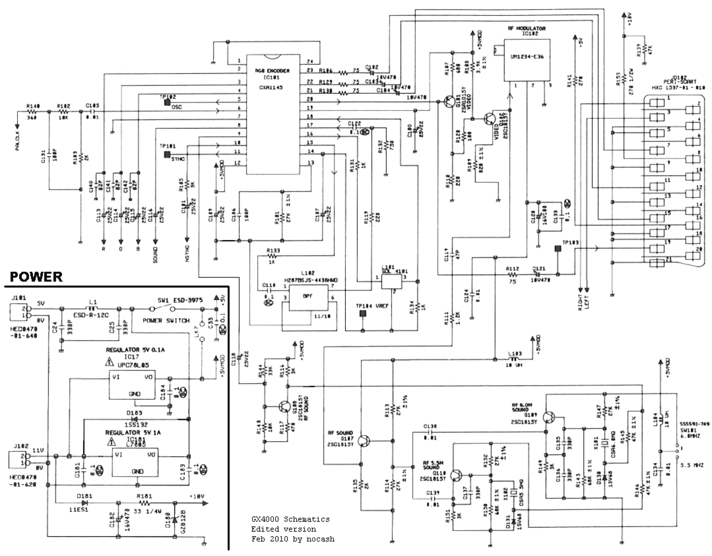
GX4000 schematics ✅
ASIC, CPU, memory/video, power and RGB — plus the French variant.
Provenance
Schematics of undocumented origin in the collection they came from: no author and no licence is stated there.
Sources & attribution
-
Photo Amstrad GX4000 — Evan-Amos, domaine public, Wikimedia Commons — https://commons.wikimedia.org/wiki/File:Amstrad-GX4000-Console-FL.jpg
-
Wikipedia — Amstrad GX4000 (specs, Plus ASIC, library, commercial failure) — CC-BY-SA — https://en.wikipedia.org/wiki/Amstrad_GX4000
- CPCWiki — GX4000 / Plus range — to reference — https://www.cpcwiki.eu/index.php/GX4000

Review & corrections
How this space is used
Spotted a wrong value, an outdated procedure, a chip reference that does not match your board? Say so here, with what you observed (model, board revision, serial number, measurement). Every report is cross-checked against a source before anything changes — an unverifiable correction is published as “reported by …, not cross-checked” rather than silently applied.
Reading is open to everyone; posting requires signing in with Discord. Reports from the wiki's declared reviewers are handled first; anyone else's are read too, but go through a human before anything is changed.