Amstrad CPC Plus (464 Plus / 6128 Plus)
The 1990 CPC redesign: same Z80A but a "Plus" ASIC adding hardware sprites, scrolling, a 4096-colour palette and DMA sound. Two models — 464 Plus (tape) and 6128 Plus (3″ disk) — plus the keyboard-less console version, the GX4000. Backward-compatible with the original CPC software library.
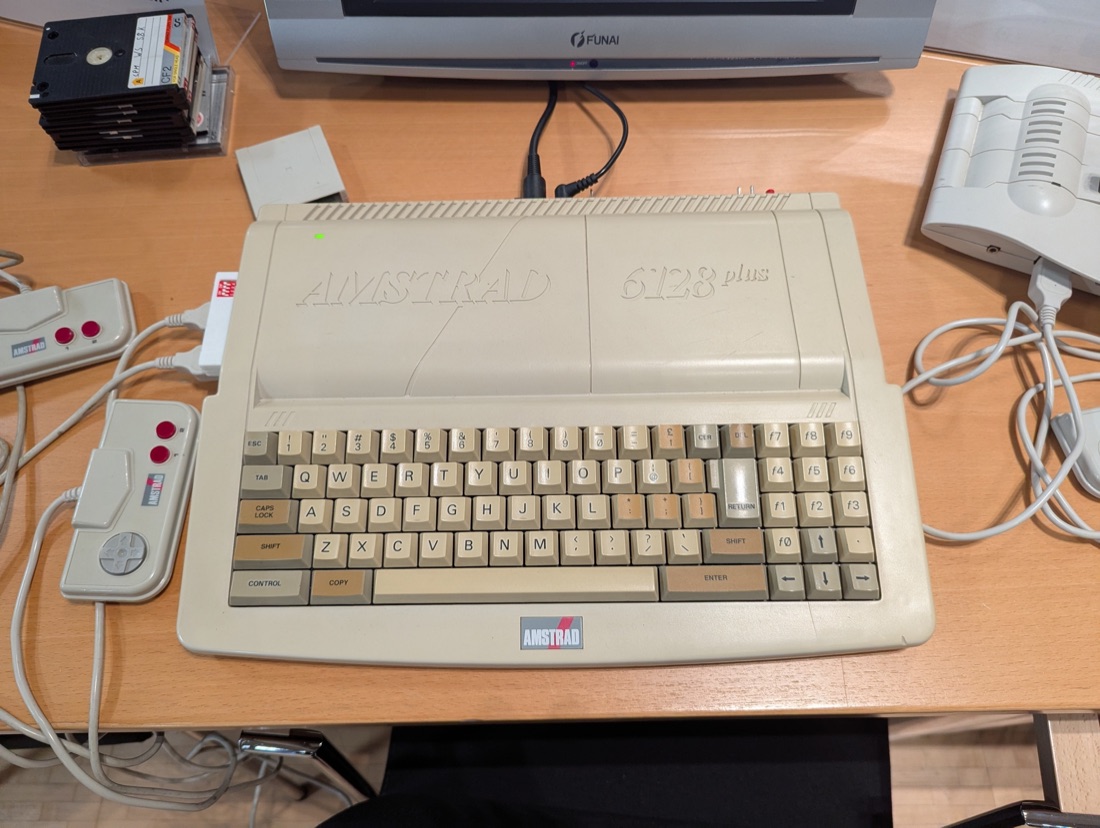
Amstrad 6128 Plus — photo by Thomas Vogt, CC BY 4.0 (Wikimedia Commons).
Identification
| Field | Value |
|---|---|
| Manufacturer | Amstrad |
| Released | 1990 (Europe) |
| Models | 464 Plus (tape + cartridge) · 6128 Plus (3″ disk + cartridge) |
| Media | Tape or 3″ disk per model, + ROM cartridge (≤ 4 Mbit) |
| Base | CPC range; derived console = GX4000 |
| Video | RGB on DIN (→ SCART by wiring), original CTM monitor |
Architecture (detail)
| Block | Chip | Clock | Role |
|---|---|---|---|
| CPU | Zilog Z80A | 4 MHz | identical to the original CPC |
| Graphics | "Plus" ASIC | 16 sprites 16×16 (magnifiable), hardware scroll, 4096 palette (16 background + 16 sprite on-screen) | |
| Sound | General Instrument AY-3-8912 (3-channel PSG) | + DMA sound (lower CPU load) | |
| Memory | 64 KiB (464 Plus) / 128 KiB (6128 Plus) |
The CPC Plus runs the CPC library (tape/disk) and Plus / GX4000 cartridges. The ASIC is locked behind an "unlock" sequence (secret register): it drives the sprites, scroll, palette and DMA sound. Games that use these features are rare — hence the heritage value of preserving the cartridges.
Repair (technician)
3″ disk drive (6128 Plus) — the No. 1 fault
The drive's rubber belt perishes over time (sticky residue) → disk won't spin / read errors. Replace the belt (measure the Ø, square section); clean the spindle pulley and the head (isopropyl alcohol). Check the anti-dust foam too.
- 3″ media: the Amsoft/Maxell format is rare and expensive; for preservation prefer a drive emulator (e.g. a Gotek with Amstrad-compatible firmware, or HxC).
- Cartridge & edge contacts: isopropyl clean if it crashes at boot.
- RGB output: the CPC Plus outputs clean RGB; wiring to SCART is a simple adapter (see RGB video mods).
- Capacitors: targeted recap if picture/sound degrade; power comes from the CTM monitor (the CPC has no internal PSU) → also check the monitor's PSU.
- Membrane keyboard: dead keys = tired membrane (replace) or a cut trace (conductive repair).
Procedure — a dead computer, step by step ✅
What this adds
Ordered for a home computer: what kills these is its power supply, its battery, its capacitors, its socketed RAM and its keyboard — roughly in that order, and well before the CPU. → PCB diagnosis
1. The power supply — measured before it is plugged in. This is the one step not to swap around. On a machine of this age a supply does not simply stop: a 5 V regulator that fails high puts 7, 9, 12 V onto the bus and takes the RAM and the custom chips with it. Measure every rail off the machine, under a dummy load if you can, and only then plug it in.
2. The battery, if it has one. Any RTC or backup cell soldered to a board is a future leak. If yours has one and it has never been changed, take it out before it takes the tracks with it. → Backup batteries
3. Capacitors. Recap is the default on these machines, not a last resort — and on the supply first, since that is what protects everything else. → Recap
4. RAM, on its sockets. These machines were built to be repaired: the RAM, and often the logic, sit in sockets. Reseat everything first — thirty years of oxide is a classic no-boot. Then swap chips: a bad RAM chip usually gives a repeatable pattern of garbage or a screen frozen at a fixed character.
5. The keyboard. A console does not have one; a computer's is a wear part. A membrane keyboard fails as whole dead rows or columns — that is the membrane, not the machine. A mechanical one wants its contacts cleaning, not replacing. Check this page: the failure mode is often documented per model.
6. Storage — tape or disk. Both often come down to the same things: a dirty head, and for tape the azimuth and a belt turned to tar. ⚠️ On the floppy side, check whether the mechanism actually has a belt before looking for one: many do, but some drives are direct drive, and hunting a belt that isn't there means stripping a drive for nothing. A machine that boots but loads nothing is a drive fault, not a logic fault — do not go looking on the board for it.
7. Video output. RF, composite, RGB or a dedicated monitor, depending on the machine (see Identification). Test with something else before you conclude: a period modulator and a modern TV disagree far more often than either is broken.
8. Still nothing. Now the logic: rails on the board, reset, clock, bus. → PCB diagnosis
Common faults
| Symptom | Likely cause | Lead |
|---|---|---|
| Disk not read (6128 Plus) | perished belt / dirty head | Replace belt, clean head |
| Nothing on power-up | monitor PSU, fuse, joints | Check monitor→board voltage |
| Cartridge ignored | contacts / ASIC unlock sequence | Clean contacts, try another cart |
| Dead keys | keyboard membrane | Replace the membrane |
| Wrong colours/sound | ASIC / caps | Recap, check the ASIC |
Mods & preservation — what to buy, how
- Gotek / HxC (6128 Plus) 🟡: a drive emulator replacing the 3″ (rare, dead belts) → DSK disk images from a USB stick. Connects to the drive's 34-pin ribbon; set DRIVE SELECT and power. The FlashFloppy firmware is recommended (CPC-format aware).
- C4CPC flashcart 🟢: an SD cart that loads Plus / GX4000 games from an SD card in the cartridge port — plug-and-play.
- RGB video 🟢: the CPC Plus outputs RGB on its connector → an adapted SCART cable (mind the Amstrad pinout/sync) then OSSC/RetroTINK. No internal mod.
- Reliability recap (power/video).
- ⚠️ Do not host ROMs/disks — method only.
Photos / assets
(To add: 464 Plus, 6128 Plus, ASIC, 3″ drive, cartridge.)
Advanced repair — cross-cutting methods
Archived technical documentation ✅
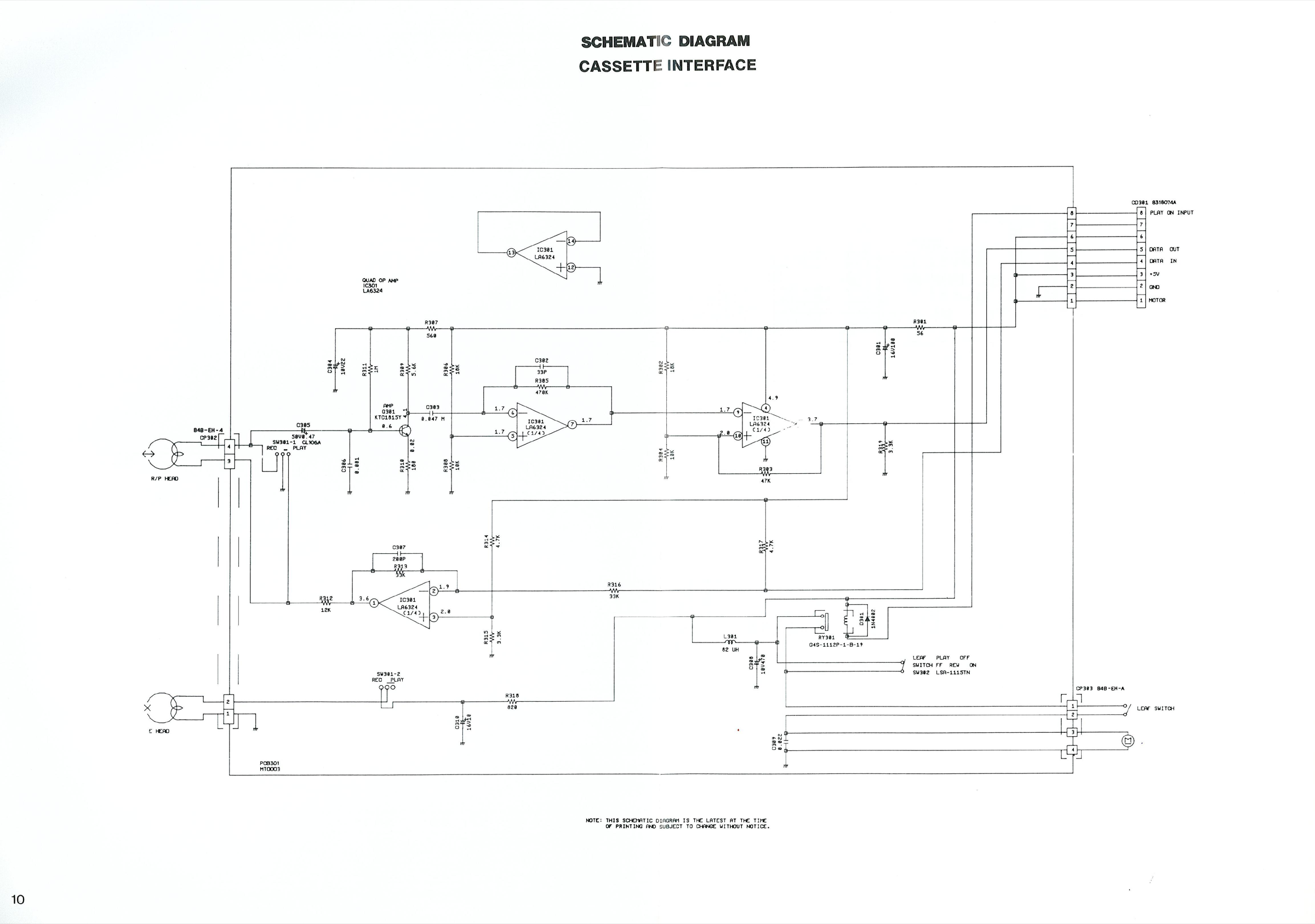
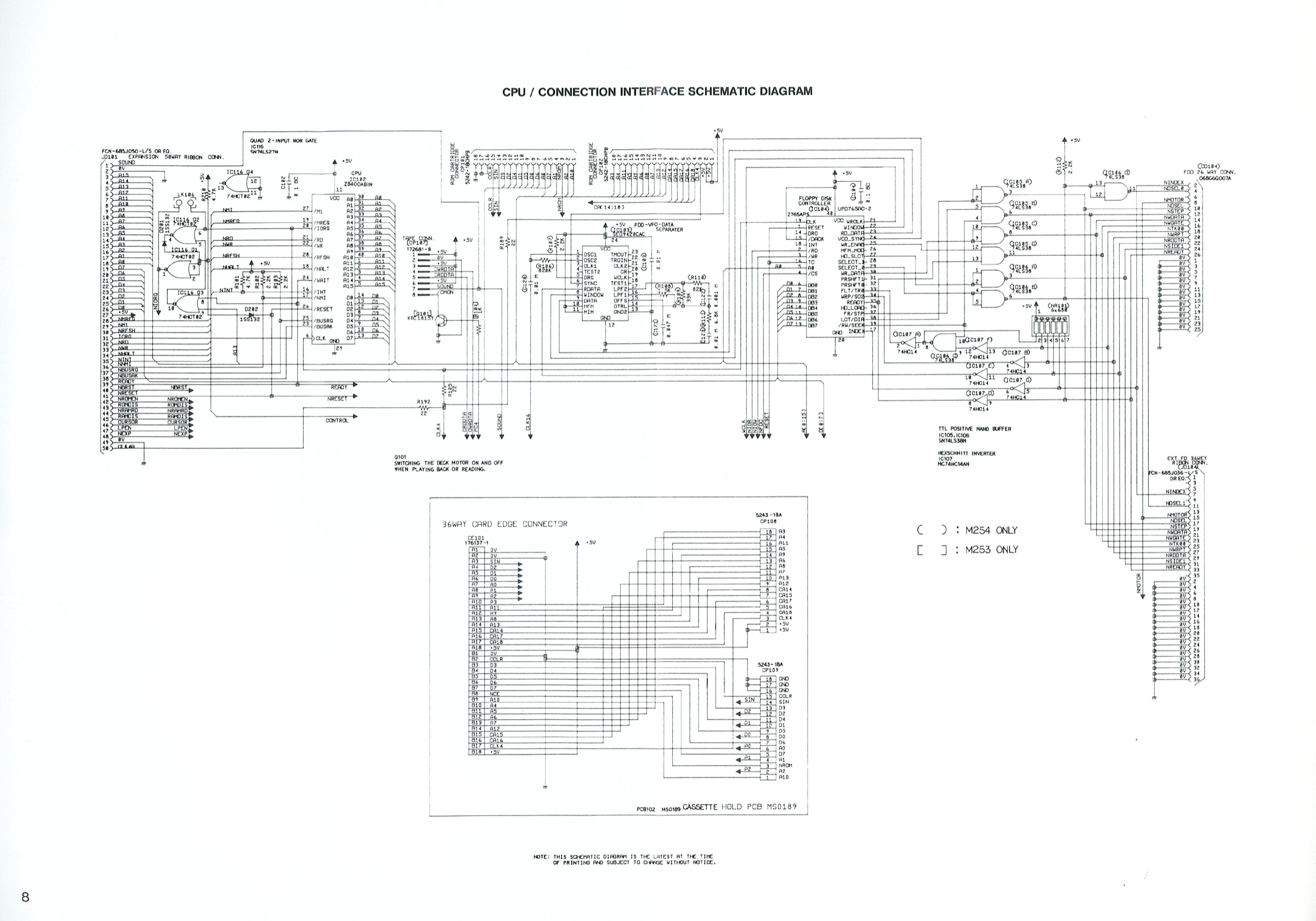
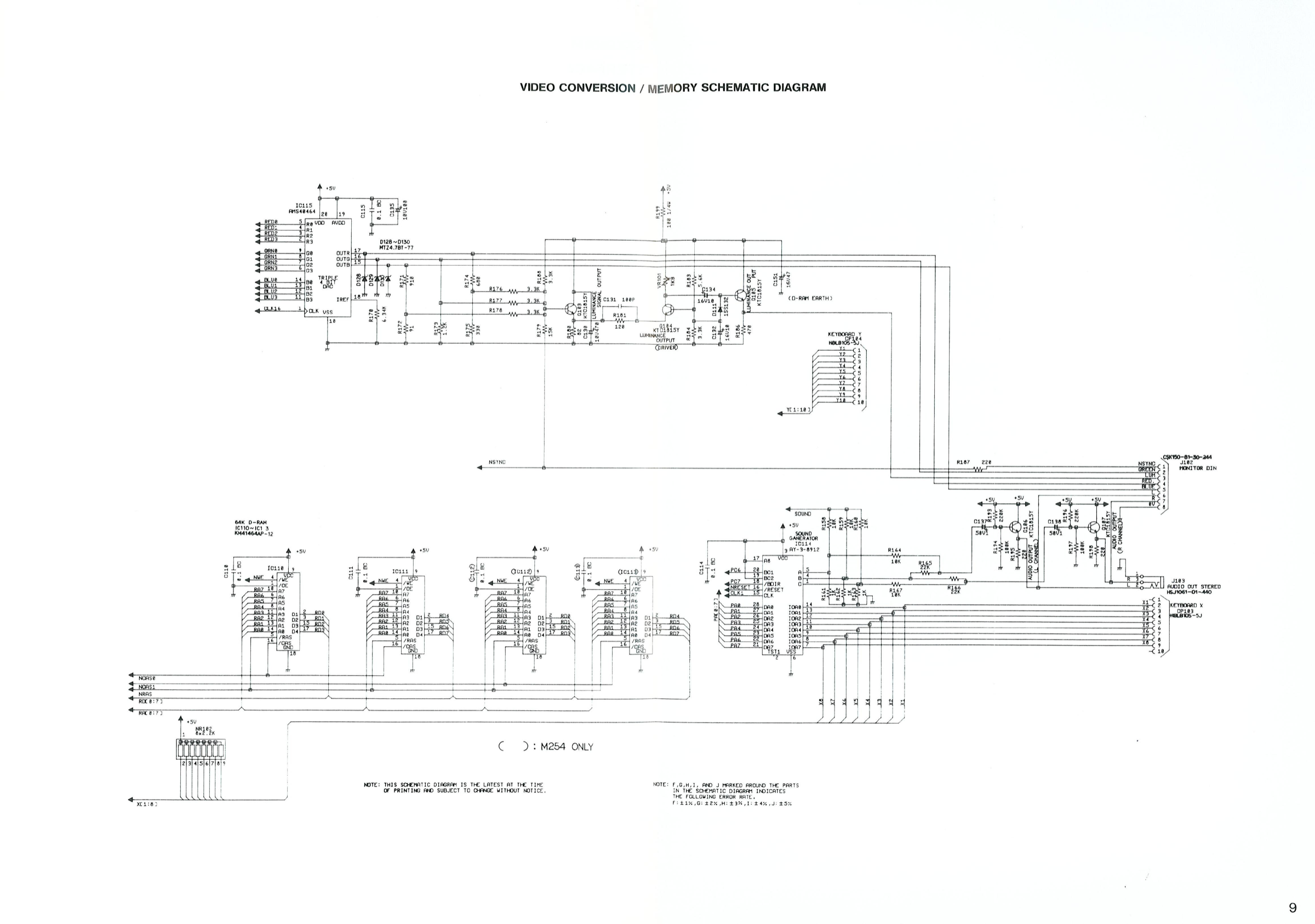
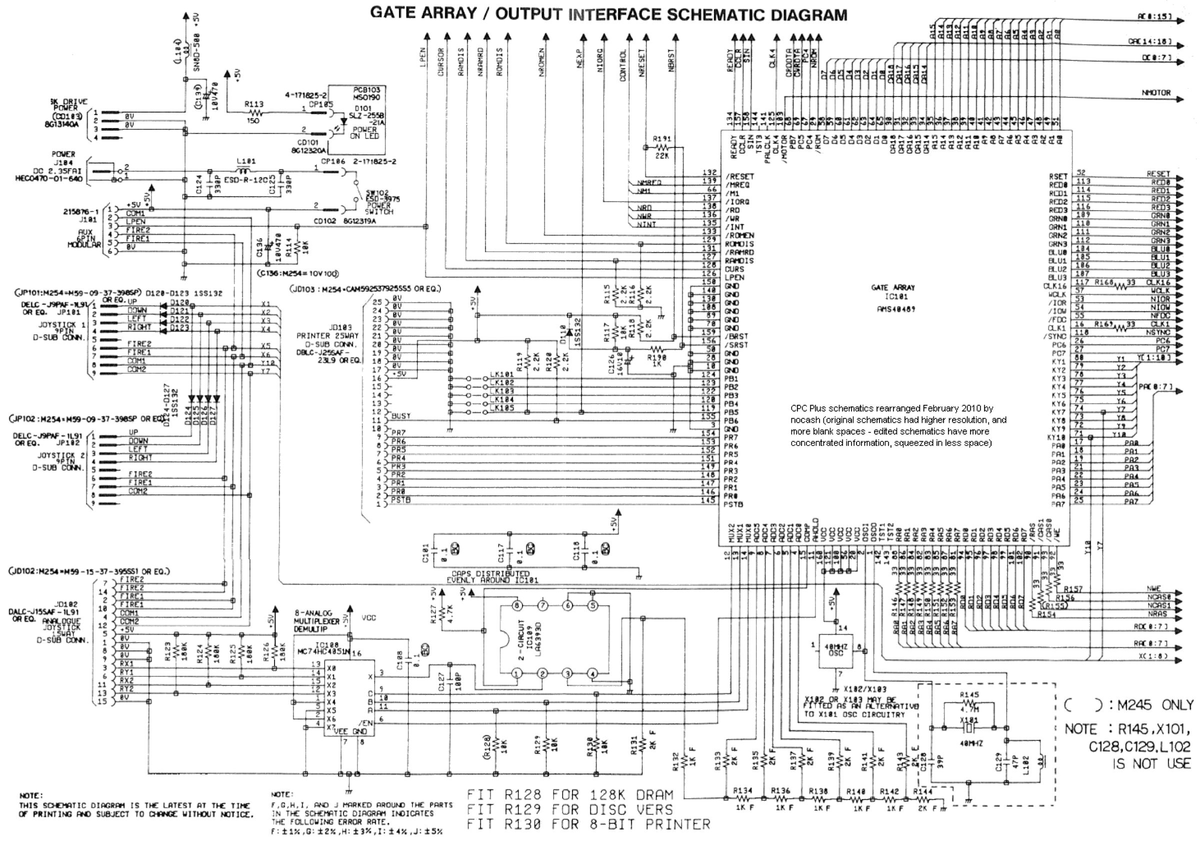
Manufacturer documentation archived locally: schematics, block diagrams, expected voltages, parts lists. The reference when a symptom matches no known fault.
- 6128 Plus — PDF
Status
Manufacturer documents kept for preservation (machines out of production for decades), with no explicit licence — the same position as for the cabinet manuals already archived here.
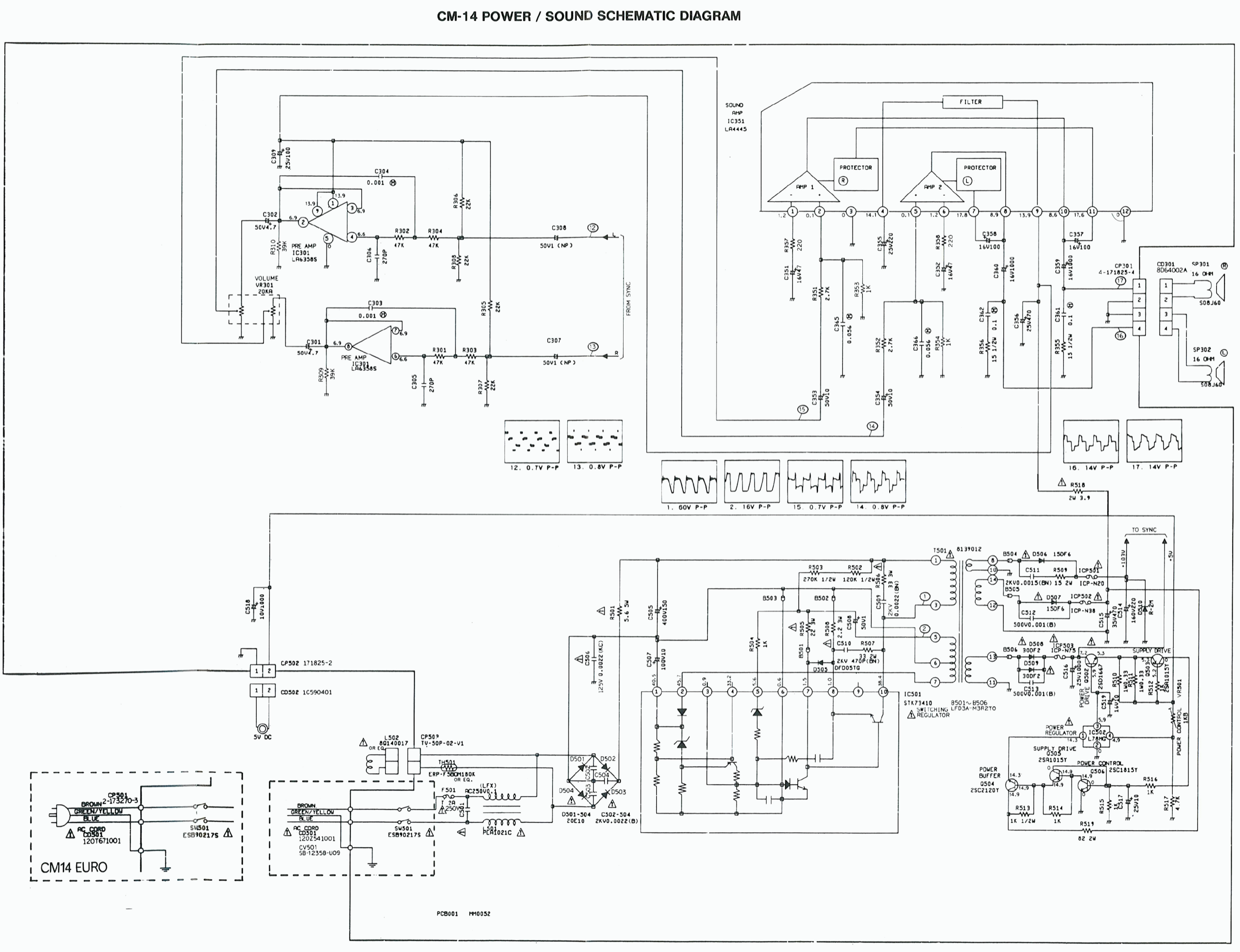
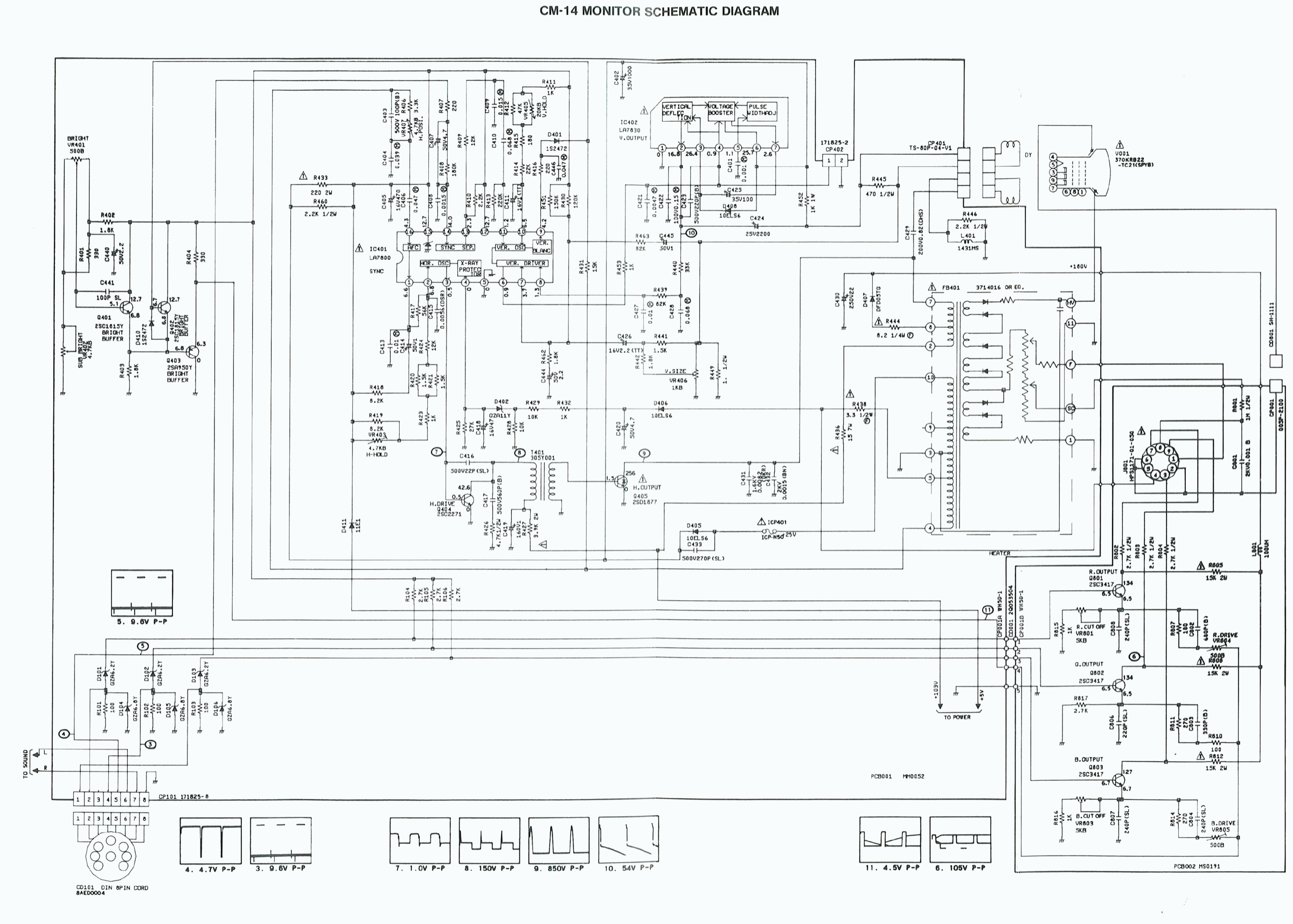
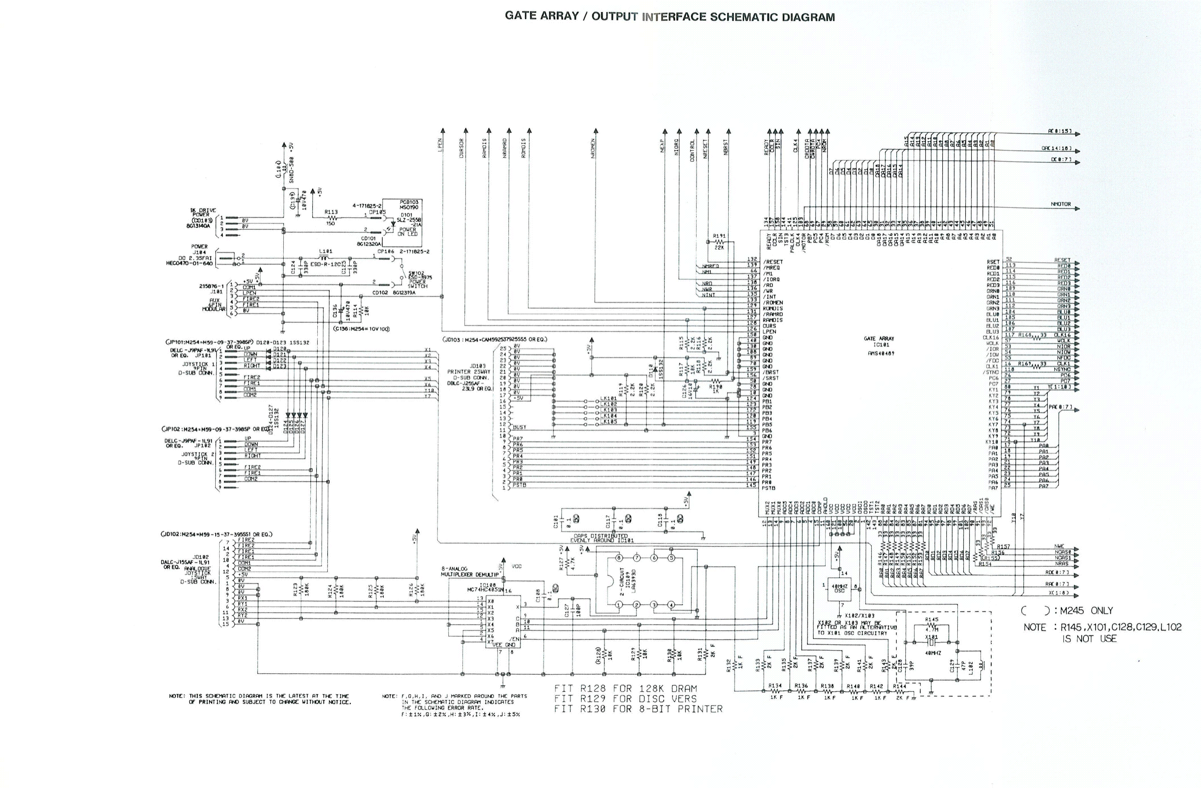
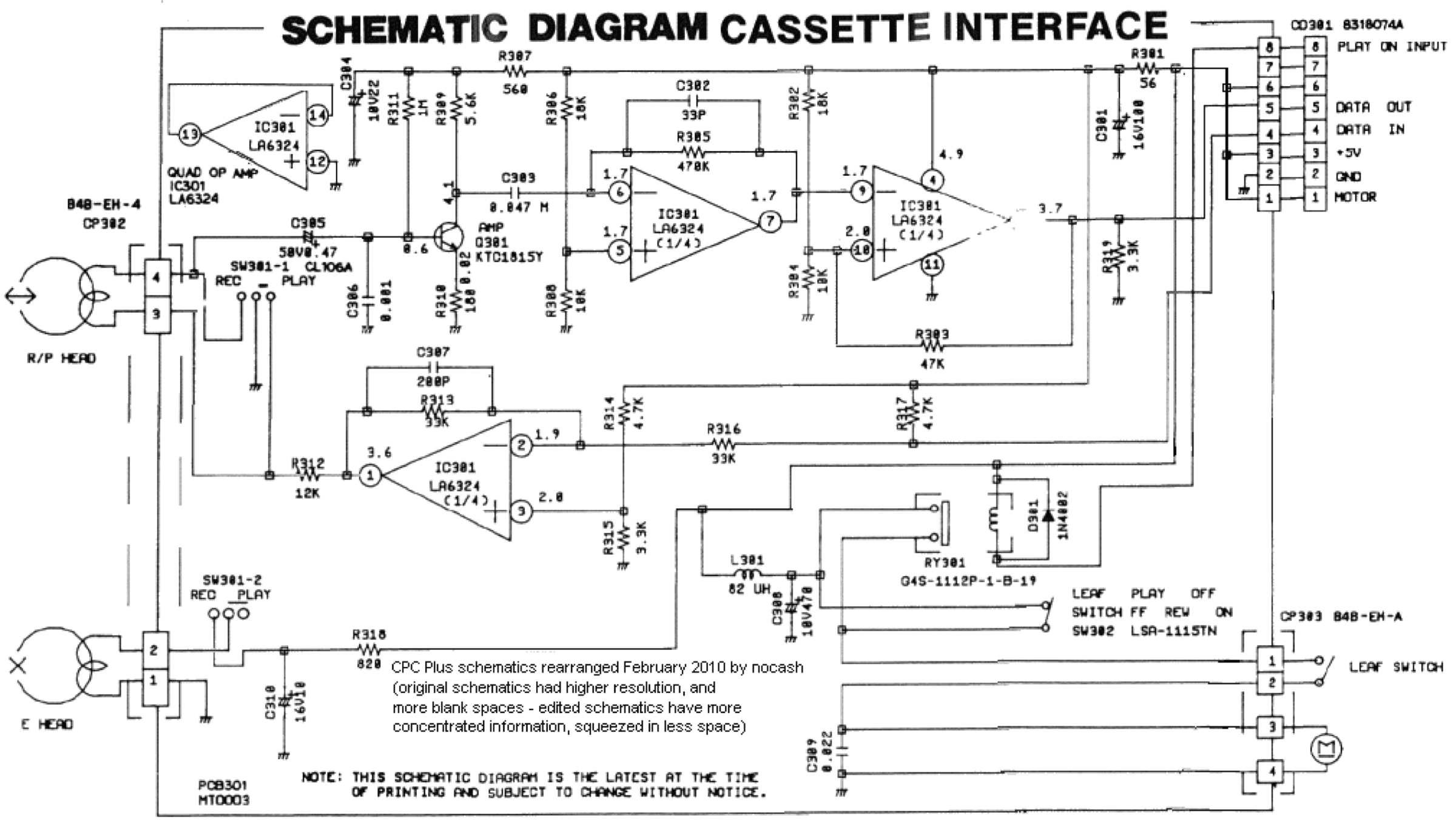
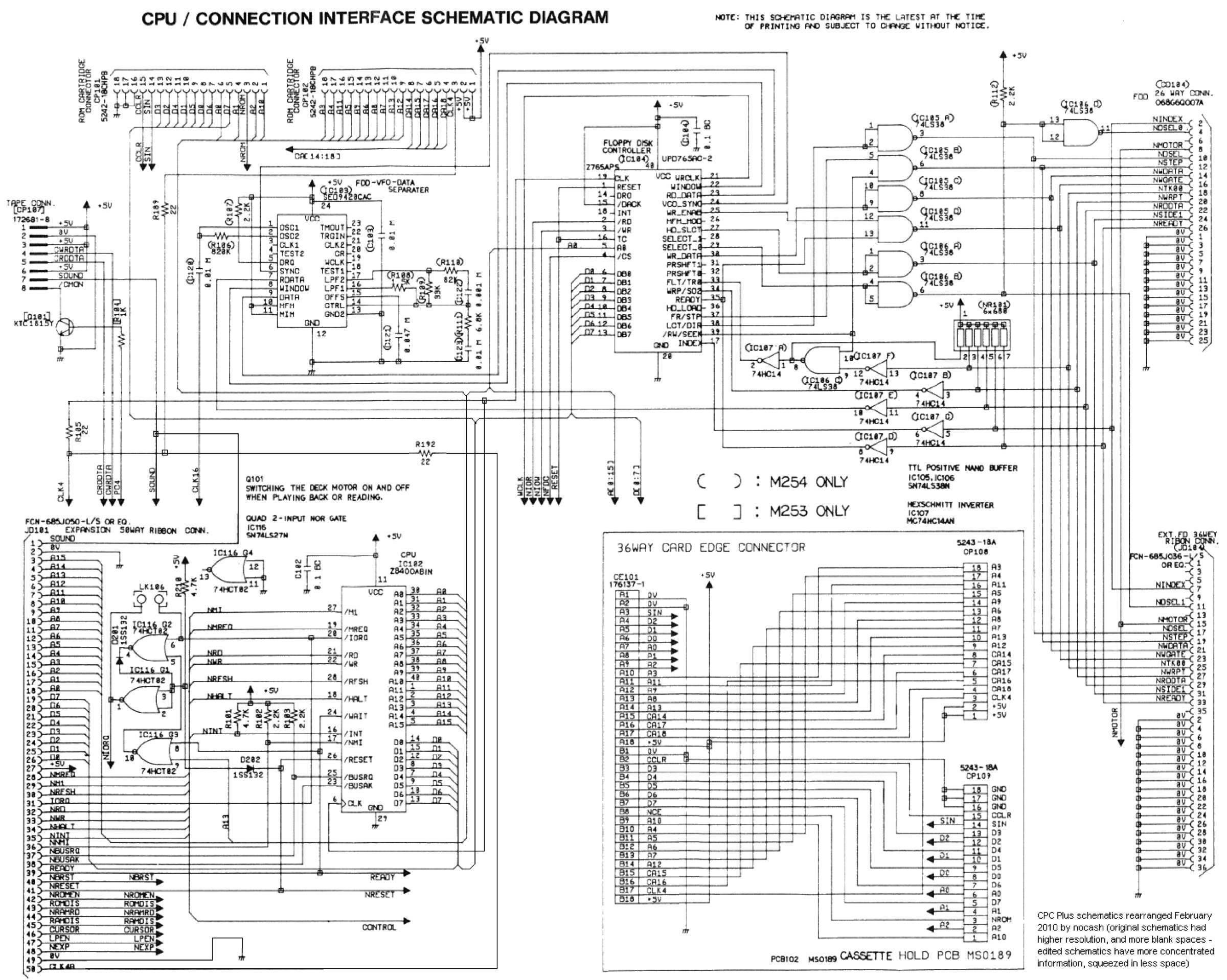
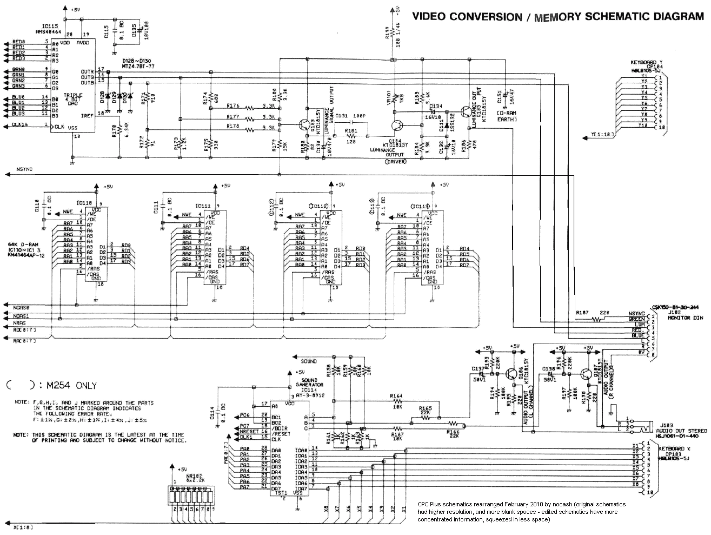
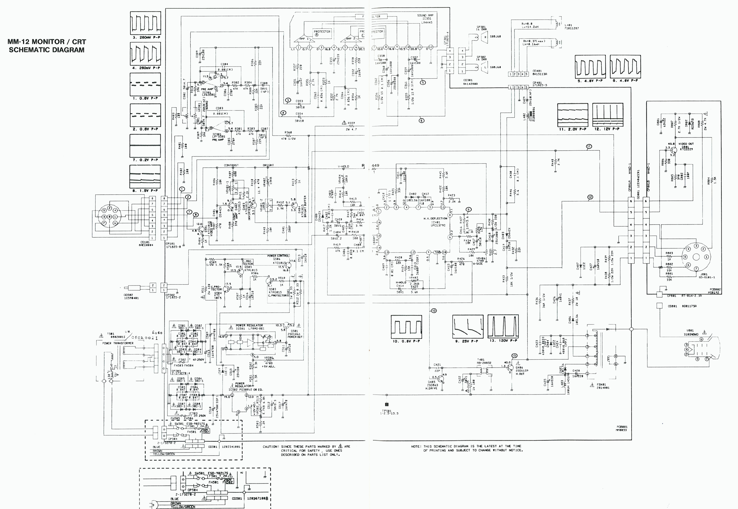
CPC Plus schematics ✅
ASIC, CPU, video memory, cassette, plus the CM14 and MM12 monitors.
Provenance
Schematics of undocumented origin in the collection they came from: no author and no licence is stated there.
Sources & attribution
-
Photo Amstrad 6128 Plus — Thomas Vogt, CC BY 4.0, Wikimedia Commons — https://commons.wikimedia.org/wiki/File:Amstrad_6128Plus_(54848973881).jpg
-
Wikipedia — Amstrad CPC → Plus range (ASIC, sprites, 4096 palette, DMA sound, models) — CC-BY-SA — https://en.wikipedia.org/wiki/Amstrad_CPC
- Internal: GX4000 (same hardware, on cartridge)
- CPCWiki — Plus / ASIC — to reference — https://www.cpcwiki.eu/index.php/Plus
.jpg)
Review & corrections
How this space is used
Spotted a wrong value, an outdated procedure, a chip reference that does not match your board? Say so here, with what you observed (model, board revision, serial number, measurement). Every report is cross-checked against a source before anything changes — an unverifiable correction is published as “reported by …, not cross-checked” rather than silently applied.
Reading is open to everyone; posting requires signing in with Discord. Reports from the wiki's declared reviewers are handled first; anyone else's are read too, but go through a human before anything is changed.