JVS I/O boards (models & wiring)
The JVS I/O board is the go-between for the control panel (buttons, joysticks, wheels, coin mechs, lamps) and the game/PC connected over JVS. This is where a modern cabinet's control panel is physically wired.
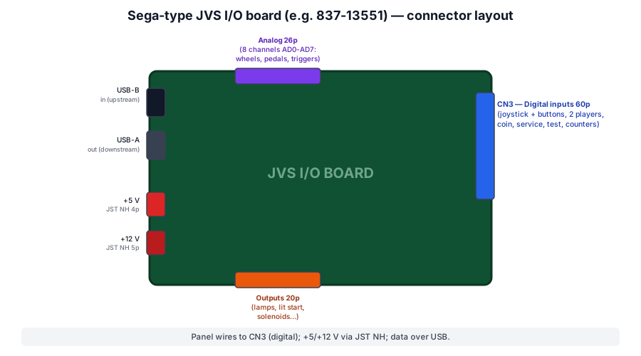
Role
The master (game or arcade PC) doesn't read the buttons: it polls the I/O board over serial. The board:
- reads digital inputs (joystick + buttons, ×2 players, coin/service/test);
- reads analog inputs (wheel, pedals, triggers — 8 channels);
- drives outputs (counters, lit start, lamps, solenoids);
- reports to the master (player / button / channel / output counts) at power-up.
Connectors (Sega 837-13551, the most common board)
| Connector | Type | Function |
|---|---|---|
| Data in | USB-B | to upstream (master or previous board) |
| Data out | USB-A | to downstream (next chained board) |
| +5 V | JST NH 4-pin | 1-2: +5 V · 3-4: GND |
| +12 V | JST NH 5-pin | 1-2: +12 V · 4-5: GND |
| CN3 — digital inputs | 60-pin JST | 2-player panel: +5 V, GND, joystick, buttons 1-7, service, test, coin, counters |
| Analog | 26-pin | 8 channels AD0-AD7 (+ Vcc/GND) |
| Outputs | 20-pin | outputs 1-6 (or more): lamps, lit start… |
Wiring the panel (CN3, 60-pin)
The control panel connects to CN3. Typical map: pins 1-8 = +5 V, 9-16 = GND, 17-44 = player 1 & 2 controls (joystick + buttons 1-7, service, test, coin, counter), 51-56 = outputs, 57-60 = +12 V. Inputs are active-low (contact to GND), just like JAMMA. Check the board's silkscreen: exact numbering varies between models.
Pin-by-pin: Sega 837-13551-92 (60-pin)
Here is the complete, pin-by-pin pinout of the 60-pin (AMP) panel connector on the Sega 837-13551-92 ("Type 1", the most common on Naomi / JVS candy cabs). All control inputs are active-low (contact to GND).
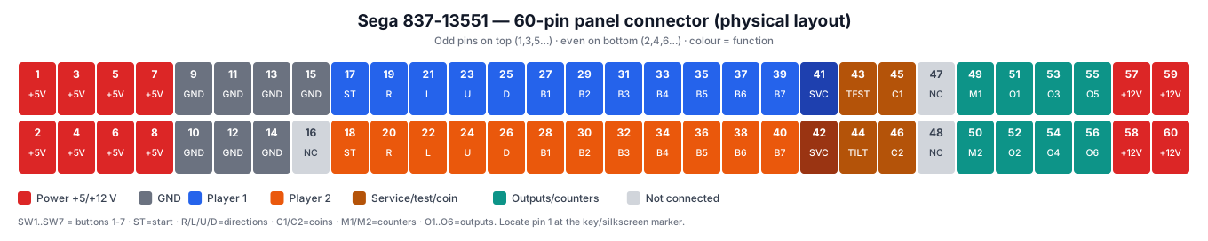
Power & ground (1-16)
| Pin | Signal | Pin | Signal | |
|---|---|---|---|---|
| 1-8 | +5 V (panel power) | 9-15 | GND | |
| 16 | N.C. |
Start & directions (17-26) — (1P then 2P alternating)
| Pin | Signal | Pin | Signal | |
|---|---|---|---|---|
| 17 | 1P Start | 18 | 2P Start | |
| 19 | 1P Right | 20 | 2P Right | |
| 21 | 1P Left | 22 | 2P Left | |
| 23 | 1P Up | 24 | 2P Up | |
| 25 | 1P Down | 26 | 2P Down |
Buttons SW1-SW7 (27-40)
| Pin | Signal | Pin | Signal | |
|---|---|---|---|---|
| 27 | 1P Button 1 | 28 | 2P Button 1 | |
| 29 | 1P Button 2 | 30 | 2P Button 2 | |
| 31 | 1P Button 3 | 32 | 2P Button 3 | |
| 33 | 1P Button 4 | 34 | 2P Button 4 | |
| 35 | 1P Button 5 | 36 | 2P Button 5 | |
| 37 | 1P Button 6 | 38 | 2P Button 6 | |
| 39 | 1P Button 7 | 40 | 2P Button 7 |
Service / test / coins (41-46)
| Pin | Signal | Pin | Signal | |
|---|---|---|---|---|
| 41 | 1P Service | 42 | 2P Service | |
| 43 | Test | 44 | Tilt | |
| 45 | Coin 1 (Coin SW1) | 46 | Coin 2 (Coin SW2) |
Outputs & counters (47-56)
| Pin | Signal | Pin | Signal | |
|---|---|---|---|---|
| 47-48 | N.C. | 49 | Coin counter 1 | |
| 50 | Coin counter 2 | 51-56 | Outputs 1 to 6 |
Power +12 V (57-60)
| Pin | Signal |
|---|---|
| 57-60 | +12 V (power outputs: lit start, lamps) |
Verify on the actual board
-
Pin 16 is listed N.C. by the harness database; some references fold it into the GND (9-16) range. When in doubt, follow the board's silkscreen.
-
Dual-row AMP connector: the odd pins (1,3,5…) sit on one row, the even ones (2,4,6…) on the other, by columns (see the visual). Locate pin 1 at the key / silkscreen marker before wiring.
-
The panel connector's +5 V and GND must be present for the inputs to be read.
Pinout: Sega 838-13683 (JVS ↔ JAMMA)
The 838-13683 (rev. -93 / -02) is a special case: instead of a panel connector it exposes a JAMMA edge. You plug the game's JVS (Naomi…) on one side, and on the other you get a standard JAMMA harness — ideal to reuse a candy cab's JAMMA wiring. It's the go-to board for dropping a Naomi into an Astro/Blast City without rewiring the panel.
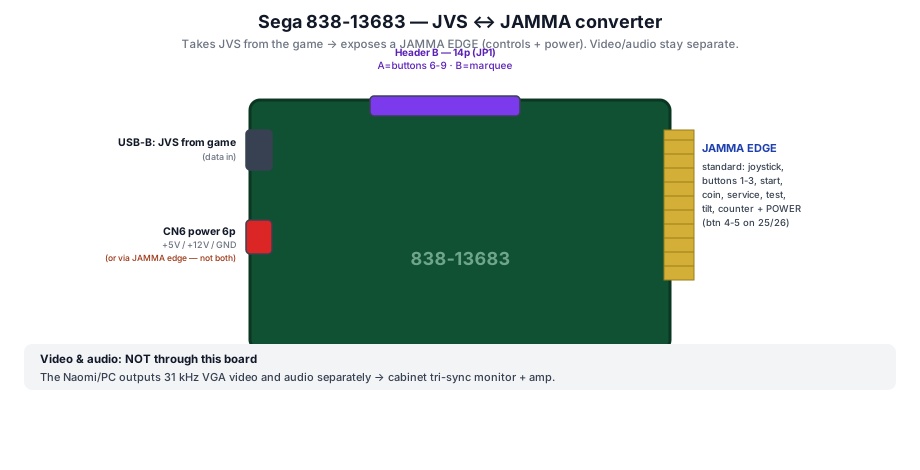
The JAMMA edge carries NO video or audio
It's an I/O board: the JAMMA edge carries controls + power only. The Naomi/PC outputs 31 kHz VGA video and audio separately → cabinet tri-sync monitor + amp. A 15 kHz-only candy monitor will not display the Naomi.
The JAMMA edge
It follows the standard JAMMA pinout for the base controls: joystick, buttons 1-3, start, coin, service, test, tilt, counter, + power +5/+12/−5 V and GND. Buttons 4-5 come out on pins 25/26 (de-facto extension, see the JAMMA page). Buttons 6-9 run through the Header B below.
Power — CN6 (6-pin)
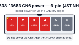
| Pin | Signal |
|---|---|
| 1-2 | +5 V |
| 3-4 | +12 V |
| 5-6 | GND |
Only one power source at a time
Power either through the JAMMA edge or through CN6 — never both at once (conflict / back-feed risk).
Header B — extra buttons / marquee (14-pin)
A 14-pin connector whose role depends on the JP1 jumper: A = input (extra buttons), B = output (digital marquee/billboard, e.g. VS City).
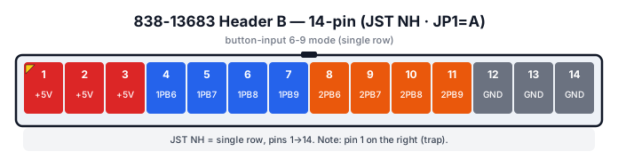
| Pin | JP1 = A (button input) | JP1 = B (marquee output) |
|---|---|---|
| 1-3 | +5 V | +5 V |
| 4 | 1P Button 6 | Billboard Out 0 |
| 5 | 1P Button 7 | Billboard Out 1 |
| 6 | 1P Button 8 | Billboard Out 2 |
| 7 | 1P Button 9 | Billboard Out 3 |
| 8 | 2P Button 6 | Billboard Out 4 |
| 9 | 2P Button 7 | Billboard Out 5 |
| 10 | 2P Button 8 | Billboard Out 6 |
| 11 | 2P Button 9 | Billboard Out 7 |
| 12-14 | GND | GND |
Button numbering & connector orientation
-
Depending on the source, these buttons are labelled 6-9 (the JAMMA edge already providing 1-5) or 4-7 (if the edge only uses 1-3). The physical pin order is the same; only the label changes with the game/mode.
-
Orientation trap: the connector can be plugged in backwards — numbering starts from the right (pin 1), not the left. Check the key.
-
Via a CPS2 kick-harness adapter, this Header B feeds buttons 4/5/6 for both players on a "CPS2"-wired candy cab.
-
On some revisions a JP2 also switches Header B's role (input / 8 general outputs). Check the silkscreen.
Every JVS I/O board (per-model detail)
A complete rundown of the boards you'll meet, with connectors and pinout where publicly documented. The two Sega boards 837-13551 (Type 1) and 838-13683 (JVS↔JAMMA) are detailed pin-by-pin above.
Common Sega connectors (analog & outputs)
Several Sega boards (Type 2 / Lindbergh…) share these two connectors, on top of the 60-pin panel and JST NH power.
26-pin analog connector (wheels, pedals, triggers — 8 channels AD0-AD7)
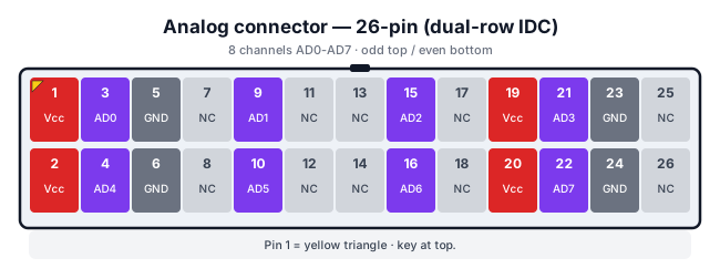
| Pin | Signal | Pin | Signal |
|---|---|---|---|
| 1-2 | Vcc | 19-20 | Vcc |
| 3 | AD0 | 4 | AD4 |
| 9 | AD1 | 10 | AD5 |
| 15 | AD2 | 16 | AD6 |
| 21 | AD3 | 22 | AD7 |
| 5-6, 23-24 | GND | others | N.C. |
20-pin output connector (outputs 7 to 20: lamps, feedback)
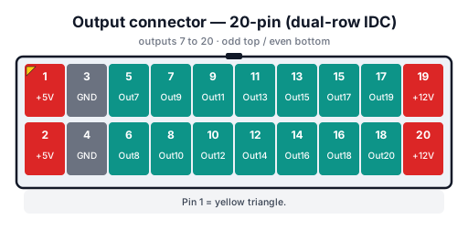
| Pin | Signal | Pin | Signal |
|---|---|---|---|
| 1-2 | +5 V | 3-4 | GND |
| 5-6 | Out 7 / Out 8 | 7-8 | Out 9 / Out 10 |
| 9-10 | Out 11 / 12 | 11-12 | Out 13 / 14 |
| 13-14 | Out 15 / 16 | 15-16 | Out 17 / 18 |
| 17-18 | Out 19 / 20 | 19-20 | +12 V |
(Outputs 1-6 are on the 60-pin panel connector; 7-20 on this 20-pin connector.)
Sega 837-14572 ("Type 2 / 3", Lindbergh)
Sega's latest revision: compatible with Lindbergh, RingWide, RingEdge, and also
Naomi / Triforce / Chihiro. Identifies as SEGA CORPORATION;I/O BD JVS;837-14572;Ver1.00.
- JVS 2.0, 2 players up to 14 buttons/player (8 usable), 2 coin slots.
- 8 analog channels at 10-bit resolution (vs 8-bit on Type 1).
- 20 outputs (vs 6): outputs 1-6 on the 60-pin, 7-20 on the 20-pin connector above.
- Panel: same 60-pin connector as the 837-13551.
- Power: CN1/CN2 (+12 V, JST NH 5-pin), CN7/CN8 (+5 V, JST NH 4-pin).
- Close variants: 837-14505 ("Type 3"), 837-15257 (Lindbergh-like pinout, USB port).
Sega 837-13844 ("I/O Control BD 2", F355 Challenge)
ⓘ Part number taken from the parts list of the F355 Challenge manual, under the label "I/O CONTROL BD 2 FOR JVS FRI". ⚠️ This wiki does not have this board's pinout — it is listed so the part number can be identified, not described.
ⓘ The same parts list places two solid-state relay boards beside it — 839-1148 (4A DC SSR BD NH4P) and 839-1011 (SSR 1EA BD) — which switch the cabinet's power, not its inputs.
Sega 837-13938 (rotary encoders — trackball / spinner)
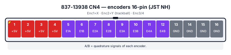
A special board for free-spinning inputs (trackball, roller, spinner). Full pinout documented:
| Connector | Type | Pinout |
|---|---|---|
| CN1 — digital I/O | 24-pin JST NH | 1-4 +5 V · 5 1P Start · 6 Service · 7-10 1P Up/Down/Left/Right · 11-12 1P SW1/SW2 · 13-20 Outputs 0-7 · 21-24 GND |
| CN2 — power | 4-pin JST NH | 1-2 +5 V · 3-4 GND |
| CN3 — JVS | USB-B | JVS data |
| CN4 — encoders | 16-pin JST NH | 1-4 +5 V · 5-6 Enc.1 A/B (X) · 7-8 Enc.2 A/B (Y) · 9-12 Enc.3/4 A/B · 13-16 GND |

Sega 838-13683 (JVS ↔ JAMMA)
Detailed pin-by-pin above (see the section): JAMMA edge + 14-pin Header B + CN6 power.
Capcom — Naomi I/O 98701 (v1.0 / v2.0)
A JAMMA-edge board (base controls) + CN3 extra buttons (enabled by JP1). Modes: 2 players / 6 buttons or (v2) 4 players / 4 buttons, 8 analog.
- Rev. A: only button 6 comes from the I/O, the rest from the JAMMA harness; Rev. B: the "kicks" come from the I/O like a standard Capcom kick harness.
- The CPS-2 / CPS-3 kick harness pinout is identical to the 4-player Capcom I/O → reusable.
- For the 3rd/4th player, pins 31/32 supply ~12 V.
- TEST → JVS TEST → INPUT TEST menu to check wiring.
Namco — Cyber Lead / NA-JV / NAJV2
The I/O of Namco candy cabs (Cyberlead, Noir). The NAJV2 identifies as
NAJV2;Ver1.00;JPN,Multipurpose. Connectors (AMP/TE family):
| Connector | Type | Role |
|---|---|---|
| J33 / J35 | AMP EI 12-pin | 1-player panel each: 1-4 joystick U/D/L/R · 5 Start · 6-11 buttons 1-6 · 12 GND |
| J38 | AMP EI 6-pin | 1 GND · 2-3 Coin 1/2 · 4-5 counters · 6 Service |
| J31 | AMP EI 2-pin | +5 V available |
| Main power | Mate-N-Lok 15-pin | +5 / +12 / +3.3 V rails + grounds |
| To LED panel | 6-pin mini-DIN | serial link to the marquee/LED board (TX/RX swapped) |
Taito — JVS-AMP, Vewlix JVS PCB, Fast I/O
| Board | Marking | Details |
|---|---|---|
| JVS-AMP Ver2.00 | K91X1025F | Type X2 kits, Egret 3 / Atomiswave SD cabinets; built-in stereo amp (volume via a cabinet pot); JVS 3.0, 2 players 15+9 buttons, 7-bit analog; 14-pin Header B (JP2: buttons 6-9 or 8 outputs) |
| Vewlix JVS PCB Ver2.00 | — | Vewlix cabinets; TAITO 60-pin panel connector (key and pinout differ from Sega — not interchangeable); 2 players 5 buttons (11 inputs/player), 8 outputs |
| Fast I/O | K91X1204/1243 | Taito's own Ethernet link (not USB) |
Taito specifics — don't confuse with Sega
- Taito I/O boards only accept +12 V as power input (no separate +5 V like Sega).
- The Taito 60-pin panel connector ≠ Sega: same apparent format, but different key and pinout → never cross a Sega harness with a Taito board. Hence the existence of Vewlix ↔ Sega I/O adapters.
Others
| Maker | Board | Profile |
|---|---|---|
| RS Co. Ltd | 081202 | generic: 2 players, 7 buttons, 2 coins, 6 outputs |
Wiring: connection order
- Data: JVS cable from game/PC (USB-A) to the I/O board (USB-B). Optional chain USB-A → USB-B to a 2nd board.
- Power: +5 V (JST NH 4-pin) and +12 V (JST NH 5-pin) from the cabinet PSU. Set +5.0 V measured at the board.
- Panel: to CN3 (60-pin). Common ground daisy-chained across the buttons (see Control panels & buttons).
- Analog: wheel/pedals on the AD connector (driving games).
- Outputs: counters, lit start, lamps on the output connector.
- End of chain: nothing to do — the SENSE line handles detection (no termination plug, unlike a true industrial RS-485 bus).
The board describes itself — and the test screen shows it ✅
✅ What really separates JVS from JAMMA
ⓘ On JAMMA, the pinout is fixed: pin 18 is pin 18, for every game. ✅ On JVS, the I/O board tells the host what it can do — players, buttons, coin slots, analog channels, outputs — and the game adapts. ⓘ That is why one cabinet runs a shooter, a driving game and a rail-shooter.
⚠️ And that report is readable: the test menu displays it field by field. Here is the fully populated screen from the Naomi GD-ROM manual, for a Sega I/O board:
NODE       1/1                 ← current board / total number of boards
NAME       XXXXXXXXXX          ← ID code returned by the board
I/O  XXX-XXXXX                 ← board part number and version
VER  XXXX
CMD VER    1.1                 ← command format version
JVS VER    2.0                 ← JVS standard version
COM VER    1.0                 ← communication version
SWITCH     2PLAYER(S) 11BITS   ← players, and switch bits per player
COIN       2SLOT               ← coin slots
ANALOG     8CH                 ← analog channels (wheel, pedals…)
ROTARY     0CH                 ← encoders (trackball, spinner)
KEYCODE    0
SCREEN     X:0 Y:0 CH:0        ← screen position (light guns)
CARD       0SLOT
HOPPER OUT 0CH
DRIVER OUT 8SLOT               ← power outputs (lamps, force feedback)
ANALOG OUT 0CH
CHARACTER  CHARA:0 LINE:0
BACKUP     0
ⓘ Three version numbers, and they are independent: CMD VER 1.1, JVS VER 2.0, COM VER 1.0. ⚠️ So "JVS 2.0" says nothing about the command format, which is 1.1 on that same board.
⚠️ The diagnostic rule this screen gives you
ⓘ This particular board declares 2 players × 11 bits, 2 coin slots, 8 analog channels and
8 outputs — and zeros everywhere else. ⚠️ A gun game needs a non-zero SCREEN; a trackball
game needs a non-zero ROTARY.
✅ Hence the rule: if the game does not see your controls, read that page first. It tells you whether the board even claims to have the input concerned.
- ⓘ Field at zero → this is not a wiring problem: the board does not have that function. You need a different I/O board.
- ⓘ Field non-zero but nothing moves → now the wiring, the connector or the sensor is at fault.
⚠️ And the screen itself depends on the board. The manual says so:
"The screen at the left is displayed when a SEGA I/O board is used. If you use an I/O board of another version, a different screen than this one is displayed."
ⓘ A screen that does not look like the manual's is therefore not a fault in itself.
ⓘ Several boards in a chain: NODE 1/1
The NODE field gives the current board and the total — 1/1 for a single one. ⓘ The
menu has a dedicated button to step to the next: "NEXT NODE: In the case where more than 2
I/O Boards are connected, proceeds to the next I/O Board."
⚠️ If a two-board cabinet shows 1/1, the second is not seen — and the problem is in the
chain, not in the controls it carries. → JVS wiring
Troubleshooting
- Nothing responds: check +5 V on the board, the JVS cable (USB-B at the board), and that the game sees the board (JVS test menu: identity, input count).
- A player / buttons missing: wrong config jumper (JP1) (button count) or CN3 wiring.
- Erratic analog: analog ground, wheel/pedal potentiometer.
- Dead lamp output: output driver (transistor) or +12 V wiring.
→ Bus & protocol: JVS wiring · Panel & buttons: Control panels & buttons.
→ Repair: PCB fault-finding · Traces & vias.
Sources & attribution
- Arcade Otaku Wiki — JVS: I/O board list (Sega 837-13551/13938/14572, 838-13683; Capcom; Namco; Taito) — https://wiki.arcadeotaku.com/w/JVS
- NFG Games / GameSX — JVS board connectors (CN3 60-pin, analog 26-pin, outputs 20-pin, JST NH power) — https://gamesx.com/wiki/doku.php?id=arcade:jvs_board_connectors
- Harness database (jammaharness) — Sega JVS I/O 837-13551-92: pin-by-pin 60-pin pinout — http://jammaharness.blogspot.com/2012/09/jvs-io-837-13551-92.html
- Arcade Otaku / Arcade-Projects — cross-check of the 837-13551 pinout (start, directions, SW1-7, service/test/coin, outputs, +12 V)
- NFG Games / GameSX — 838-13683: 14-pin Header B (JP1 A/B, buttons/marquee), JAMMA edge role — https://gamesx.com/wiki/doku.php?id=arcade:jvs_board_connectors
- Arcade-Projects — Sega JVS→JAMMA 838-13683-93, 6-button Blast City: kick harness (P1/P2 btn 6-9, GND), CN6 power, "not JAMMA + CN6 together" — https://www.arcade-projects.com/threads/sega-jvs-to-jamma-i-o-838-13683-93-6-button-with-blast-city.6438/
- Arcade Otaku Wiki — JVS: 837-14572 (Lindbergh, 10-bit, 20 outputs), Namco NAJV2, Taito JVS-AMP/Vewlix/Fast I/O, RS 081202 — https://wiki.arcadeotaku.com/w/JVS
- NFG Games / GameSX — 26-pin analog & 20-pin output connectors; Namco Cyber Lead pinouts (J33/J35, J38, power) — https://gamesx.com/wiki/doku.php?id=arcade:namco_cyber_lead_pinouts
- Arcade-Projects — Sega 837-13938 rotary encoder pinout (CN1/CN2/CN4) — https://www.arcade-projects.com/threads/sega-jvs-rotary-encoder-trackball-i-o-board-837-13938-pinout.1383/
- Focus Attack / Arcade-Projects — Capcom 98701 I/O (rev A/B, CPS-2/3 kick, 3P/4P 12 V) — https://support.focusattack.com/hc/en-us/articles/360004350071
- Internal pages: JVS wiring · JAMMA wiring · Control panels
- Sega — Naomi GD-ROM, service manual (fully populated JVS test screen: NODE / CMD VER / JVS VER / COM VER) — PDF
- Sega — The House of the Dead 4, Service Manual (list of the JVS screen fields) — PDF
- Sega — F355 Challenge, Owner's Manual (part number 837-13844, SSR 839-1148 / 839-1011) — PDF
Review & corrections
How this space is used
Spotted a wrong value, an outdated procedure, a chip reference that does not match your board? Say so here, with what you observed (model, board revision, serial number, measurement). Every report is cross-checked against a source before anything changes — an unverifiable correction is published as “reported by …, not cross-checked” rather than silently applied.
Reading is open to everyone; posting requires signing in with Discord. Reports from the wiki's declared reviewers are handled first; anyone else's are read too, but go through a human before anything is changed.