CRT safety & high-voltage discharge
Read this before any work on an arcade monitor or CRT. A tube stores a lethal high voltage even after being unplugged for days. This page covers discharge, hot-chassis and mechanical risks.
Lethal hazard
The anode of an arcade CRT sits at ~20-30 kV. The tube acts like a large capacitor that holds its charge when off. The chassis's primary electrolytics (often ~400 V) stay charged too. Never put your hands in a chassis without discharging, and never work alone if you are untrained.
Discharging the anode (before any work)
- Unplug from mains.
- Get a clip lead connected to the tube's ground return (the ground braid / the outer aquadag coating — not a floating chassis).
- Slide an insulated-handle screwdriver under the anode cap (the rubber suction cup) until it touches the metal clip beneath it.
- Wait for a possible "crack." Repeat — the charge can rebuild (dielectric effect). Some leave the discharge lead in place during work.
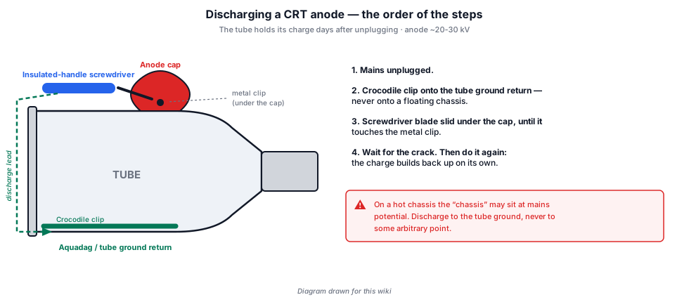
Discharge to the RIGHT point
Discharge to the tube ground, not a random point: on a hot-chassis the "chassis" may be at mains potential. Use the HV ground return.
✅ The one number the procedure above was missing: two minutes
The page already said to repeat the discharge, because the charge builds back. It did not say how long to wait. The Matsushita 19″ manual (Atari TM-220) gives it:
"When discharging the anode, go from ground to the anode connection with a well-insulated 20-kV jumper. Allow two minutes to pass and discharge the anode again."
✅ Two minutes, then again. And the tool is named: a jumper insulated for 20 kV, not whatever screwdriver is to hand.
ⓘ This is not a Matsushita instruction: it is an Atari one. The manual of the 13″ colour Amplifone (Atari TM-222), a vector monitor from an entirely different maker, gives the same sentence:
"When discharging the anode, use a well-insulated 18-guage jumper wire. Allow two minutes to pass and discharge the anode again."
⚠️ But the two manuals do not name the same tool. TM-220 specifies a voltage rating (20 kV); TM-222 specifies a conductor size (18 AWG). ⓘ Those are two different properties of the same wire, and neither is sufficient alone: 18 AWG says nothing about its insulation, "20 kV" says nothing about its gauge. ⓘ ("18-guage" is the manual's spelling.)
ⓘ And TM-222 adds the destination that TM-220 leaves implicit: "discharge the high voltage on the anode connection to ground — not to the cabinet or other mounting parts" — the same reservation as the rest of this page.
⚠️ One manufacturer advises against the \"crack\" — and this wiki holds no document that settles it
The method described above works by arc: the screwdriver approaches, the charge jumps, you hear the crack. It is the one the Motorola and Wells-Gardner manuals describe, and it protects the operator.
⚠️ But the Electrohome G05 writes the opposite — in the same paragraph as its high-voltage warning:
"In order to prevent damage to solid state devices, do not arc pix tube anode lead to chassis or earth ground."
Both are right about different things. The arc is safe for the person and brutal for the electronics: discharging a tube in a few microseconds sends a pulse through everything tied to that ground. Electrohome is protecting its semiconductors; Motorola and Wells-Gardner are protecting the technician.
⚠️ This wiki holds no manufacturer's document describing a method that satisfies both, and it does not invent one. What is stated here is what each one writes:
- the person's safety comes first — an undischarged tube can kill you, a blown transistor cannot. The procedure above remains this page's procedure;
- ⚠️ but if the chassis matters to you as much as your hands, know that at least one manufacturer treats a hard arc as a cause of damage, and say so before blaming the original fault;
- ✅ and on one point all three agree: never the cabinet, never a mounting part.
✅ That question was open. It is no longer — see the box that follows.
✅ The answer has arrived: 10 kΩ in series, between dag and anode
The Wells-Gardner 19V2000 manual prescribes exactly the method that was missing:
"When servicing the High Voltage System, remove static charge from it by connecting a 10K Ohm resistor in series with an insulated wire (such as a test probe) between picture tube dag and 2nd anode lead. (Input plug disconnected from chassis)."
✅ It satisfies both constraints this wiki could not reconcile:
- the 10 kΩ series resistor removes the hard arc — precisely what the Electrohome G05 asked for when it forbade "do not arc pix tube anode lead to chassis or earth ground" to protect the semiconductors;
- and the path runs from the tube's dag to the anode, not to the chassis — the point this page has prescribed all along, stricter than the "chassis ground" of Motorola and of Wells-Gardner itself elsewhere.
⚠️ Input plug disconnected from the chassis, the manual specifies.
ⓘ What this changes in the procedure at the top of the page: the screwdriver gesture stays described because it is widespread and it protects the operator, but the method documented by a manufacturer is this one. ⚠️ It calls for an accessory — a 10 kΩ resistor in series on an insulated wire — that must be made up before opening the cabinet, not at the moment it is needed.
ⓘ And the same manual gives the direction of the measurement: to check for the presence of high voltage, a high-impedance EHT meter, connected "between second anode lead and metal chassis frame only".
The direction of the gesture: two manufacturers say it word for word
The Motorola VP12 and Wells-Gardner Quadrascan colour manuals — two different firms, two decades apart, one raster and one vector — write the same sentence:
"When discharging, go from ground to anode, or use a well-insulated piece of wire."
✅ That is the order described above, and it is not cosmetic: the clip is placed and held on ground first, and only then does the other end approach the anode. Done the other way round, you are holding a conductor already at 25 kV while looking for somewhere to clip it.
⚠️ Where this wiki stays stricter than both manuals. They write "short the anode connection to chassis ground — not the cabinet or other mounting parts". This wiki prescribes the tube's ground return (the aquadag), not the chassis:
- on chassis where the tube's return is bonded to the chassis, the two instructions name the same point and there is no disagreement;
- ⚠️ but on a hot chassis, the chassis is at mains potential — and the table below shows you cannot tell which you have without the manual. The wiki's instruction is right in both cases; the manuals' is right only in theirs.
✅ On one point, though, all three agree without reservation: never the cabinet, never a mounting part.
Hot-chassis & isolation transformer
- Many arcade chassis are "hot": the circuit ground is tied to mains (no galvanic isolation). Touching ground and earth = shock.
- Always put an isolation transformer between mains and the monitor/cabinet when working on it powered. It breaks the earth reference and makes a hand-to-earth path non-lethal (but stay careful).
- Measurement: a scope on a hot-chassis without isolation can short through the probe ground → isolation mandatory.
\"Hot\" or not: you cannot tell by looking, and the makers themselves disagree
This wiki holds six monitor manufacturers' manuals, and they do not say the same thing — because they describe different designs. ⚠️ Two of them use exactly the same phrase — "the chassis and the heat sink(s)" — to state the opposite of each other:
| Chassis | What the maker writes |
|---|---|
| Hantarex MTC9000 | service at 128 V through an isolating transformer, not on the mains |
| Electrohome G07 | "an isolation transformer must be used for the AC power source" |
| Wells-Gardner 19″ In Line | "an isolation transformer must be used […] since the chassis and the heat sink are directly connected to one side of the AC line" |
| Hantarex MTC 9110 | ⚠️ "The chassis and the heat sinks are connected to earth. […] connect the negative terminals of instruments to the chassis" — the same two words as Wells-Gardner, the opposite conclusion |
| Motorola 19VP111 / 23VP111 | "An isolation transformer should always be used during the servicing of a unit whose chassis is connected to one side of the power line" — the only one to state the condition rather than the instruction |
| Sejoo/Eurocoin "Vision" KTM-F | "The power supply of this chassis design provides isolation, so a separate isolation transformer is not required for normal operation." |
⚠️ None of that is readable off the chassis. An isolated switch-mode supply and a mains-referenced chassis look alike, and the rule above — always use the isolation transformer — stays the right one precisely because you cannot know without the document. Being wrong one way costs you a transformer you did not need; being wrong the other way costs something else.
⚠️ And even the maker who writes "not required" does not write "safe": it writes "for normal operation", and on the same page "High Voltage must be completely discharged before handling". None of these three sources excuses you from discharging the tube.
The isolation transformer comes off for one measurement — and one only
⚠️ There is one check that requires removing it, and it is the one that decides whether the cabinet is safe for its player. Motorola writes it in capitals: "BEFORE RETURNING A SERVICED UNIT […] DO NOT USE A LINE ISOLATION TRANSFORMER WHEN MAKING THIS TEST."
The reason is mechanical: the transformer breaks the earth reference, and that reference is exactly what the test measures. On a transformer, a dangerous cabinet passes.
The leakage test, with its acceptance value — ⓘ one of two numeric criteria on this wiki; the Electrohome G02 gives another, and the two do not agree (see below):
- a 1000 Ω/V AC voltmeter, shunted with a 1500 Ω 10 W resistor;
- one probe on any part reachable by the player — trim, hardware, controls, knobs; the other on a true earth (cold water pipe kind);
- ⚠️ the reading may not exceed 7½ V AC. Above that, there is "a potentially dangerous leakage path";
- repeat with the power plug reversed, where the socket allows it;
- ⚠️ "NEVER RETURN A MONITOR which does not pass the safety test until the fault has been located and corrected."
The two instructions do not contradict each other. The transformer protects the repairer during the work; it comes off for the final check that protects the player afterwards. → Motorola VP12 manual
✅ Where the transformer actually matters — the only manufacturer that bounds it
Every manual above says whether an isolating transformer is needed. The Hantarex Polo 25″ schematic is the only one that says where:
"Whenever voltage checks are to be made in the primary circuits of the power supply […] it is necessary to isolate the monitor […]. This precaution is not necessary when making measurements in the monitor section (deflexion and video), nor in the secondary circuits of the power supply."
⚠️ This is not permission to go without — it is the scope of the protection, written by a manufacturer: it targets the supply primary. Knowing which side of the supply your probes are on is part of the job.
ⓘ And the transformer's rating, which nobody else gives: input 110-120 V AC, output 110-120 V AC, 200 W minimum. ⚠️ The Wells-Gardner 19″ and the Electrohome G07 instead speak of a 1 A minimum transformer — two ways of sizing the same thing, at opposite ends of the screen-size range.
⚠️ That same document contradicts itself between translations on the instruments' earth — four versions say disconnect it, the Spanish says connect it. The detail is on the Hantarex page, with all five quotations.
⚠️ Two manufacturers give a numeric criterion, and they do not agree
This wiki now holds two leakage tests with an acceptance value. ⚠️ The measuring network and the limit differ:
| Motorola VP12 | Electrohome G02 | |
|---|---|---|
| Voltmeter | 1000 Ω/V AC | 1000 Ω/V or better |
| Measuring network | 1500 Ω 10 W resistor shunting the voltmeter | 1500 Ω 10 W resistor paralleled by a 0.15 µF capacitor |
| Points | exposed part ↔ true earth | exposed part ↔ true earth |
| Plug reversed | yes | yes |
| ⚠️ Limit | 7.5 V AC | ⚠️ 0.3 V RMS, "this corresponds to 0.5 milliamp AC" |
⚠️ A factor of twenty-five separates the two limits, and this wiki long refused to arbitrate. ✅ A third document now allows it — and corrects a claim on this page along the way.
✅ A third maker settles it: the limit is a CURRENT, not a voltage
The Sony PVM-1341/1342Q/1343MD service manual gives the same check, and frames it differently:
"The AC leakage from any exposed metal part to earth ground and from all exposed metal parts to any exposed metal part having a return to chassis, must not exceed 0.5 mA (500 microamperes)."
ⓘ The limit is a current. Voltage is only one of three ways Sony offers to measure it: a commercial leakage tester (Simpson 229, RCA WT-540A), a battery-operated AC milliammeter (Data Precision 245), or the voltage drop across a resistor — ⓘ "the 'limit' indication is 0.75 V", on a 1.5 kΩ in parallel with 0.15 µF network.
⚠️ And this page claimed that "the 0.15 µF capacitor exists only at Electrohome". That is wrong: Sony uses exactly the same network. ⓘ The claim is withdrawn.
| Motorola VP12 | Electrohome G02 | Sony PVM-1341 | |
|---|---|---|---|
| Network | 1500 Ω shunting the voltmeter | 1500 Ω ∥ 0.15 µF | 1.5 kΩ ∥ 0.15 µF |
| Limit as written | 7.5 V | 0.3 V "corresponds to 0.5 milliamp" | ⓘ 0.5 mA, indication 0.75 V |
| ⓘ Corresponding current, computed here on the stated resistor | 5 mA | 0.2 mA | 0.5 mA |
⚠️ The calculation is this wiki's, not the makers' — it applies Ohm's law to the values each document writes. ⓘ It shows two things:
- ✅ Sony is consistent with itself: 0.5 mA × 1.5 kΩ = 0.75 V, exactly the stated indication;
- ⚠️ Electrohome is not: 0.3 V across 1500 Ω is 0.2 mA, not the "0.5 milliamp" its own manual announces. ⓘ This wiki does not correct Electrohome — it notes that its two figures do not reconcile.
✅ So what to take from it has changed in kind. The criterion shared by Electrohome and Sony is 0.5 mA; ⚠️ Motorola, at 7.5 V across 1500 Ω, sits at ten times that — and its tolerance has no equivalent at the other two. ⓘ A "leakage test" without its rig and its limit still means nothing, but we now know which quantity counts.
✅ On the point that matters, though, the two agree: ⚠️ the isolation transformer must be removed for this test — "Do not use a line isolation transformer during the test" (Electrohome), "DO NOT USE A LINE ISOLATION TRANSFORMER WHEN MAKING THIS TEST" (Motorola). Two houses, two networks, the same requirement.
✅ The case the table did not foresee: the isolation is in the CABINET
The Sanyo 14″ manual (Atari TM-157, 1980) gives the explanation the positions above were missing:
"The Sanyo monitor does not contain an isolation transformer on its chassis. It is mounted instead on the game power supply. (It may appear like a regular power transformer, but is really also an isolation transformer.)"
⚠️ One monitor can therefore be isolated in its cabinet and no longer isolated on the bench — not because the chassis changes, but because the transformer stayed in the cabinet. This is exactly the case where "it worked without a transformer in the arcade" tells you nothing about what happens once the monitor is out.
⚠️ And you cannot spot it by eye: "it may appear like a regular power transformer". ⓘ One more reason for the rule at the top of the page — always the isolation transformer, because you do not know where the isolation comes from, or whether it comes at all.
✅ A second maker, the same arrangement — and this time it is the CABINET manual that says so. Taito America's G.T.C. 100 Universal Cabinet puts its electronics in a drawer at the base of the cabinet, and the drawing of that drawer names its parts: power supply, game board, line filter, AC terminal block, fuses — and an "Isol-Transformer".
ⓘ The table at the top of this page records what MONITOR manuals say. These two cases say the same thing from the other end: ⚠️ an arcade monitor's isolation is not necessarily a property of the monitor. Taking the set out of the cabinet sometimes takes the isolation out with it — with nothing on the chassis to show for it.
⚠️ A hot chassis people keep at home: the Sony PVM
ⓘ The "hot chassis" is not an arcade curiosity. The Sony PVM-14L5/20L5 service manual states it in three languages on its title page:
"AN INSULATED TRANSFORMER SHOULD BE USED DURING ANY SERVICE […] BECAUSE OF LIVE CHASSIS. THE CHASSIS OF THIS RECEIVER IS DIRECTLY CONNECTED TO THE AC POWER LINE."
⚠️ This is the monitor many keep on a desk and open readily. ⓘ The rule at the top of this page applies unchanged — isolation transformer, and the chassis ground is not earth.
✅ And that manual goes further than any archived here: it has you confirm that the protection works, both ways — it must not trip below a threshold, it must trip above. ⓘ A protector that never trips is as defective as one that trips for nothing, and only the second gets noticed in use. → Sony PVM
Powered adjustments (rules)
- One hand in your pocket (avoids arm-to-arm current through the heart).
- Ceramic/plastic alignment tools for adjustments (coils, transformers).
- Locate G2/Screen and Focus on the flyback (pots). Brightness/sharpness — see the specific chassis page.
- Don't bridge things at random; keep your free hand away from the chassis.
Mechanical risk (implosion)
- The CRT is evacuated: a knock on the neck (fragile) or the screen can cause an implosion (flying glass). Handle with goggles, gloves, and never by the neck.
- Transport: protect the neck base (the RGB board plugs onto it).
Degauss, purity, convergence (reminder)
- Degauss: the coil erases magnetisation (colour blotches) at power-up; a persistent blotch = manual degauss.
- Purity / convergence: neck-magnet and coil adjustments — see the chassis manual (specific values, not invented here).
See also
- Nanao MS8 · Nanao MS9 · Tools (isolation transformer) · Recap (chassis)
Sources & attribution
- Synthesis of established CRT safety practice (arcade/TV); precise adjustments = chassis manual.
Diagram: decharge-anode-crt.en.svg is drawn for this wiki from the text of
this page. Nothing is shown on it that is not described above.
Review & corrections
How this space is used
Spotted a wrong value, an outdated procedure, a chip reference that does not match your board? Say so here, with what you observed (model, board revision, serial number, measurement). Every report is cross-checked against a source before anything changes — an unverifiable correction is published as “reported by …, not cross-checked” rather than silently applied.
Reading is open to everyone; posting requires signing in with Discord. Reports from the wiki's declared reviewers are handled first; anyone else's are read too, but go through a human before anything is changed.