Amstrad PCW (8256 / 8512 / 9512)
Amstrad's all-in-one word processor (1985): a Z80, a built-in monochrome monitor, a 3″ drive (then 3.5″ on 9512+), a bundled printer. Not a games machine but a huge seller; runs CP/M too. Repair: integrated CRT, PSU on the monitor board, 3″ drive.
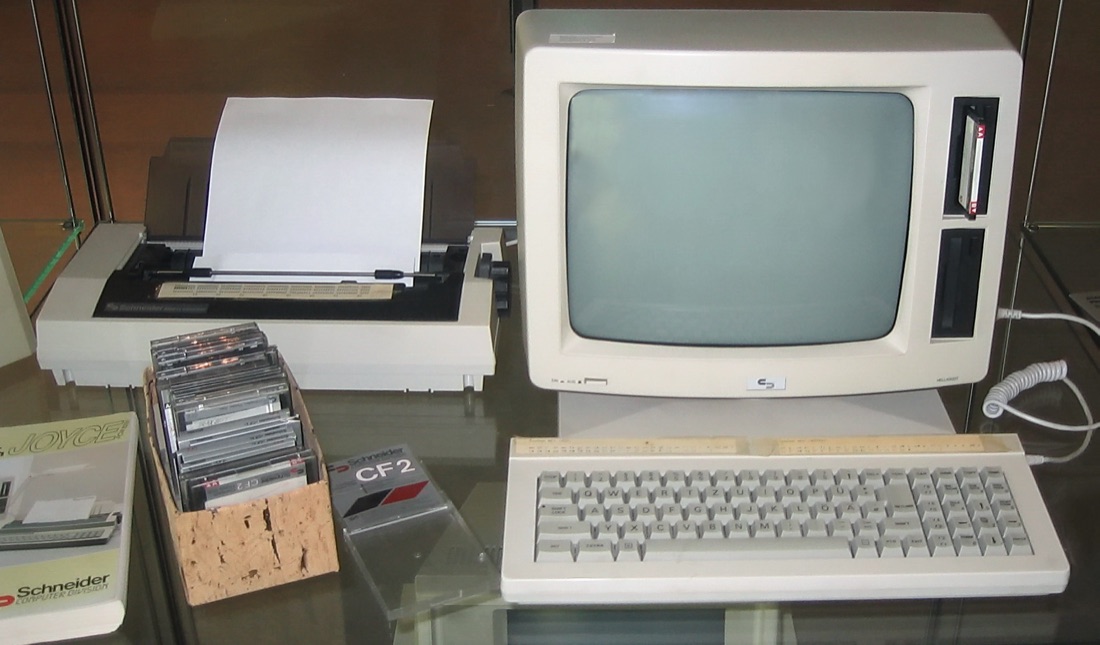
Amstrad PCW (Schneider Joyce) — photo by Johann H. Addicks, CC BY-SA 3.0 (Wikimedia Commons).
Identification
| Model | Year | Note |
|---|---|---|
| PCW 8256 / 8512 | 1985 | 256/512 KB, 3″ drive(s), dot-matrix printer |
| PCW 9512 | 1987 | daisy-wheel printer, black-on-white screen |
| PCW 9256 / 9512+ / 10 | 1991-93 | 3.5″ drives, late revisions |
Quirk: the power supply is built into the monitor; the main unit is powered through the monitor cable.
Clocks & frequencies ✅
| Component | Frequency | Role / scope |
|---|---|---|
| Z80A | 4 MHz | CPU — PCW 8256, 8512, 9512, 9256, 9512+ et PCW10 |
| Z80 | 16 MHz | CPU — PcW16 uniquement (architecture sans rien de commun avec la série d'origine) |
⚠️ Quirk: on the PCW 8256/8512/9512/9256/9512+, the Z80 has no directly connected ROM. The ASIC at the heart of the machine provides boot access instead — so a dead board is not necessarily a dead ROM.
Why this matters in repair
A clock that is missing or off-value on a frequency counter points straight at the crystal, its divider chain or the component it feeds — the fastest starting point on a machine that will not boot. Source: Wikipedia (CC-BY-SA).
Repair (technician)
CRT + PSU inside the monitor
The PCW has no external mains brick: everything comes from the monitor, which holds the CRT and the PSU. Dangerous voltages (EHT). See CRT safety and discharge before any work.
- Recap the monitor/PSU board (dried-out electrolytics → "won't power on / shuts off") → Recap.
- 3″ drive: degraded belt (the #1 cause) → replace; otherwise heads, alignment. Gotek possible.
- Monitor↔main-unit cable: tired conductors → re-check (a break = "no power to the unit").
- Keyboard: contacts / flex → clean.
Procedure — a dead computer, step by step ✅
There is a CRT inside this machine
The tube holds its charge with the machine unplugged, and on these all-in-ones the analogue board sits right where your hands go. Discharge it, or work on the logic board out of the case. → CRT safety
The power supply is in the monitor
Which means the machine will not start without it — and that a fault that looks like a dead computer may be in a part you have not even plugged in.
What this adds
Ordered for a home computer: what kills these is its power supply, its battery, its capacitors, its socketed RAM and its keyboard — roughly in that order, and well before the CPU. → PCB diagnosis
1. The power supply — measured before it is plugged in. This is the one step not to swap around. On a machine of this age a supply does not simply stop: a 5 V regulator that fails high puts 7, 9, 12 V onto the bus and takes the RAM and the custom chips with it. Measure every rail off the machine, under a dummy load if you can, and only then plug it in.
2. The battery, if it has one. Any RTC or backup cell soldered to a board is a future leak. If yours has one and it has never been changed, take it out before it takes the tracks with it. → Backup batteries
3. Capacitors. Recap is the default on these machines, not a last resort — and on the supply first, since that is what protects everything else. → Recap
4. RAM, on its sockets. These machines were built to be repaired: the RAM, and often the logic, sit in sockets. Reseat everything first — thirty years of oxide is a classic no-boot. Then swap chips: a bad RAM chip usually gives a repeatable pattern of garbage or a screen frozen at a fixed character.
5. The keyboard. A console does not have one; a computer's is a wear part. A membrane keyboard fails as whole dead rows or columns — that is the membrane, not the machine. A mechanical one wants its contacts cleaning, not replacing. Check this page: the failure mode is often documented per model.
6. Storage — tape or disk. Both often come down to the same things: a dirty head, and for tape the azimuth and a belt turned to tar. ⚠️ On the floppy side, check whether the mechanism actually has a belt before looking for one: many do, but some drives are direct drive, and hunting a belt that isn't there means stripping a drive for nothing. A machine that boots but loads nothing is a drive fault, not a logic fault — do not go looking on the board for it.
7. Video output. RF, composite, RGB or a dedicated monitor, depending on the machine (see Identification). Test with something else before you conclude: a period modulator and a modern TV disagree far more often than either is broken.
8. Still nothing. Now the logic: rails on the board, reset, clock, bus. → PCB diagnosis
Common faults
| Symptom | Likely cause | Lead |
|---|---|---|
| Won't power on / shuts off | monitor/PSU board caps | Recap |
| Floppy not read | 3″ drive belt | Replace the belt |
| Unit gets no power | monitor↔unit cable | Check conductors |
| Dead picture | CRT / PSU | CRT safety first |
Modernisation & mods — what to buy, how
Integrated screen = CRT + monitor/PSU-board recap
The PCW houses a CRT with its PSU inside the monitor block: high voltage, discharge the tube before opening → CRT safety. A recap of the monitor/PSU board cures "won't power on / shuts off"; check the monitor↔unit cable.
Modern storage
- Gotek + FlashFloppy 🟡 = the PCW flagship mod: replaces the 3″ drive (dead belts, unobtainable
CF2 disks) with a USB stick, .dsk images. Watch the ribbon keying/wiring and the original
drive density → configure FlashFloppy accordingly.
- Alternative: HxC (SD/USB) 🟡.
Video: integrated monochrome screen, no meaningful color mod.
⚠️ Do not host ROMs/software — method only.
Archived manufacturer documentation ✅
Manufacturer documentation archived locally.
Status
Manufacturer documents with no explicit licence, kept for preservation.
See also
- Amstrad CPC (same maker, same 3″) · CRT safety · Recap.
Sources & attribution
- Photo Amstrad PCW (Schneider Joyce) — Johann H. Addicks, CC BY-SA 3.0, Wikimedia Commons — https://commons.wikimedia.org/wiki/File:Amstrad_PCW_-_Schneider_Joyce.jpg
- Wikipedia — Amstrad PCW (Z80, CP/M, 3″ drive) — CC-BY-SA — https://en.wikipedia.org/wiki/Amstrad_PCW
- Established Amstrad community knowledge (3″ belt, monitor PSU) — synthesis.

Review & corrections
How this space is used
Spotted a wrong value, an outdated procedure, a chip reference that does not match your board? Say so here, with what you observed (model, board revision, serial number, measurement). Every report is cross-checked against a source before anything changes — an unverifiable correction is published as “reported by …, not cross-checked” rather than silently applied.
Reading is open to everyone; posting requires signing in with Discord. Reports from the wiki's declared reviewers are handled first; anyone else's are read too, but go through a human before anything is changed.