Atari — vector games (Asteroids, Tempest…)
A family apart: Atari's vector cabinets (late 1970s / early 80s) — Asteroids, Lunar Lander, Battlezone, Tempest, Star Wars, Gravitar. No pixels: a vector (XY) monitor draws lines. Repair revolves around that particular monitor and its high voltage.
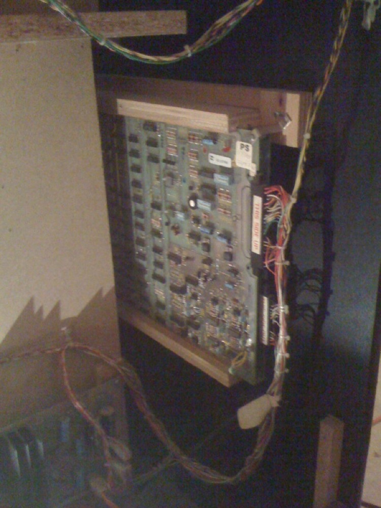
PCB Atari Tempest (vectoriel) — photo by thermionics, CC BY 2.0 (Wikimedia Commons).
Identification
| Field | Value |
|---|---|
| Manufacturer | Atari |
| Era | ~1979-1985 |
| Display | Vector XY (B&W or colour), no raster |
| Generator | DVG (Digital Vector Generator) then AVG (Analog Vector Generator) |
| Monitor | B&W XY (Asteroids, Battlezone) · colour XY = Wells-Gardner 6100 or Amplifone ("Quadrascan") |
Architecture (board side)
| Block | Element | Role |
|---|---|---|
| CPU | MOS 6502 (@ ~1.5 MHz) | game logic; often a 2nd 6502 dedicated to sound |
| Vector generator | DVG then AVG | reads a vector list (display list) in RAM and drives the monitor's X/Y DACs + intensity |
| Math Box (Star Wars, Battlezone, Red Baron) | bit-slice multiplier (AM2901) | computes the 3D projection of the vectors in real time |
| Sound | POKEY (× n) / TIA / discrete | effects + music |
The principle: instead of a TV (raster) scan, the board sends the monitor X/Y coordinates and an intensity; the beam traces segments directly between points — hence the sharp, bright lines of Asteroids, Tempest, Star Wars, Battlezone.
DVG vs AVG
| Generator | Intensity | Colour | Games |
|---|---|---|---|
| DVG (Digital Vector Generator) | fixed (on/off) | B&W | Lunar Lander, Asteroids, Asteroids Deluxe, Battlezone, Red Baron |
| AVG (Analog Vector Generator) | variable (per-vector brightness) | colour possible | Tempest, Space Duel, Gravitar, Black Widow, Star Wars, Major Havoc, Quantum |
The AVG is the major evolution: each segment can have its own brightness and colour (gradients, depth cueing), impossible on the DVG.
The "Math Box" (3D games)
Battlezone (1980) and especially Star Wars (1983) add a Math Box: a small AM2901 bit-slice calculator that performs the 3D projection's multiplies/divides far faster than the 6502 — which is what makes Star Wars' wireframe flight possible.
The vector monitor (the heart of the matter)
A vector game needs a dedicated XY monitor (not a raster one):
- B&W XY: Asteroids, Battlezone, Lunar Lander.
- Colour XY: Wells-Gardner WG6100 or Amplifone — Atari branded them "Quadrascan". These are the most fragile and the #1 source of faults.
An XY monitor cannot simply be replaced by an LCD: you need either a repaired real XY CRT or an XY→raster converter (community solutions).
The 13″ colour Amplifone — its manufacturer's manual, with figures at last ✅
This page has named the Amplifone from the start without giving a single figure. Here is its manual: ATARI 13-Inch Color X-Y Display, TM-222, 1st printing, 42 pp., part A200003.
ⓘ The manual says who built it, and it was not Atari: "This color X-Y display has been built to Atari specifications by Amplifone, Inc."
⚠️ And it has no chassis. "This display is not contained within a separate chassis; instead, the printed-circuit board (PCB) and the cathode-ray tube assembly (CRT) are separately mounted inside the game cabinet." ⓘ So you do not "pull" this monitor the way you pull a Wells-Gardner chassis: the board and the tube come out separately. Signals arrive on a 15-pin harness wired to the Deflection PCB.
| Item | What the manual writes |
|---|---|
| Mains input | ⚠️ 50 VAC RMS, centre tapped (25-0-25), +10 % / −15 % |
| X amplifier input | 16 V peak-to-peak (±8 V) for 10.5″ of deflection |
| Y amplifier input | 12 V peak-to-peak (±6 V) for 8″ of deflection |
| Z amplifier drive | +3.5 V for maximum intensity · 1.0 V for black level |
| Input impedances | X 3.3 kΩ · Y 2.2 kΩ · Z 2.2 kΩ |
| Z bandwidth | 8 MHz at −3 dB |
| EHT | 19.5 kV ⓘ at zero beam current |
| Factory adjusted | brightness, high-voltage adjustment, all bias and drive adjustments for the Z amplifiers |
| ⚠️ Operator adjustable | ⚠️ focus, and nothing else |
ⓘ Deflection is specified in inches, not in output volts — 16 Vpp gives 10.5″ in X, 12 Vpp gives 8″ in Y. ⓘ That is a way of specifying you do not see on a raster set, and it states the tube's useful format in passing: 10.5″ × 8″.
ⓘ EHT "at zero beam current" is the same measurement convention as the Electrohome G07 (22.5 to 25.5 kV measured at zero beam current).
⚠️ \"Quadrascan\": this wiki wrote it of the Amplifone, its manual does not
This page said colour XY is "Wells-Gardner WG6100 or Amplifone — Atari sells them under the name Quadrascan".
⚠️ The word "Quadrascan" does not appear once in the Amplifone manual. It does appear in the very title of the two other manuals archived here: the Wells-Gardner Quadrascan Color X-Y Display (Atari ref. 92-053) and the Electrohome G05 Monochrome X-Y Monitor "Quadrascan".
ⓘ This wiki does not conclude that Atari never used the name for the Amplifone — an absence in one document proves no absence everywhere. ⚠️ But it stops asserting it: of the three monitors, two carry the name on their cover, the third carries it nowhere.
The original manuals of the vector range ✅
38 Atari documents are archived here for this range — ⓘ the same TM series as the rest of the catalogue → Atari before the microprocessor.
16 documents with no reference legible on the title page
- Asteroids Deluxe Drawing Package Supplement — 8 pp.
- Asteroids Deluxe Schematics — numérisation 2 — 8 pp.
- Asteroids Deluxe Schematics — numérisation 3 — 8 pp.
- Asteroids Drawing Package Supplement — 8 pp.
- Asteroids Operation, Maintenance and Service Manual with illustrated parts lists — 47 pp.
- Asteroids Schematics — 8 pp.
- Asteroids Schematics — numérisation 2 — 8 pp.
- Asteroids Schematics — numérisation 3 — 8 pp.
- Battlezone Conversion Instructions — 4 pp.
- Battlezone Page 1 Wiring diagram and RegulatorAudio schematic — 1 pp.
- Battlezone Self-test procedure — 1 pp.
- Major Havoc Operator Manual — 19 pp.
- Major Havok — 7 pp.
- Tempest — 69 pp.
- The Adventures of Major Havoc — 34 pp.
- The Adventures of Major Havoc — 45 pp.
The Tempest Troubleshooting Guide — the document that was missing ✅
TM-195, \"Complete with Signatures and Memory Map\"
ⓘ It is neither the game's technical manual nor its schematics: it is a third document, and it is the one that carries the signatures. ⚠️ It did not ship with the cabinet.
ⓘ Atari itself names the four parts of the complete set in its copyright notice: "this troubleshooting guide, the technical manual, its accompanying schematic diagrams, and the monitor manual".
| Chapter | Contents |
|---|---|
| 1 | Memory map |
| 2 | Watchdog |
| 3 | ⓘ Troubleshooting using the CAT Box — address and data lines, RAM, option switch inputs, custom audio I/O chips, player inputs and encoder wheel, LED and coin counter outputs |
| 4 | ⚠️ Troubleshooting with signature analysis — clock and reset, address lines, address decoder, ROM and data lines, ⓘ Math Box |
✅ And it gives what no explanation replaces: where the three probes go, test by test, the expected signature pin by pin, and two sanity checks on the set-up — probe on ground → 0000, probe on +5 V → 0001.
⚠️ But +5 V does not always give 0001: in the ROM test set-up it must give 7A70. ⓘ A signature means nothing outside its set-up — which is why the guide restates the settings before every table. → PCB fault-finding
⚠️ The signatures are not written in hexadecimal
ⓘ Measured across TM-195's 27 table rows: the alphabet is exactly
0 1 2 3 4 5 6 7 8 9 A C F H P U — the sixteen symbols of Hewlett-Packard signature
analysis, shown on the CAT Box's seven-segment displays.
⚠️ 18 of the 27 values cannot be written in hexadecimal: 0PC5, 270P, HPP0, HAP7,
755P, 2A8P, C4U4, H1U9… ⓘ Anyone expecting hex will read 0PC5 as an instrument
fault.
Common faults
| Symptom | Likely cause | Lead |
|---|---|---|
| Distorted / missing lines | XY deflection stage, cold joints | Reflow, deflection diagnosis |
| Dead screen (HV ok) | Vector stage / dead caps | Recap + diagnosis |
| Fixed bright dot ("spot") | Spot-killer / deflection failure | ⚠️ power off (phosphor burn risk), repair first |
| Wrong colours (WG6100) | Colour stage / convergence | Adjustments, recap |
| Board: no image | Power, DVG/AVG, contacts | Diagnosis |
High voltage (CRT) & spot-killer
An XY monitor = a high-voltage CRT: discharge the tube before any work. If a fixed, very bright dot appears, cut power immediately — the stationary beam burns the phosphor in seconds. The spot-killer circuit is meant to prevent this; if it fails, that's the priority.
Repair & preservation
- Recap + reflow of the XY monitor (WG6100 / Amplifone) — the central topic; capacitor kits and repro deflection boards exist (active community).
- DVG/AVG diagnosis for board-side drawing faults.
- Reference emulation: MAME (Atari vector drivers).
- FPGA / MiSTer: cores exist for several Atari vector games (Asteroids, Lunar Lander, Battlezone, Tempest, Black Widow…) — the vector render is rebuilt and shown as raster.
EPROM repair
6502 (Asteroids, Tempest) / 68000 (Star Wars) program in 2716 / 2732 / 27128 by era. The heart is the vector generator (DVG/AVG) + Math Box (Star Wars), not the EPROM — see the architecture above.
Modernisation & mods
The common ground for every JAMMA board
Video, power, control panel and upscalers depend on the cabinet rather than the board: everything is centralised in Modernising a cabinet. To run the board outside a cabinet (at home, on a display): supergun.
- Storage 🟡: the game lives in EPROM/mask ROM on the board. Changing or restoring a game means reprogramming the EPROMs (and, for a mask ROM, using a pinout adapter) → EPROM method.
- Media preservation: replacing the original storage, multicarts, ODEs and modern options by family → PCB preservation hub.
- Scan rate 📺: not applicable — VECTOR display. There is no line-by-line scanning and no horizontal frequency: the beam draws the segments directly. These machines require a vector monitor and cannot be connected to a raster chassis, a tri-sync or an upscaler. See the repair section for the deflection electronics.
- FPGA / emulation: see the Emulation & FPGA section below.
Repair (technician)
- ⚠️ High-voltage XY vector monitor (WG 6100 / Amplifone) → CRT safety; a static spot burns the phosphor (cut immediately).
- DVG / AVG: distorted/missing lines = the vector generator (digital DVG or analog AVG) + deflection; the Amplifone and WG6100 have known HV faults (deflection transistors) → recap + diagnose.
- Slapstic (protection) on some games: check before suspecting the logic.
- Sound: dedicated 2nd 6502 + POKEY — diagnose the sound stage.
→ Methods: CRT safety · PCB fault-finding · Recap · EPROM
Expected clocks — measurement table ✅
Values extracted from the MAME sources for this platform. On a scope or frequency counter, a clock that is missing or off-value points straight at the crystal, the divider or the chip at fault — the fastest starting point on a dead board.
| Component | Expected clock | Role |
|---|---|---|
| M6502 | 1.512 MHz | CPU |
How to read this table
Several values for one component = several board variants in this family (or several instances of the chip clocked differently). These frequencies are those of the clock signal at the component's input, not of its original crystal — on many boards the clock is divided down from a single master crystal.
Archived original schematics ✅
Manufacturer schematics for games in this family, archived locally (so they do not depend on a third-party site staying up). They give the board's real functional breakdown: clock tree, address decoding, video stage, sound stage, power supply — exactly what you need to trace a missing signal back to its source.
- Battlezone — full schematic (PDF)
Scope and limits
A schematic applies to the game and revision named. Within one family the general breakdown (buses, decoding, sound/video stages) carries over from board to board, but component references and custom chip pinouts do not transpose between titles. Use it as a map of the logic, not as a cross-reference table.
Source: the Arcade Game Manuals collection on the Internet Archive. Manufacturer documents with no explicit licence, kept here for preservation (machines out of service for over 25 years).
DIP settings ✅
1 games on this platform, settings extracted from the MAME sources (INPUT_PORTS_START blocks). The Position column gives the switch's physical reference on the board (SW2:!3,!4 = bank SW2, levers 3 and 4) — which is what lets you set it up without the paper manual. Games are sorted by MAME set name.
DIP settings — MAME set asterock
| Setting | Position | Options (default in bold) |
|---|---|---|
| Language | SW:1,2 | English · French · German · Italian |
| Lives | SW:3,4 | 2 · 3 · 4 · 5 |
| Records Table | SW:5 | Normal · Special |
Check against your own board
These settings apply to the game and revision described by MAME. One title may have several DIP sets depending on region or revision, and some systems use soft-dips (settings in memory, via the test menu) rather than physical switches. In case of a discrepancy, the board's silkscreen and the test menu are authoritative.
See also: DIP reference · game manuals
Procedure — a dead board, step by step ✅
What this adds
The general method lives in PCB diagnosis. This is its application to this platform: the same order, but with the values actually expected here, so you do not have to go back and forth.
Tools: multimeter, oscilloscope (or frequency counter), current-limited bench supply, desoldering braid. → Tooling
If the board is still in a cabinet
A CRT holds its charge with the machine unplugged. → CRT safety
1. Inspection, power off. Corrosion, cut tracks, oxidised EPROM legs, leaking SMD capacitors, dubious earlier repairs.
2. The connector, before anything else. A large share of "dead boards" are a contact problem, not a fault. Clean the contacts with isopropyl alcohol and reseat — not with an abrasive eraser on a gold edge, which takes the plating off and brings the problem back worse. It costs two minutes and settles the question.
3. Power, measured on the board. Aim for +5.0 V measured as close as possible to where power reaches the board — not at the PSU output: the drop is in the loom, and that is exactly what makes a board boot on the bench and not in the cabinet. Where you probe depends on this board's connector — JAMMA edge, JVS loom or a proprietary harness — plenty of makers kept one long after JAMMA arrived — see Identification above. → Wiring Check −5 V and +12 V too if the sound stage uses them. Suspected short: bring it up current-limited and find the hot spot.
4. /RESET. It must release after power-up. Held low = the CPU never starts. A 1–2 Hz loop is not the reset circuit, it is the watchdog: the CPU is crashing at boot, so look at the bus, not at the reset.
5. Clocks — the values expected on this platform.
- M6502 → 1.512 MHz (CPU)
No clock on the M6502 (1.512 MHz) and there is no point measuring anything else: the fault is the crystal, the divider, or the chip itself. That single measurement splits a dead board in two.
6. Bus. Activity on the main CPU's address lines tells you whether it is running or frozen. Frozen with good clocks and good reset → work RAM, bus buffers, ROMs.
7. It boots but the picture or the sound is wrong — that is another job: see Common faults on this page, then signal tracing.
Photos / assets
(To add: WG6100/Amplifone monitor, vector board, DVG/AVG, Math Box.)
Sources & attribution
-
Photo PCB Atari Tempest (vectoriel) — thermionics, CC BY 2.0, Wikimedia Commons — https://commons.wikimedia.org/wiki/File:Arcade_PCB_Tempest.jpg
-
Wikipedia — Vector monitor / Atari, Inc. / Asteroids / Tempest / Star Wars (1983 video game) — CC-BY-SA — https://en.wikipedia.org/wiki/Vector_monitor
- MAME — Atari vector drivers (
atari/) — to reference

Review & corrections
How this space is used
Spotted a wrong value, an outdated procedure, a chip reference that does not match your board? Say so here, with what you observed (model, board revision, serial number, measurement). Every report is cross-checked against a source before anything changes — an unverifiable correction is published as “reported by …, not cross-checked” rather than silently applied.
Reading is open to everyone; posting requires signing in with Discord. Reports from the wiki's declared reviewers are handled first; anyone else's are read too, but go through a human before anything is changed.