Sega NAOMI
Sega arcade platform (1998), Dreamcast architecture with more memory. It runs in a candy cab via JVS (modern serial I/O), and comes in cartridge, GD-ROM (via DIMM board) and netboot forms. An often-misunderstood point: the DIMM board battery — not a "suicide" as brutal as the CPS-2's.
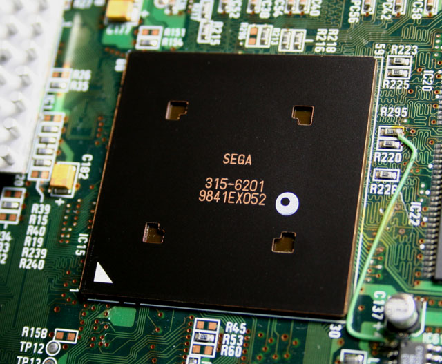
Identification
| Field | Value |
|---|---|
| Manufacturer | Sega |
| Year | 1998 (NAOMI 2: 2000) |
| Base | Dreamcast + more RAM (32/16/8 MB main/graphics/sound) |
| Media | ROM cartridge, GD-ROM (via DIMM), netboot (NetDIMM) |
| I/O | JVS (JAMMA Video Standard, serial) |
| Multiboard | 3-4 boards per game |
Architecture
| Block | Chip | Clock | Role |
|---|---|---|---|
| CPU | Hitachi SH-4 | ~200 MHz | + FPU/vector unit |
| GPU | NEC/VideoLogic PowerVR2 (CLX2) | ~100 MHz | Tile-Based Deferred Rendering |
| Sound | ARM7 + Yamaha AICA | 64 voices | |
| RAM | 32 MB main + 16 MB VRAM + 8 MB sound | 2× the Dreamcast (hence "superior" ports) |
NAOMI = New Arcade Operation Machine Idea. Architecture identical to the Dreamcast but with more RAM — hence near-perfect arcade↔home conversions (often superior on the arcade side). Region/language set at the BIOS.
Media & loading
- ROM cartridge: the simplest, no critical battery.
- GD-ROM: GD drive + DIMM board (RAM). At boot, the game is copied from the GD to the DIMM.
- Netboot (NetDIMM): loads the game from a PC over the network → no GD or cartridge.
The DIMM board battery ✅
Sega's NAOMI GD-ROM service manual (420-6620-02) describes two separate batteries.
On the DIMM board: a rechargeable pack that wears out. It is what makes the game's load time from the GD-ROM vary:
"Readout time varies depending on the charge of the DIMM board battery pack. It may be as long as several minutes when the power is connected for the first time or reconnected after a long-term power disconnection."
- ⚠️ It is not a primary cell, it is a rechargeable pack: "After discharging/recharging of about 500 times, the maximum charge may be only 70 to 80 % of the initial charge". Sega derives a service life of about 16 months for a cabinet switched on and off every day.
- Symptom given by the manual: loading takes longer than before. ⓘ It mentions neither losing the game nor a locked board.
- Part: BATTERY PACK CGR-B/241A, Sega part 401-0076. ⚠️ The manual forbids charging it with an external charger ("any battery charger is not usable for this battery pack"), soldering it, or sealing it in without ventilation.
On the NAOMI main board: a CR2032 coin cell (Sega 401-0054), under the ROM/DIMM board. ⚠️ The manual says: "Except for special cases such as using up the battery, etc., do not perform this work."
ⓘ What the manual does not say: this page claimed the DIMM battery also keeps the game's "key". The manual makes the key a removable chip (key chip) inserted in the DIMM board case, with no written link to the battery; the claim is withdrawn.
Netboot (NetDIMM) — step by step
Netboot is the NAOMI preservation route: you send the game image from a PC into the DIMM board's RAM over Ethernet — no GD or cartridge. Principle and steps:
- Required hardware: a network DIMM board (NetDIMM) (not all are — check for the Ethernet port), the NAOMI, a JVS I/O, and the appropriate security PIC (per-game key; community setups bypass this point).
- DIMM firmware: the DIMM must have a netboot-capable firmware (flash it once if needed).
- Network: connect PC ↔ NetDIMM over Ethernet (crossover cable or switch). Set the IPs in the NAOMI system menu (the DIMM shows "Network booting…" / waits for the transfer).
- Transfer: on the PC, a send tool (community scripts like
triforcetools.py/naomi.py, or sending via emulators that talk to the NetDIMM) pushes the game image into the DIMM's RAM. - Launch: once the transfer finishes, the NAOMI boots the game from RAM. Thanks to the DIMM battery, the game stays loaded between power cycles — no need to re-send each time.
Why it's the best route
Netboot removes the GD drive (the wear point) and doesn't depend on a rare cartridge. Combined with a fresh DIMM battery, it's a reliable, silent setup. → See also ODE (GDEMU/MODE, netboot). (We describe the method; no ROM hosting.)
JVS (I/O)
The NAOMI uses JVS: serial I/O that replaces the parallel JAMMA wiring (sticks, buttons, coins via a JVS I/O board). ⓘ On the board side, the Sega manual connects the I/O board to CN5 with a USB cable (type A) — see the connectors. It's the standard for modern Sega cabinets; it can be driven/emulated (see JVS-adapter type projects).
Filter board connectors ✅
Per the service manual, chapter 2-2:
| Ref. | Role |
|---|---|
| CN1 | power, JST VL 8-pin: 2 = +3.3 V, 3 = +5 V, 4 = +12 V, 5-8 = GND |
| CN2 | power, JST VL 6-pin: 2 = +3.3 V, 3 = +5 V, 4-6 = GND |
| CN3 | video, mini D-sub 15-pin |
| CN4 | stereo audio, RCA (red = right, white = left) |
| CN5 | STANDARD I/O — USB type A, "connected to I/O BD via USB cable" |
| TORX194 / TOTX195 | optical fibre, link between several NAOMIs |
| PSW1 / PSW2 | TEST and SERVICE buttons |
ⓘ A JVS cabinet is required: for a JAMMA cabinet, the manual says to "prepare the modification parts (power supply, I/O board, audio amplifier, etc.)".
⚠️ Sending a board for repair: do not remove the key chip
The manual asks for the NAOMI case, the DIMM case — "Do not remove the key chip but leave it attached" — and the GD-ROM drive without its disc to be shipped together, in their original cartons, with a symptom report and the game's name.
Cabinets
- Naomi Universal Cabinet (dedicated cabinet).
- In a candy cab (Astro City & co.) via a JVS I/O board + suitable power.
NAOMI 2 (2000)
A high-end evolution of the NAOMI for heavy 3D: it adds a second SH-4 dedicated to geometry and two PowerVR2 graphics engines (+ an ELAN for transform/lighting), i.e. far more polygon power — while staying compatible with the NAOMI's cartridge/GD-ROM format and JVS I/O.
- Games: Virtua Fighter 4 (+ Evolution/Final Tuned), Club Kart, Wild Riders, Virtua Striker 3, Beach Spikers, Soul Surfer…
- Preservation: the same routes as the NAOMI (imaged GD-ROM, netboot, DIMM battery), handled by Flycast/Demul for emulation.
- Not to be confused with the Hikaru (another contemporary high-end 3D, different hardware).
Common faults
| Symptom | Likely cause | Lead |
|---|---|---|
| Loading takes longer than before | DIMM battery pack at end of life (~500 cycles) | replace it — detail |
| An ERROR or CAUTION message at start-up | see the manufacturer's table | → Error messages |
| No image / crash | Power, caps, contacts | Base diagnosis |
| I/O not responding | JVS I/O board / wiring | Check JVS, I/O power; JVS TEST in the system menu |
System error messages ✅
The service manual lists the messages shown at power-on and when leaving test mode — the game does not start while they are present:
| Message | Cause given by the manual | Remedy |
|---|---|---|
| ERROR 01 — game not acceptable by main board | ROM or DIMM board badly connected; NAOMI 2 software on a NAOMI board | reconnect; a NAOMI 2 game needs a NAOMI 2 main board |
| ERROR 02 | game of a country version incompatible with the main board | game of the right region; ⚠️ cannot be changed in test mode |
| ERROR 03 — board malfunctioning | main board serial number unreadable | send for repair, DIMM fitted |
| ERROR 04 | DIMM board serial number unreadable | send the NAOMI board with the DIMM |
| ERROR 21 | data loaded from GD-ROM to DIMM corrupted; or NAOMI 2 disc on a NAOMI board | check the GD cable, the disc's condition |
| ERROR 22 | main board gets no response from the DIMM | reconnect DIMM and GD interface board; otherwise replace them |
| ERROR 23 | GD drive cover open | close it |
| ERROR 24 | GD disc not recognised | reinsert it; check for scratches and dirt |
| ERROR 25 | GD drive not accessible; or cover open | reconnect GD cable and drive power; otherwise replace the drive |
| ERROR 26 — option board malfunctioning | key chip not recognised | the right chip for this disc, firmly inserted |
| ERROR 27 — DIMM memory is not enough | DIMM memory insufficient or badly seated | add the required memory; reseat it |
| CAUTION 51 | CABINET TYPE wrong for the game | correct it in SYSTEM ASSIGNMENTS |
| CAUTION 52 | 15 kHz-only game output at 31 kHz | monitor to 15 kHz and filter board DIP 1 ON |
| CAUTION 53 | 31 kHz-only game output at 15 kHz | monitor to 31 kHz and DIP 1 OFF |
⚠️ The manual adds: "If an error message appears, immediately disconnect the power to the cabinet."
ⓘ Filter board DIP 1: OFF = 31 kHz, ON = 15 kHz
Stated frequencies: 15.85 kHz / 31.69 kHz. DIP 2 and 3 OFF "unless otherwise specified". ⚠️ As shipped, the setting depends on the game sold with the board: the manual asks you to check it before installation.
Mods & preservation
- Netboot (NetDIMM): the modern solution — no GD or critical battery; loads from a PC. → ODE (GDEMU/MODE, netboot)
- GD-ROM emulation / SD storage (depending on solutions).
- Replace the DIMM battery with a holder.
- Emulation: Flycast / Demul (Dreamcast lineage) + MAME. No FPGA/MiSTer core (SH-4 + PowerVR2 out of budget).
Manual (archived)
- 📘 Service manual — NAOMI GD-ROM System (Sega, 420-6620-02) — the board.
- 📘 Manual — Sega NAOMI Universal Cabinet — the dedicated cabinet, not the board → cabinet page.
Modernisation & mods
The common ground for every JAMMA board
Video, power, control panel and upscalers depend on the cabinet rather than the board: everything is centralised in Modernising a cabinet. To run the board outside a cabinet (at home, on a display): supergun.
- Battery 🟢: a save battery is fitted (settings/counters/RTC). ⚠️ On this platform, a dead battery does NOT kill the game — it is a leaking battery that corrodes traces. Check and replace it before it leaks → save batteries.
- Optical storage 🟡: the drive is the number-one wear part. Modern routes: an ODE, netboot, or replacement by flash storage depending on the platform → PCB preservation hub.
- Scan rate 📺: ~32.83 kHz / 61.7 Hz — high resolution (VGA class), ⚠️ you need a 31 kHz / tri-sync monitor; a 15 kHz chassis is incompatible → tri-sync and upscalers.
(Computed from the MAME sources —
sega/naomi.cpp— pixel clock ÷ htotal.) - FPGA / emulation: see the Emulation & FPGA section below.
Repair (technician)
- DIMM board (GD-ROM / NetDIMM): a worn rechargeable pack lengthens loading from the GD-ROM — detail and part number. ⓘ The Sega manual says nothing about a battery on cartridges: that point remains to be sourced (backup batteries).
- Key chip (GD-ROM): when not recognised it gives ERROR 26 — the right chip, firmly inserted, before blaming the main board.
- GD-ROM: drive/laser = a weak point → ODE mods (GDEMU).
- Sound: ARM7 + AICA — diagnose the sound stage. Capacitors: recap.
→ Methods: PCB fault-finding · Recap · Backup batteries · Traces & vias
DIP settings ✅
2 games on this platform, settings extracted from the MAME sources (INPUT_PORTS_START blocks). The Position column gives the switch's physical reference on the board (SW2:!3,!4 = bank SW2, levers 3 and 4) — which is what lets you set it up without the paper manual. Games are sorted by MAME set name.
DIP settings — MAME set alpilota
| Setting | Position | Options (default in bold) |
|---|---|---|
| Monitor | SW1:1 | 31 kHz · 15 kHz |
DIP settings — MAME set naomi_mie
| Setting | Position | Options (default in bold) |
|---|---|---|
| Monitor | SW1:1 | 31 kHz · 15 kHz |
Check against your own board
These settings apply to the game and revision described by MAME. One title may have several DIP sets depending on region or revision, and some systems use soft-dips (settings in memory, via the test menu) rather than physical switches. In case of a discrepancy, the board's silkscreen and the test menu are authoritative.
See also: DIP reference · game manuals
Procedure — a dead board, step by step ✅
What this adds
The general method lives in PCB diagnosis. This is its application to this platform: the same order, but with the values actually expected here, so you do not have to go back and forth.
Tools: multimeter, oscilloscope (or frequency counter), current-limited bench supply, desoldering braid. → Tooling
If the board is still in a cabinet
A CRT holds its charge with the machine unplugged. → CRT safety
1. Inspection, power off. Corrosion, cut tracks, oxidised EPROM legs, leaking SMD capacitors, dubious earlier repairs.
2. The connector, before anything else. A large share of "dead boards" are a contact problem, not a fault. Clean the contacts with isopropyl alcohol and reseat — not with an abrasive eraser on a gold edge, which takes the plating off and brings the problem back worse. It costs two minutes and settles the question.
3. Power, measured on the board. Aim for +5.0 V measured as close as possible to where power reaches the board — not at the PSU output: the drop is in the loom, and that is exactly what makes a board boot on the bench and not in the cabinet. Where you probe depends on this board's connector — JAMMA edge, JVS loom or a proprietary harness — plenty of makers kept one long after JAMMA arrived — see Identification above. → Wiring Check −5 V and +12 V too if the sound stage uses them. Suspected short: bring it up current-limited and find the hot spot.
4. /RESET. It must release after power-up. Held low = the CPU never starts. A 1–2 Hz loop is not the reset circuit, it is the watchdog: the CPU is crashing at boot, so look at the bus, not at the reset.
5. Clocks. There is no measurement table for this platform — MAME's sources yield nothing usable for it. Any frequency quoted under Architecture on this page serves as a marker; otherwise compare against a working board rather than against a number: an invented value condemns healthy parts. → PCB diagnosis
6. Bus. Activity on the main CPU's address lines tells you whether it is running or frozen. Frozen with good clocks and good reset → work RAM, bus buffers, ROMs.
7. It boots but the picture or the sound is wrong — that is another job: see Common faults on this page, then signal tracing.
Photos / assets
(To add: NAOMI board, DIMM board + battery, ROM cartridge, GD drive, JVS I/O.)
Archived manufacturer documentation ✅
Manufacturer documentation archived locally. ⓘ The NAOMI GD-ROM document is a service manual (Service Manual, 420-6620-02, 1st printing June 01): connectors, batteries, error messages, test mode. ⚠️ It contains no schematics.
- NAOMI GD-ROM System Service Manual — PDF
Status
Manufacturer documents with no explicit licence, kept for preservation (machines out of production for decades).
Sources & attribution
- Wikipedia — Sega NAOMI (Dreamcast base, SH-4, media, multiboard, Naomi 2) — CC-BY-SA — https://en.wikipedia.org/wiki/Sega_NAOMI
- System16 — Sega NAOMI Hardware — to reference — https://www.system16.com/hardware.php?id=709
- Netboot / JVS documentation — to reference
Image:
-
naomi.jpg— Yaca2671, CC BY-SA 3.0 — https://commons.wikimedia.org/wiki/File:NAOMI_PowerVR2.jpg

Review & corrections
How this space is used
Spotted a wrong value, an outdated procedure, a chip reference that does not match your board? Say so here, with what you observed (model, board revision, serial number, measurement). Every report is cross-checked against a source before anything changes — an unverifiable correction is published as “reported by …, not cross-checked” rather than silently applied.
Reading is open to everyone; posting requires signing in with Discord. Reports from the wiki's declared reviewers are handled first; anyone else's are read too, but go through a human before anything is changed.