Sega NAOMI Universal Cabinet
The standard cabinet dedicated to the NAOMI (1998+): a Sega "universal" cabinet built to host the NAOMI board (and its carts/GD-ROMs) with JVS I/O and a 31 kHz monitor. Sega's official move into the JVS era.
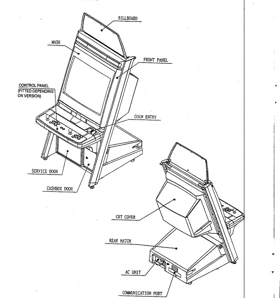
Identification
| Field | Value |
|---|---|
| Manufacturer | Sega |
| Year | 1998 → (NAOMI era) |
| Type | Universal cabinet (system-dedicated upright) |
| System | Sega NAOMI (cartridge or GD-ROM via DIMM) |
| Screen | tri-sync CRT (accepts NAOMI 31 kHz) |
| I/O | JVS (modern serial standard) |
Technical notes
- Built for the NAOMI: board bay + JVS I/O board + video wiring compatible with 31 kHz (the NAOMI outputs VGA/31 kHz by default).
- JVS: no 56-pin JAMMA edge for the game → serial JVS I/O connected to the NAOMI's JVS board (a Sega 838-xxxx I/O board).
- GD-ROM support: for GD-ROM games, add the GD-ROM drive + DIMM board (decompression RAM) — see the NAOMI page.
- A "universal" cabinet: several artwork revisions/variants depending on games and regions.
⚡ Connector & power
| Aspect | Value |
|---|---|
| Year | 1999 — 29″; the manual titles it "U/R TYPE" (upright) |
| Connector | JVS (serial) — no JAMMA for the game (Sega JVS I/O board) |
| Video | 31 kHz (NAOMI VGA output); EU chassis Sanwa 29E31S or Nanao MS-2932-S |
| System | NAOMI (cartridge / GD-ROM + DIMM) |
| Power | Sun 400-5397-1 PSU (close to a PC ATX), 230 VAC, 1.4 A in the archived manual; Hard*Candy gives a 110 V AC input (3-pin AMP Universal connector) — see below |
| Weight | ~117 kg |
| Consumption | 322 W max. (archived manual) |
(Sources: Arcade Otaku + Hard*Candy + archived NAOMI Universal manual.)
→ Detailed wiring: a JVS cabinet → see JVS wiring and the JVS I/O board (Sega 837-13551, or 838-13683 JVS↔JAMMA to reuse a candy cab's JAMMA panel).
What the archived manual says ✅
A composite document, and a cabinet shipped with Zombie Revenge
The archived manual (86 pages) combines three things: a Sega Enterprises, Ltd. cover — NAOMI Universal Cabinet, U/R TYPE, Owner's Manual, MANUAL NO. 420-6460-01, 1st printing —, coin mech fitting instructions numbered 420-6455-C220, then the UK service manual from Sega Amusements Europe (New Malden).
ⓘ Its accessories list is that of a "ZOMBIE ZONE" / ZZN kit — Zombie Revenge — and it cites a "SERVICE MANUAL NAOMI UPRIGHT, 420-6455-01UK", the reference the Sega Marine Fishing manual calls the "Naomi Cabinet manual". ⚠️ This wiki does not conclude that the archived UK pages are that 420-6455-01UK: the document does not say so outright.
Every value below was re-read from the image.
| Specification (SPECIFICATIONS box) | Value |
|---|---|
| Footprint | 76 (W) × 98 (D) cm |
| Height | 175 cm |
| Weight | approx. 117 kg |
| Power, max. | 322 W |
| Rated voltage / current | 230 VAC · 1.4 A |
| Operating temperature | 5 – 40 °C |
⚠️ Two heights in the same manual
The SPECIFICATIONS box gives 175 cm. The table in the Name of parts chapter gives 180 cm for the cabinet and 210 cm "When Assembled" — billboard fitted —, for the same 76 × 98 footprint. ⓘ This wiki publishes all three without choosing between 175 and 180.
⚠️ 230 V in the manual, 110 V at Hard*Candy
The archived manual, UK edition, gives 230 VAC. The Hard*Candy data used above gives a 110 V input. ⓘ Both are published: read the electrical plate on your own cabinet before plugging it in.
Fuses (chapter 3.13) — "Only replace the fuse once you have removed the cause of its failure":
| Part number | Location | Type | Qty |
|---|---|---|---|
| 514-5078-3150 | stereo amp, F1 and F2 | 5 × 20 mm ceramic slow-blow 3.15 A | 2 |
| 514-5078-4000 | switching regulator, F1 | 5 × 20 mm ceramic slow-blow 4 A | 1 |
| 514-5078-5000 | IEC inlet, F1 | 5 × 20 mm ceramic slow-blow 5 A | 1 |
| 514-5078-5000 | connector board, F1 | 5 × 20 mm ceramic slow-blow 5 A | 1 |
ⓘ The monitor has its own fuses, referred to its manual — the kit lists a "SERVICE MANUAL MS 2932 (DEPENDING ON VERSION)".
⚠️ The 5 V and 3.3 V adjustments: leave them as set
The power supply carries two potentiometers, 5V ADJ and 3.3V ADJ, and a POW lamp. The manual warns: "The V. ADJs have been set at the factory. Be sure to use the V.ADJs as set at time of shipment. Changing the setting without a justifiable reason can damage the IC Board and cause malfunctioning." → Power supplies in cabinets
Periodic inspection (chapter 6):
| Item | Check | Interval |
|---|---|---|
| Cabinet | adjusters' contact with the floor | daily |
| Monitor | cleaning the CRT face · settings | weekly · monthly |
| Game board | settings check | monthly |
| Control panel | input test | monthly |
| Sound | sound test, volume adjustment | monthly |
| Coin selector | coin insertion test · cleaning | monthly · tri-monthly |
| Power cord | condition | annually |
| Interior | cleaning ("Do Not use water jet") | annually |
ⓘ In the installation kit: a spare 250 cm JVS type A-B cable (600-7141-250), the tamperproof M4 and M6 wrenches, and a spare 5 A fuse.
Common faults
The manual's troubleshooting table (chapter 3.12) covers the cabinet only — "If a problem occurs, first check the wiring connections":
| Symptom | Cause given by the manual | Remedy |
|---|---|---|
| Nothing happens at the main switch | no mains; wrong voltage; AC unit protection (fuse) tripped by an overcurrent | plug in; check the voltage; remove the cause of the overcurrent before resetting the protection |
| Wrong colours | monitor adjustment | adjust — monitor manual supplied |
| Picture sways or shrinks | incorrect supply voltage | check the supply and voltage |
| No sound | volume; board or amp; connector | set the volume (3.7); sound test; check base → speaker connection |
| Fluorescent lamp off | lamp to replace; connector unplugged | replace; check connections (3.9) |
ⓘ What belongs to the NAOMI board — cartridge, DIMM, GD-ROM, battery — is not a cabinet fault: → Sega NAOMI.
Procedure — a cabinet that will not start ✅
There is a CRT in this cabinet
The tube stays charged with the cabinet unplugged, and the anode cap is the first thing your hand meets behind the monitor. Discharge it, work with one hand, and never alone if you can help it. → CRT safety
What this adds
Ordered for a cabinet, not for a board: mains, low-voltage supply, loom, monitor, then the game. The overwhelming majority of "dead cabinets" are dead for a reason that has nothing to do with the PCB — which is why the board comes last here.
1. Mains, and what sits between it and the cabinet. The switch, the fuse or breaker, the isolation transformer if there is one. A cabinet that shows no sign of life at all is almost never electronic.
2. The low-voltage supply — measured under load. Aim for +5 V where power reaches the board — the JAMMA edge, or the JVS power connector, depending on the cabinet — with the game running, not on an idle bench. If the supply has an adjustment (most candy and JVS bricks do; the ATX brick in a PC cabinet does not), do it then and not before: set off-load, it leaves a board that boots and then glitches. With no adjustment the measurement still earns its keep — it tells you whether the supply holds. Check +12 V too, and −5 V if the board uses it: many do not, and an ATX brick does not provide it. → Cabinet power
3. The loom and the connector. Reseat, and check the grounds — a cabinet with a poor ground gives rolling picture, phantom inputs and noise, all at once, and none of it looks like a wiring fault. Connector on this cabinet: JVS (serial) — no JAMMA for the game (Sega JVS I/O board). → Wiring
4. The monitor. This page describes the monitor as: tri-sync CRT (accepts NAOMI 31 kHz). CRT: no picture but the tube is warm and there is EHT — that is sync or video, not the tube. No EHT at all — chassis. A picture that shrinks, wanders or shifts colour is a chassis recap, and on these monitors that is a scheduled job, not a repair.
5. Scan rate — the mismatch that breaks nothing. If the board's rate is not one the monitor accepts, you get no picture and nothing is faulty. Check what this cabinet takes against what the board puts out before opening anything. → Modernising a cabinet
6. The control panel. Microswitches and the loom, in that order. A single dead direction is a switch; a whole player dead is the loom or its ground. → Control panels
7. Coin mech and sound. Last, because they hide nothing: a mech that no longer registers is usually dirty or misadjusted, and silence with a good picture points at the amplifier and its supply rails.
Repair
- Monitor: 31 kHz tri-sync chassis → maintenance like the Nanao MS9.
- Power: Sega cabinet PSU → candy cab PSU. 5 V and 3.3 V adjustments to be left as factory-set (above).
- The game board is a separate machine, diagnosed on its own → Sega NAOMI.
Manuals (archived)
- 📘 NAOMI Universal manual (PDF)
(Source: Arcade Otaku Wiki, archived locally for preservation.)
Photos / assets
(To add: NAOMI Universal Cabinet, NAOMI bay, JVS I/O board, GD-ROM/DIMM.)
Repair & maintenance
Modernise (video, PSU, JVS, upscaler, PC/FPGA) → Modernising a cabinet. CRT monitor (discharge HV!) → CRT safety + Nanao MS8 / MS9 chassis · Sega candy PSU → PSU repair · recap → Recap.
Sources & attribution
- Arcade Otaku Wiki — Sega NAOMI Universal Cabinet — https://wiki.arcadeotaku.com/
- Internal page: Sega NAOMI (the hosted system)
Image:
-
naomi-universal-plan-manuel.png— drawing from chapter 3.3 Name of parts of the archived manual. ⚠️ Replaced on 13 September 2026 a Hard*Candy photo that showed a modified cabinet.
Review & corrections
How this space is used
Spotted a wrong value, an outdated procedure, a chip reference that does not match your board? Say so here, with what you observed (model, board revision, serial number, measurement). Every report is cross-checked against a source before anything changes — an unverifiable correction is published as “reported by …, not cross-checked” rather than silently applied.
Reading is open to everyone; posting requires signing in with Discord. Reports from the wiki's declared reviewers are handled first; anyone else's are read too, but go through a human before anything is changed.