Sega Master System (Mark III)
Sega's 8-bit console (1985, Mark III in Japan; Master System in export from 1986). A NES rival. Native RGB on the Model 1, FM sound on the Japanese models, and a cost-reduced Model 2 (composite only).
Identification
| Field | Value |
|---|---|
| Manufacturer | Sega |
| Release | 1985 (Mark III, JP) / 1986 (SMS, export) |
| Generation | 3rd (8-bit) |
| Revisions | Model 1 (RGB, card slot, ext.) · Model 2 (cost-reduced) · Mark III JP |
| Native video output | RGB (Model 1, DIN socket); composite/RF (Model 2) |
| Region / lockout | JP/export region + 50/60 Hz |
| Media format | Cartridge + Sega Card (Model 1) |
Architecture (detail)
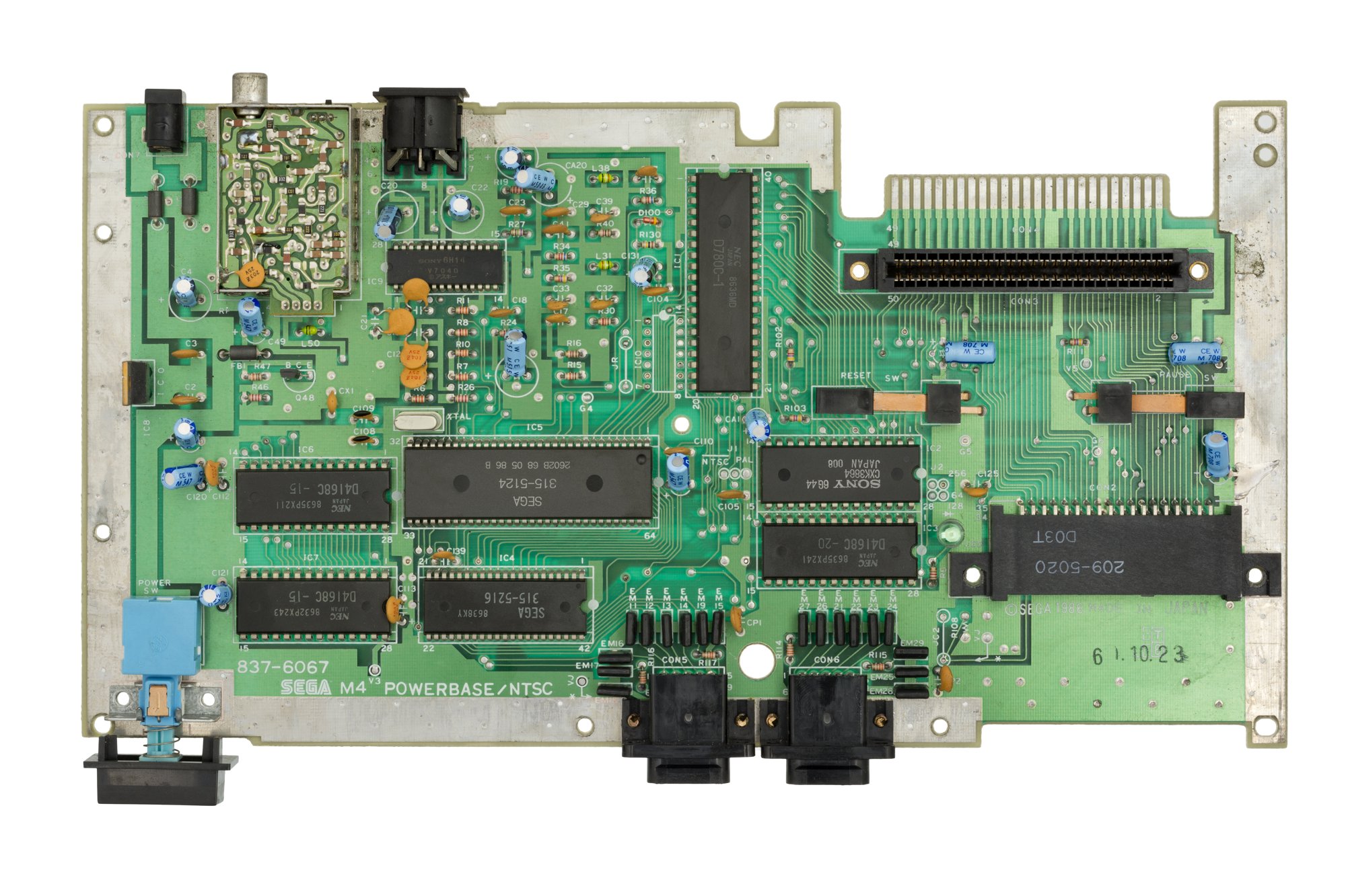
| Block | Chip | Clock | Notes |
|---|---|---|---|
| CPU | Zilog Z80 | 3.58 MHz | |
| Video (VDP) | Sega 315-5124 | Derived from the TMS9918; Mode 4: 256×192, 32 colours out of 64, 64 sprites (8/line) | |
| Sound | SN76489 (PSG) | 3 voices + noise; + YM2413 (FM, 9 voices) on Mark III / Japanese SMS | |
| RAM | 8 KB work + 16 KB VRAM | ||
| Media | Cartridge + Sega Card (Model 1 slot) | + Light Phaser, 3D glasses |
Revisions
- Model 1: native RGB (DIN), Sega Card slot, expansion port, LED, reset. The best for AV.
- Model 2: cost-reduced — composite/RF only (RGB needs a mod), no card slot, no reset.
- Mark III / Japanese Master System: FM sound (YM2413) stock.
Peripherals & built-in game
- Light Phaser: an optical gun (CRT only).
- SegaScope 3-D Glasses: active LCD-shutter glasses plugged into the card slot (Model 1) — stereoscopy on a few games (Space Harrier 3-D…).
- Sports Pad (trackball), Paddle Control, Rapid Fire Unit.
- Handle Controller (1989): a steering wheel that doubles as a flight stick — Super Monaco GP, After Burner, Ace of Aces.
- Sega Control Stick: an arcade-style joystick controller whose buttons are on the opposite side to those of the standard pad. The French source ties it to the Mark III.
- RF transmitter (Mark III): an optional accessory for wireless play, broadcasting the game to the television over a UHF signal. ⚠️ Documented on the Japanese Mark III only.
- ROM game (BIOS): many consoles have a built-in game (often Alex Kidd in Miracle World or Hang-On/Snail Maze) launched with no cartridge.
- Sega Card / My Card: the thin, cheap card format of the earliest games (Model 1 slot only).
Video outputs & quality
- Native RGB on the Model 1 (DIN) — excellent over SCART.
- Model 2: RGB mod required to get RGB out.
The Brazilian case & preservation
- Tectoy (Brazil) kept the Master System alive for decades (re-releases, exclusive games, consoles sold until recently) — the world's largest SMS territory, a major preservation resource.
- Game Gear kinship: the Game Gear is a portable SMS (same Z80/VDP) — hence the Master Gear adapter to play SMS cartridges on it.
- Flashcart: Master EverDrive (Krikzz); very mature emulation (Emulicious, MAME, Genesis Plus GX).
Common faults
| Symptom | Likely cause | Lead |
|---|---|---|
| Cartridge not read | Connector oxidation | Contact cleaning |
| Yellowed plastic | UV / ABS | Retrobright |
| No image | Power, VDP, multi-out | Diagnosis |
| Incomplete sound | PSG / (FM) | Sound-stage diagnosis |
(Few electrolytic capacitors: recap secondary.)
Original service manual ✅
Manufacturer manual archived locally. It typically carries the schematics, the block diagram, the expected voltages and waveforms, the parts list and the disassembly procedures — the reference when a symptom matches no known fault.
Five PDFs were listed here under labels that made them impossible to tell apart — "Master System 1", "Master System", "Master System 1 PAL". All five were opened and identified from their title page on 13 August 2026:
| Document | Pages | What the title page carries |
|---|---|---|
| Master System — Service Manual — PDF | 32 | SEGA MASTER SYSTEM SERVICE MANUAL, Sega Enterprises Ltd. |
| Master System — Service Manual, second copy — PDF | 30 | Same title, another scan, far more legible (39 MB against 0.6). ⚠️ The "PAL" label came from the file's metadata, not from the title page. |
| Master System II — Service Manual, April 1991 — PDF | 27 | Sega Master System II SERVICE MANUAL, APRIL, 1991, Sega Enterprises Ltd., Overseas Consumer Products Division |
| Master System II — Service Manual, April 1991, high-resolution scan — PDF | 17 | The same manual, at 24 MB for 17 plates against 0.7 MB for 27. ⚠️ Less complete — it stops at the same printed page (26) with ten plates fewer. |
Which one to open
To read a component value in the parts list or follow a trace on a schematic, take the
heavy scans — doc-sms.pdf (MS II) and doc-sms1pal.pdf (MS 1). For the whole
manual, take the light ones. Neither set replaces the other, which is why all four are
kept.
Owner's manual — this is not a service manual, and it was filed here:
- The Sega System — Instruction Manual — PDF — 20 pp., the user manual shipped with the console. Hook-up, controllers, cartridges: nothing about maintenance. It was listed under "service manual" as "Master System 1".
Status
A manufacturer document with no explicit licence, kept for preservation (machine long out of production) — the same position as for the cabinet and arcade manuals already archived here. Source: Internet Archive.
Procedure — a dead console, step by step ✅
What this adds
Ordered for a console, not for an arcade board: what kills these is almost never the CPU. It is, in real order, the power supply, the capacitors, the drive or the cartridge slot, and only then the logic. → PCB diagnosis
1. The power supply. Two cases, depending on the machine. External brick: ⚠️ read the marking on the machine, next to the socket, and check the adapter against it — voltage and polarity. A centre-negative machine fed centre-positive loses its fuse, sometimes its regulator; do not trust a third-party label or a generic tip. Internal supply (the machine plugs straight into the wall): mains is inside the shell. Unplug, wait, and confirm the large capacitors are discharged before touching the board. Either way, measure under load: a failing supply holds its voltage until it is asked for current.
2. The fuse. Many of these machines have one right behind the socket — it is the part designed to die. Test it in continuity, out of circuit. A fuse that blows again is a short, not a fuse problem.
3. Capacitors. On most machines of this age this is the default suspect rather than a last resort — leaking SMD electrolytics eat the tracks underneath before they give any other sign. ⚠️ Not all of them are like that: some carry very few and are not recapped on principle. Read what this page says about it before reaching for the iron. → Recap
4. The cartridge connector. Cartridge contacts with isopropyl alcohol, never an abrasive eraser: it takes the gold plating off and the problem comes back worse. On the machine side, inspect the slot pins — splayed, bent or oxidised — and check continuity between slot and board.
5. Video output. Isolate the machine from the display: another cable, another TV, another input. A sizeable share of "dead consoles" are a dead cable, or a display that will not lock onto what this machine outputs — see the video section of this page for what that is.
6. Still nothing. Now, and only now, the logic: rails on the board, reset, clock, bus. → PCB diagnosis
Popular mods — what to buy, where, procedures
Source / board revision
Procedures transcribed from ConsoleMods (CC-BY-SA). The SMS has several boards (171-53xx / 55xx / 63xx): the points below are for the common VDP 315-5124; check your board number on the back. Soldering: 🟢 none · 🟡 · 🟠 · 🔴.
FM sound (the SMS export "signature" mod)
- Only Japanese SMS / Mark III (+ FM Sound Unit) had the YM2413 (FM sound). Export units lack it — but the FM code stayed in ~40 games from 1987-89 (Wonder Boy, Phantasy Star, OutRun, Shinobi, Fantasy Zone II…) because Sega reused the same ROMs.
-
SMSFM (Tim Worthington board): adds a YM2413 FM chip (based on the FM Sound Unit) → FM sound on an export SMS, with a PSG/FM switch (some games break if they detect FM: Wanted, Walter Payton Football) and, from v2.0, an EN/JP region switch (needed for Wonder Boy III's FM). Chip variants: 1.x = through-hole YM2413, 2.x = YM2413B-F (SMD), 3.0+ (2025) = UM3567 (clone).
- ⚠️ Install solder points are per-model in Tim Worthington's © illustrated manual — not copied/invented here (like the 2600RGB). Docs/purchase: timworthingtondesigns. Cartridge alternative: Neo Sega MKIII (mixes FM via audio jacks, see Audio Line Out below). → Audio: FM mod page.
Audio Line Out — clean separate audio out, exact points (transcribed from ConsoleMods, CC-BY-SA)
Takes audio directly from the A/V DIN port (to cut crosstalk from cheap SCART cables, or feed the Neo Sega MKIII which adds FM by mixing). The SMS is mono → 2 wires (audio + ground).
- Tap on the DIN A/V: audio = left pin, ground = right pin.
-
Standard: drill the shell, fit a 3.5 mm female jack, wire audio/ground to the DIN. No-cut: run an RCA cable through a vent and solder to the same points on the board (audio left, ground right), Kapton underneath.
-
If using an RGB-SCART cable with no separate audio input: wire audio to both pins 2 AND 6 of the SCART, and audio ground to pin 4.
Video — RGB (exact procedure, solder points)
What to do depends on the model
- SMS 1 (export): already outputs amplified RGB → no mod, just an RGB/SCART cable.
- French SMS 1: unamplified RGB (the special "Adapteur R.V.B." cable) → a bypass is advised.
- SMS II: no multi-out → you must add a jack and wire the RGB yourself.
Tapping RGBS from the VDP 315-5124 (transcribed from ConsoleMods, CC-BY-SA)
Stock video chip: Sony CXA1145 encoder (or Fujitsu MB3514 / Sony V7040, pin-compatible). The RGBS is tapped directly on the Sega 315-5124 VDP:
| Signal | 315-5124 VDP pin |
|---|---|
| Red (R) | 26 |
| Green (G) | 27 |
| Blue (B) | 28 |
| Composite sync (CSYNC) | 29 |
Luma as sync (if CSYNC is troublesome — classic on SMS/Genesis): run a wire from pin 16 of the CXA1145 to the CSI input on the bypass board.
RGB Bypass Mod — replace the stock amp with a THS7314 (transcribed from ConsoleMods, CC-BY-SA)
The bypass replaces the stock amplified RGB path with a TI THS7314 amp (low-pass filter → less noise; greatly reduces — not fully — the jailbars). Irreversible mod, 🟠 (not for beginners). You need an RGB bypass board (THS7314), iron, desoldering braid/gun, Kapton, thin wire, multimeter.
-
Isolate the stock output: if keeping the multi-out, cut the RGBs traces under the multi-out (confirm the break with a multimeter) — or cut/lift the CXA1145 pins (on most NTSC boards the CXA goes straight to the multi-out).
-
Remove the RF modulator: fully disassemble (heat sink included), desolder the RF modulator (patience, braid/gun), clean the pads on top and bottom.
-
Mount the bypass board where the modulator sat: Kapton underneath; ground through the 3 ground holes (thick wire, soldered both ends); +5 V from the modulator's 5 V mounting hole (confirm with a multimeter).
-
Wire the RGBS from the 315-5124 VDP (pins 26/27/28/29) to the bypass board inputs; output CSO (+ R/G/B) to the multi-out.
-
Picture too dark? The cable has 75 Ω resistors on the console side → remove the resistors on the bypass board and bridge them.
French SMS (unamplified RGB) (transcribed from ConsoleMods, CC-BY-SA)
French SMS units (Model 1 and II) only output unamplified/unbuffered RGB (hence the special cable). The bypass is easy (no video encoder to work around):
-
French Model 1: 3 bodge wires carry the VDP's RGB to the encoder output vias. Identify by the resistor footprint at the other end: R6 = Red, R7 = Green, R8 = Blue; composite sync where R19 meets the DIN connector. Desolder the bodge wires, inputs → bypass board, bypass outputs → encoder vias.
-
French SMS II: same but with jumpers: desolder JPR (red) / JPG (green) / JPB (blue), then wire the matching vias to the bypass board inputs/outputs.
- Audio Line Out Mod: see the FM sound section above (exact procedure transcribed).
Region / speed — 50/60 Hz & PAL→NTSC
The SMS has little region lock (mostly 50/60 Hz + the encoder's PAL/NTSC video mode). Two levels: the simple 60 Hz switch, or a true PAL→NTSC conversion.
Simple 60 Hz (Model 1) + full PAL→NTSC conversion (transcribed from ConsoleMods, CC-BY-SA)
Set a Model 1 SMS to 60 Hz: the VDP's frequency-select pin goes to a pad, bridged by a JP1 trace to another pad (on PAL, to 5 V). Cut the JP1 trace between the centre pad (VDP pin 57) and the right pad (5 V), then wire the centre pad to the left pad (GND) → 60 Hz. (On the PAL SMS II the frequency pin is wired directly to 5 V → isolate it before grounding.)
True PAL→NTSC conversion (NTSC colour image, correct speed) — materials: 53.693 MHz oscillator (salvageable from a Mega Drive), 33 pF cap (early Model 1), wire.
- Oscillator: replace the PAL master oscillator 53.2034 MHz with the 53.693 MHz (mind the silkscreen orientation). The Z80 then runs at ~3.58 MHz = the NTSC colour subcarrier.
- Subcarrier: the resistor tied to pin 6 (subcarrier) of the CXA1145 comes from the subcarrier trace of the I/O chip 315-5237 (pin 42). Isolate the front end of that resistor (lift the lead or cut the trace — confirm no continuity with 315-5237 pin 42), then solder a short wire from Z80 pin 6 (CPU clock) to that resistor end.
- VDP 60 Hz: do the JP1 mod above (VDP pin 57 → GND).
- Encoder to NTSC mode: isolate encoder pin 7 from ground and tie it to 5 V (nearest 5 V = encoder pin 12).
- (Optional NTSC fine-tuning): replace L2 and L3 with 39 µH inductors and omit L1.
French SMS: these are essentially NTSC consoles with the encoder omitted, VDP set to 50 Hz by a jumper → conversion = just change that frequency jumper (they output RGB, Z80 clock already NTSC).
Library
- Master EverDrive X7 (Krikzz) — SMS + Mark III games/homebrew on SD, plug-and-play 🟢.
- Mega Drive backward-compat: SMS games run on the MD via the Power Base Converter (the MD's Z80). → Power Base Converter.
Recap
- Cap kit per board/condition.
Photos / assets
(To add: Model 1 vs Model 2 board, RGB DIN socket, FM area.)
Advanced repair
Recap if picture/sound degrade; cartridge/card contacts = the No. 1 cause of "game won't start". Methods: Recap · PCB fault-finding · Traces & vias.
Sources & attribution
- Wikipedia — Master System — CC-BY-SA — https://en.wikipedia.org/wiki/Master_System
- ConsoleMods — Master System: RGB Bypass Mod (VDP 315-5124 pins 26/27/28/29 = R/G/B/CSYNC, CXA1145 amp, THS7314 bypass, luma-as-sync pin 16 CXA1145, French R6/R7/R8 + JPR/JPG/JPB) — CC-BY-SA — https://consolemods.org/wiki/Master_System:RGB_Bypass_Mod
- ConsoleMods — Master System: Audio Line Out Mod (DIN A/V audio=left pin, ground=right; SCART audio pins 2+6, ground pin 4) — CC-BY-SA — https://consolemods.org/wiki/Master_System:Audio_Line_Out_Mod
- ConsoleMods — Master System: Convert PAL System to NTSC (osc 53.2034→53.693 MHz, subcarrier Z80 pin 6 → CXA1145 pin-6 resistor / I/O 315-5237 pin 42, VDP 60 Hz JP1/pin 57→GND, encoder pin 7→5V via pin 12) — CC-BY-SA — https://consolemods.org/wiki/Master_System:Convert_PAL_System_to_NTSC
- SMSFM (Tim Worthington) — FM YM2413/YM2413B-F/UM3567 board, install points in the © manual — https://consolemods.org/wiki/Master_System:SMSFM
Image:
-
master-system-board.jpg— Evan Amos (Vanamo Media), public domain — https://commons.wikimedia.org/wiki/File:Sega-Master-System-Mk1-Motherboard-Flat-Top.jpg

Review & corrections
How this space is used
Spotted a wrong value, an outdated procedure, a chip reference that does not match your board? Say so here, with what you observed (model, board revision, serial number, measurement). Every report is cross-checked against a source before anything changes — an unverifiable correction is published as “reported by …, not cross-checked” rather than silently applied.
Reading is open to everyone; posting requires signing in with Discord. Reports from the wiki's declared reviewers are handled first; anyone else's are read too, but go through a human before anything is changed.