Taito — classics (Space Invaders, Qix, Bubble Bobble…)
Taito is where it all began: Space Invaders (1978) created the arcade industry. Then a long line of 8-bit classics — Qix, Elevator Action, Bubble Bobble, Rastan — on various Z80 hardware. Ultra-mature emulation, MiSTer cores for many.
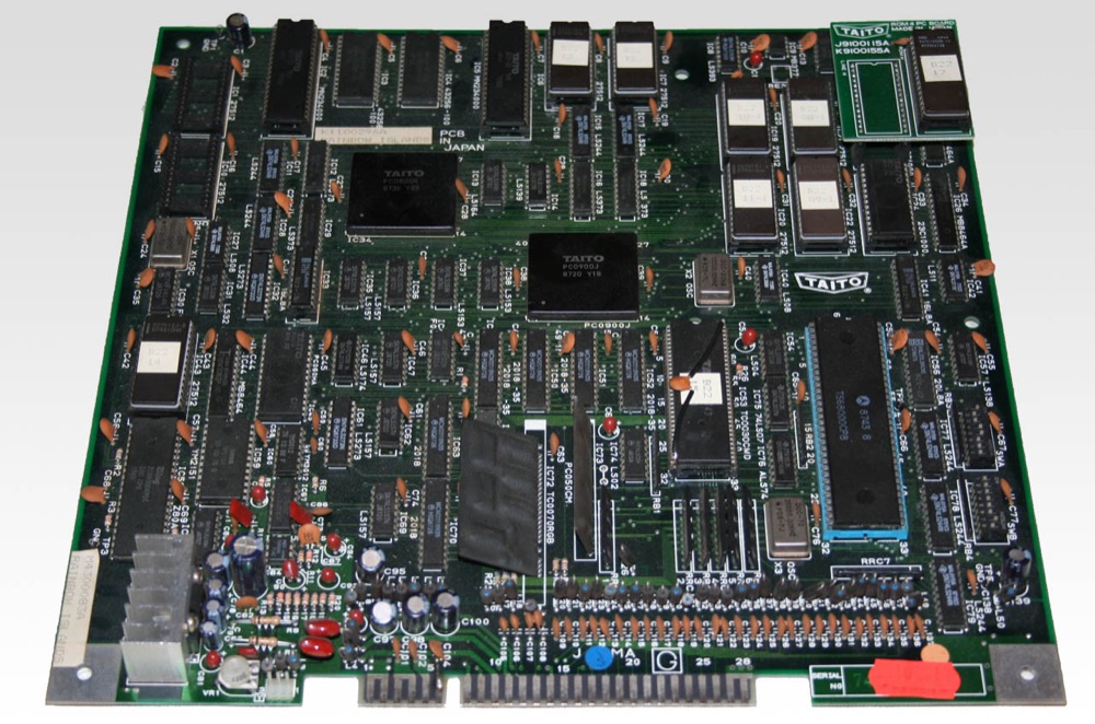
PCB Taito (Rainbow Islands) — photo by Noggin73, domaine public (Wikimedia Commons).
Identification
| Field | Value |
|---|---|
| Manufacturer | Taito |
| Years | 1978 → late 80s |
| CPU | Intel 8080 (Space Invaders) then Z80 (most) |
| Settings | DIP |
The main classic boards
| Hardware | CPU | Games (examples) | MAME driver |
|---|---|---|---|
| Space Invaders (1978) | Intel 8080 @ 2 MHz | Space Invaders (+ variants/clones) | taito/8080bw.cpp |
| Taito SJ (1981-84) | Z80 | Jungle King/Hunt, Elevator Action, Alpine Ski | taito/taitosj.cpp |
| "The Legend of Kage" / early | Z80 | The Legend of Kage, Bubble Bobble, Rastan | taito/bublbobl.cpp, taito/rastan.cpp |
Space Invaders: an 8080 drives a B&W bitmap framebuffer; the "colour" comes from a plastic overlay (green/red strips) glued on the screen — no hardware colour. It's the game that launched the golden age.
Notable games
Space Invaders (1978), Qix (1981), Jungle King (1982), Elevator Action (1983), The Legend of Kage (1985), Bubble Bobble (1986), Rastan (1987), Operation Wolf (1987)…
DIP settings transcribed
Several Taito games have their DIP tables in-wiki (e.g. Bubble Bobble): → DIP reference.
Taito America's Service Tips ✅
A collection of numbered bulletins, and two of them hold for the whole range
The Service Tips collection of Taito America Corporation (1256 Estes Avenue, Elk Grove Village, Illinois) gathers bulletins numbered by year — 81-13, 81-23, 82-17, 83-1… ⓘ Each carries three boxes at its head: MANDATORY, ON FAILURE ONLY, FOR YOUR INFORMATION, one of which is ticked. That is the first thing to read: it says whether the bulletin is an obligation, a conditional repair or plain information.
⚠️ Beware what a bulletin's title does not say. 81-23, headed only "SUBJECT: SELF TEST" without naming a game, in fact describes the self-test of one specific game: its content cites the "LUPIN and COPS" sprites, ROM locations (3D, 3C, 3B, 3A) and display faults located at 12-M, 12-L, 13-M, 13-L, 15-M, 15-L, 1-H. Applied as-is to another Taito, it would mislead.
Bulletin 81-13 — the FMP001 regulator, and this one is cross-range ✅
ⓘ This one explicitly covers "ALL TAITO GAMES WITH A FMP001 SWITCHING REGULATOR", which makes it a platform document rather than a game one.
⚠️ The procedure sets conditions before any measurement: "THIS TROUBLESHOOTING PROCEDURE SHOULD BE DONE IN A NO-LOAD CONDITION WITH THE B-CONNECTOR UNPLUGGED. YOU WILL BE LOOKING FOR SHORT CIRCUITS EXCEPT WHERE NOTED." ⓘ Off-load and with the B connector unplugged — a reading taken otherwise does not compare with this tree.
The tree starts from the fuse symptom and descends to the component:
| Symptom | What the bulletin has you check |
|---|---|
| Primary failure, F1 blown instantly | bridge rectifier, D05 (C2335), D01 (C2812) |
| +12 V failure, F2 blown instantly | D26 (RD18E), C27 (33 µF 25 V) |
| +12 V low or absent | D23 (RD11E) · D10 (RD5.1E) · D4 (RD8.8E) · D2 (C1384) · IC1 (µPC311C) between pins 4 and 8 · D8 (CTU22S) · C7, C8 (1000 µF 25 V) |
| +12 V too high | D2 (C1384) |
| +12 V cannot be adjusted | IC1 (µPC311C) between pins 2 and 3 · R22 (1 kΩ) — "no connection of central terminal or bad soldering" |
| −12 V failure, F3 blown | R26 (RD18E), C28 (33 µF 25 V) |
| −12 V low or absent | D7 (CTU22S) |
| +5 V failure, F5 (6 A) blown | D27 (RD7.6E) |
| +5 V cannot be adjusted | IC2 (µPC311) between pins 2 and 3 · D10 (RD5.1E) |
ⓘ The capacitors are named with their values, so they can be checked without the schematic: 2200 µF 10 V and 100 µF 16 V also appear in the too-high and cannot-adjust branches.
Bulletin 83-1 — the 1982 Service Tips index, and a duplicated number
ⓘ A bulletin that repairs nothing: it says what exists. Taito America published the index of its Service Tips each year, to be ordered "send a self addressed stamped envelope". The 1982 one:
| 82-1 · 82-3 · 82-12 | Qix — 19″ monitor schematic · static freeze · message memory failure |
| 82-5 · 82-6 · 82-7 | Alpine Ski — joystick · "T" connector · troubleshooting chart |
| 82-8 to 82-11, 82-21, 82-23 | Grand Champion — block diagram, power supply schematic, intermittent resets, coin registering, lock-ups, steering wheel |
| 82-13 · 82-14 · 82-15 | Colony 7 — freeze-up · Wild Western — operators manual misprint · coinage switch setting |
| 82-17 | ⚠️ vertical deflection circuit revision — see Wells-Gardner |
| 82-18 · 82-19 | KRAM — no high-score-to-date program · Electric Yo-Yo — number of yo-yos |
| 82-20 · 82-22 | Qix, KRAM, Yo-Yo, Space Dungeon — switch test · coin door processor |
| 82-23 · 82-24 | Alpine Ski, Wild Western, Jungle Hunt — power supply · Jungle Hunt — sound troubleshooting chart |
⚠️ Number 82-23 is assigned twice in the original index — once to "Alpine Ski, Wild Western, Jungle Hunt / Power Supply", once to "Grand Champion / Steering Wheel". ⓘ This wiki reproduces the index as printed; asking for "82-23" was therefore not enough.
ⓘ 82-14 deserves noting for itself: a bulletin whose subject is "Wild Western / Operators Manual Misprint". The manufacturer documented the errors in its own manuals — one more reason not to treat a single manual as a final authority.
The second Service Tips compilation, and what it adds ✅
The wiki had the index. Here are the bulletins.
The compilation already archived runs to 11 pages for 24 bulletin numbers: it is essentially a contents list. A second document of 42 pages carries the bulletins themselves.
⚠️ And it runs later in time: the index stops at 83-1, this one holds 83-2, 83-5, 83-6, 83-7 and 83-13 — ⓘ five 1983 bulletins the index mentions nowhere.
| Bulletin | Subject |
|---|---|
| 83-2 | ⓘ Troubleshooting "S.J." systems |
| 83-5 | Power supply +5 V problems — "improve Q5's connection on power supply" |
| 83-6 | Coin door cable pinched in the frame — harness re-routing |
| 83-7 | +5 V failure — hints for isolating the fault |
| 83-13 | ⓘ Theory of operation of the "S.J." system |
ⓘ Two of the five are about the +5 V, on a platform for which this wiki held no power documentation at all → mains chain.
The Taito SJ, described by its maker ✅
Bulletin 83-13 — ticked FOR YOUR INFORMATION — covers Alpine Ski, Wild Western, Jungle Hunt and Front Line, and describes the "S.J." system that the table at the top of this page summarised only as "Z80":
| Item | What the bulletin writes |
|---|---|
| Processors | two Z-80s: the main (video) at 4 MHz, the sound one at 3 MHz |
| ⚠️ Clocks | ⓘ each CPU has its own clock circuit and its own crystal |
| Video master clock | 12 MHz — ⚠️ "with the exception of the microprocessors" |
| Scratchpad RAM | sound: 2 KB (2114) · main: 2 KB (2016) |
| Program ROM | independent banks, ⓘ jumperable to most common EPROM types |
| CPU-to-CPU | byte-I/O transfers on a latch |
| I/O | memory-mapped throughout; ⓘ the Z-80's ports are used only to clear asserted interrupts at the start of each machine cycle ("M1" state) |
| Background | three completely independent background pages, each movable in any direction |
⚠️ The 12 MHz does not clock the processors. ⓘ Measuring 12 MHz somewhere on an S.J. board therefore tells you nothing about the CPUs — the same misreading as the 19.968 MHz on the MCR, in reverse.
ⓘ And the sound stage is fragile by construction: "the sound processor's address and data lines are unbuffered due to a low component count in the sound circuitry".
⚠️ The scan carries a third-party watermark, visible diagonally across the pages. This wiki says so rather than pretending it is not there.
Archived Taito game manuals ✅
ⓘ This wiki does not open a page per game. These manuals are archived and listed here for what they are — operating, maintenance and parts documents, often the only sourced figures for a given cabinet.
30 manuals and catalogues, by title
- Alpine Ski
- Bazooka [ARCADE] 1977
- Change Lanes
- Crazy Balloon
- Crazy Climber
- Crazy Climber Upright
- Cup Finals
- Elevator Action
- Exerion
- Field Goal
- Grand Champion
- Grand Champion — Pinouts
- Kiki KaiKai
- Kram
- Kyuukyoku Tiger II
- Lock 'N Chase
- NBA Jam Manual Version
- Pinout Diagram: Kick and Run
- Pit & Run
- Polaris
- Power Goal Instruction Manual
- Qix
- Space Chaser
- Space Dungeon
- Speed Race — Manual SP070029
- Top Landing
- Zarzon
- Zookeeper
- Zookeeper: Upright Operation, Maintenance and Service Manual from
⚠️ Titles come from the title pages where legible, otherwise from Internet Archive's catalogue. ⓘ Three of them are not game manuals and are handled elsewhere: the G.T.C. 100, the Trimline and the Space Invaders Cocktail parts catalogue → Taito cabinets.
Common faults
| Symptom | Likely cause | Lead |
|---|---|---|
| Corrupt bitmap image (SI) | video RAM / 8080 | RAM test, contacts |
| Wrong colours (SI) | misplaced overlay | Reposition the overlay |
| Corrupt sprites/tiles | video RAM, customs | RAM test |
| No sound | amp / PSG / SN76489 | Sound-stage diagnosis |
| No image | Power, CPU, harness | Base diagnosis |
Old boards → discrete TTL logic, recap + re-soldering; many period Space Invaders bootlegs (identification).
Modernisation & mods
The common ground for every JAMMA board
Video, power, control panel and upscalers depend on the cabinet rather than the board: everything is centralised in Modernising a cabinet. To run the board outside a cabinet (at home, on a display): supergun.
- Storage 🟡: the game lives in EPROM/mask ROM on the board. Changing or restoring a game means reprogramming the EPROMs (and, for a mask ROM, using a pinout adapter) → EPROM method.
- Media preservation: replacing the original storage, multicarts, ODEs and modern options by family → PCB preservation hub.
- Scan rate 📺: ~15.62 kHz / 59.2 Hz — standard resolution, a classic 15 kHz chassis is fine → tri-sync and upscalers.
(Computed from the MAME sources —
taito/bublbobl.cpp— pixel clock ÷ htotal.) - FPGA / emulation: see the Emulation & FPGA section below.
Repair (technician)
- 8080/Z80 logic (80s): diagnose TTL / RAM / buffers, good/bad comparison. Space Invaders = 8080 + analog/SN76477 sound (a dedicated stage).
- Sound: amp + SN76489/PSG — diagnose separately.
- 2716/2732 EPROMs on sockets: oxidised legs → re-tin / turned-pin socket.
- Edge contacts: clean; check the PSU (few electrolytics).
→ Methods: PCB fault-finding · Recap · EPROM · Traces & vias
Expected clocks — measurement table ✅
Values extracted from the MAME sources for this platform. On a scope or frequency counter, a clock that is missing or off-value points straight at the crystal, the divider or the chip at fault — the fastest starting point on a dead board.
| Component | Expected clock | Role |
|---|---|---|
| YM2203 | 3 MHz | FM (sound) |
| Z80 | 3 MHz · 6 MHz | sound CPU (usually) |
How to read this table
Several values for one component = several board variants in this family (or several instances of the chip clocked differently). These frequencies are those of the clock signal at the component's input, not of its original crystal — on many boards the clock is divided down from a single master crystal.
Archived original schematics ✅
Manufacturer schematics for games in this family, archived locally (so they do not depend on a third-party site staying up). They give the board's real functional breakdown: clock tree, address decoding, video stage, sound stage, power supply — exactly what you need to trace a missing signal back to its source.
-
Operation Wolf — full schematic (PDF)
-
Gladiator — full schematic (PDF)
- Polaris — full schematic (PDF)
- Space Invaders (manual + schematics) — full schematic (PDF)
Scope and limits
A schematic applies to the game and revision named. Within one family the general breakdown (buses, decoding, sound/video stages) carries over from board to board, but component references and custom chip pinouts do not transpose between titles. Use it as a map of the logic, not as a cross-reference table.
Source: the Arcade Game Manuals collection on the Internet Archive. Manufacturer documents with no explicit licence, kept here for preservation (machines out of service for over 25 years).
Original manuals for games on this platform ✅
Manufacturer manuals for games running on this board. Beyond the instructions, they very often carry the full DIP settings, the connector pinout, the test procedure, the parts list and the expected voltages.
- Operation Wolf — original manual (PDF)
Space Invaders — one Taito manual and three schematic sheets
All of them carried the same label here. Opened and identified from their title page on 13 August 2026.
| Doc | What the cover carries | Pages |
|---|---|---|
| TV070014 | Space Invaders — Service Instructions and Parts Catalog, Taito Corporation. The cover shows the table cabinet | 29 |
| M051-00739-A005 | Single sheet — Game Logic board schematic, revision A | 1 |
| M051-00739-B005 | The same board, revision B | 1 |
| M051-0075-A005 | Game Logic board of the cocktail cabinet — a different drawing number | 1 |
⚠️ Three sheets, three drawing numbers. Read the one silkscreened on the board before following a schematic: A005 and B005 are not the same revision.
→ Full catalogue: service manuals, wiring & game manuals
DIP settings ✅
8 games on this platform, settings extracted from the MAME sources (INPUT_PORTS_START blocks). The Position column gives the switch's physical reference on the board (SW2:!3,!4 = bank SW2, levers 3 and 4) — which is what lets you set it up without the paper manual. Games are sorted by MAME set name.
DIP settings — MAME set boblbobl
| Setting | Position | Options (default in bold) |
|---|---|---|
| Mode | — | Game, English · Game, Japanese · Test (Grid and Inputs) · Test (RAM and Sound) |
| Flip Screen | — | Off · On |
| Demo Sounds | — | Off · On |
| Coin A | — | 2C 1C · 1C 1C · 2C 3C · 1C 2C |
| Coin B | — | 2C 1C · 1C 1C · 2C 3C · 1C 2C |
| Difficulty | — | Easy · Normal · Hard · Very Hard |
| Bonus Life | — | 20K 80K 300K · 30K 100K 400K · 40K 200K 500K · 50K 250K 500K |
| Lives | — | 1 · 2 · 3 · 5 |
| Monster Speed | — | Normal · Medium · High · Very High |
DIP settings — MAME set boblcave
| Setting | Position | Options (default in bold) |
|---|---|---|
| ROM Type | DSW-B:8 | IC52=512kb, IC53=none · IC52=256kb, IC53=256kb |
DIP settings — MAME set bublbobl
| Setting | Position | Options (default in bold) |
|---|---|---|
| Mode | DSW-A:1,3 | Game, English · Game, Japanese · Test (Grid and Inputs) · Test (RAM and Sound)/Pause |
| Flip Screen | DSW-A:2 | Off · On |
| Demo Sounds | DSW-A:4 | Off · On |
| Coin A | DSW-A:5,6 | 2C 1C · 1C 1C · 2C 3C · 1C 2C |
| Coin B | DSW-A:7,8 | 2C 1C · 1C 1C · 2C 3C · 1C 2C |
| Difficulty | DSW-B:1,2 | Easy · Normal · Hard · Very Hard |
| Bonus Life | DSW-B:3,4 | 20K 80K 300K · 30K 100K 400K · 40K 200K 500K · 50K 250K 500K |
| Lives | DSW-B:5,6 | 1 · 2 · 3 · 5 |
| ROM Type | DSW-B:8 | IC52=512kb, IC53=none · IC52=256kb, IC53=256kb |
DIP settings — MAME set bublboblp
| Setting | Position | Options (default in bold) |
|---|---|---|
| Language | SW A:1 | English · Japanese |
| Flip Screen | SW A:2 | Off · On |
| Demo Sounds | SW A:4 | Off · On |
| Coin A | SW A:5,6 | 2C 3C · 1C 1C · 2C 1C · 1C 2C |
| Coin B | SW A:7,8 | 2C 3C · 1C 1C · 2C 1C · 1C 2C |
| Difficulty | DSW-B:1,2 | Easy · Normal · Hard · Very Hard |
| Bonus Life | DSW-B:3,4 | 20K 80K 300K · 30K 100K 400K · 40K 200K 500K · 50K 250K 500K |
| Lives | DSW-B:5,6 | 1 · 2 · 3 · 5 |
| Edit Mode | DSW-B:7 | Off · On |
DIP settings — MAME set dland
| Setting | Position | Options (default in bold) |
|---|---|---|
| Game | — | Dream Land · Super Dream Land |
| Lives | — | 1 · 2 · 3 · 100 (Cheat) |
DIP settings — MAME set sboblboblb
| Setting | Position | Options (default in bold) |
|---|---|---|
| Game | — | Bobble Bobble · Super Bobble Bobble |
| Lives | — | 1 · 2 · 3 · 100 (Cheat) |
DIP settings — MAME set tokio_base
| Setting | Position | Options (default in bold) |
|---|---|---|
| Cabinet | SW A:1 | Upright · Cocktail |
| Flip Screen | SW A:2 | Off · On |
| Demo Sounds | SW A:4 | Off · On |
| Coin A | SW A:5,6 | 2C 1C · 1C 1C · 2C 3C · 1C 2C |
| Coin B | SW A:7,8 | 2C 1C · 1C 1C · 2C 3C · 1C 2C |
| Enemies | SW B:1 | Few (Easy) · Many (Hard) |
| Enemy Shots | SW B:2 | Few (Easy) · Many (Hard) |
| Bonus Life | SW B:3,4 | 100K 400K · 200K 400K · 300K 400K · 400K 400K |
| Lives | SW B:5,6 | 3 · 4 · 5 · 6 |
| Language | SW B:8 | English · Japanese |
DIP settings — MAME set tokiob
| Setting | Position | Options (default in bold) |
|---|---|---|
| Lives | SW B:5,6 | 3 · 4 · 5 · 99 (Cheat) |
Check against your own board
These settings apply to the game and revision described by MAME. One title may have several DIP sets depending on region or revision, and some systems use soft-dips (settings in memory, via the test menu) rather than physical switches. In case of a discrepancy, the board's silkscreen and the test menu are authoritative.
See also: DIP reference · game manuals
Procedure — a dead board, step by step ✅
What this adds
The general method lives in PCB diagnosis. This is its application to this platform: the same order, but with the values actually expected here, so you do not have to go back and forth.
Tools: multimeter, oscilloscope (or frequency counter), current-limited bench supply, desoldering braid. → Tooling
If the board is still in a cabinet
A CRT holds its charge with the machine unplugged. → CRT safety
1. Inspection, power off. Corrosion, cut tracks, oxidised EPROM legs, leaking SMD capacitors, dubious earlier repairs.
2. The connector, before anything else. A large share of "dead boards" are a contact problem, not a fault. Clean the contacts with isopropyl alcohol and reseat — not with an abrasive eraser on a gold edge, which takes the plating off and brings the problem back worse. It costs two minutes and settles the question.
3. Power, measured on the board. Aim for +5.0 V measured as close as possible to where power reaches the board — not at the PSU output: the drop is in the loom, and that is exactly what makes a board boot on the bench and not in the cabinet. Where you probe depends on this board's connector — JAMMA edge, JVS loom or a proprietary harness — plenty of makers kept one long after JAMMA arrived — see Identification above. → Wiring Check −5 V and +12 V too if the sound stage uses them. Suspected short: bring it up current-limited and find the hot spot.
4. /RESET. It must release after power-up. Held low = the CPU never starts. A 1–2 Hz loop is not the reset circuit, it is the watchdog: the CPU is crashing at boot, so look at the bus, not at the reset.
5. Clocks — the values expected on this platform.
- YM2203 → 3 MHz (FM (sound))
- Z80 → 3 MHz · 6 MHz (Sound CPU (usually))
Several values for one component means several board variants in this family, not several readings on the same one: identify yours before calling a clock wrong. That is the mistake that replaces a healthy crystal.
6. Bus. Activity on the main CPU's address lines tells you whether it is running or frozen. Frozen with good clocks and good reset → work RAM, bus buffers, ROMs.
7. It boots but the picture or the sound is wrong — that is another job: see Common faults on this page, then signal tracing.
Emulation & FPGA
- Emulation: MAME (
8080bw.cpp,taitosj.cpp,bublbobl.cpp,rastan.cpp…). - FPGA / MiSTer: cores available (Space Invaders, Bubble Bobble, Rastan, Elevator Action…).
EPROM repair
8080 program (Space Invaders, 1978) in small 2708 / 2716 EPROMs (1-2 KB), + the famous cellophane colour overlay. Period components (±5/±12). Many variants/licences (Midway).
Lineage
Precedes the Taito 16-bit systems (B/F1/F2/F3) on the 68000.
Photos / assets
(To add: Space Invaders board, colour overlay, Bubble Bobble board.)
Sources & attribution
-
Photo PCB Taito (Rainbow Islands) — Noggin73, domaine public, Wikimedia Commons — https://commons.wikimedia.org/wiki/File:Rainbow_Islands_PCB.jpg
-
MAME —
taito/8080bw.cpp,taitosj.cpp,bublbobl.cpp,rastan.cpp(8080/Z80, games) — https://github.com/mamedev/mame - Wikipedia — Space Invaders / Taito — CC-BY-SA — https://en.wikipedia.org/wiki/Space_Invaders

Review & corrections
How this space is used
Spotted a wrong value, an outdated procedure, a chip reference that does not match your board? Say so here, with what you observed (model, board revision, serial number, measurement). Every report is cross-checked against a source before anything changes — an unverifiable correction is published as “reported by …, not cross-checked” rather than silently applied.
Reading is open to everyone; posting requires signing in with Discord. Reports from the wiki's declared reviewers are handled first; anyone else's are read too, but go through a human before anything is changed.