Namco Dragon Ball ZENKAI Battle Royale cabinet (the "Blanc")¶
Bandai Namco sitdown cabinet, 2011, built for Dragon Ball ZENKAI Battle Royale. Collectors call it the "Namco Blanc", by symmetry with the Noir and the Grigio.
The \"Blanc Cabinet\" name
The cabinet is known as the Blanc Cabinet. Its operation manual, for its part, is printed under the game's title and does not use that name. Hard*Candy lists it as "Blanc Cabinet", with no technical data filled in, and Arcade Otaku has no page.
The figures below therefore come from the manual itself, the only primary source available.
Identification¶
| Field | Value |
|---|---|
| Manufacturer | Bandai Namco Games |
| Year | 2011 |
| Original game | ドラゴンボール ZENKAI バトルロイヤル (Dragon Ball ZENKAI Battle Royale) |
| Type | Sitdown |
| Screen | 32″ LCD, 1920 × 1080, analogue / digital (HDCP) input |
| Orientation | horizontal only (横向き専用) |
| Dimensions | 890 × 800 × 2200 mm (W×D×H) — 設置時, sign board included |
| Dimensions, cabinet only | 870 × 800 × 1480 mm (W×D×H, 分割時 — キャビネット Assy) |
| Weight | 150 kg installed (rack Assy included) — breakdown below |
| Mains | AC 100 V ±10 V (50/60 Hz) |
| Consumption | 220 W without game board · 330 W with |
| Max current | 2.7 A without game board · 4.0 A with |
| Cashbox | ~¥300,000 (3,000 × ¥100 coins) |
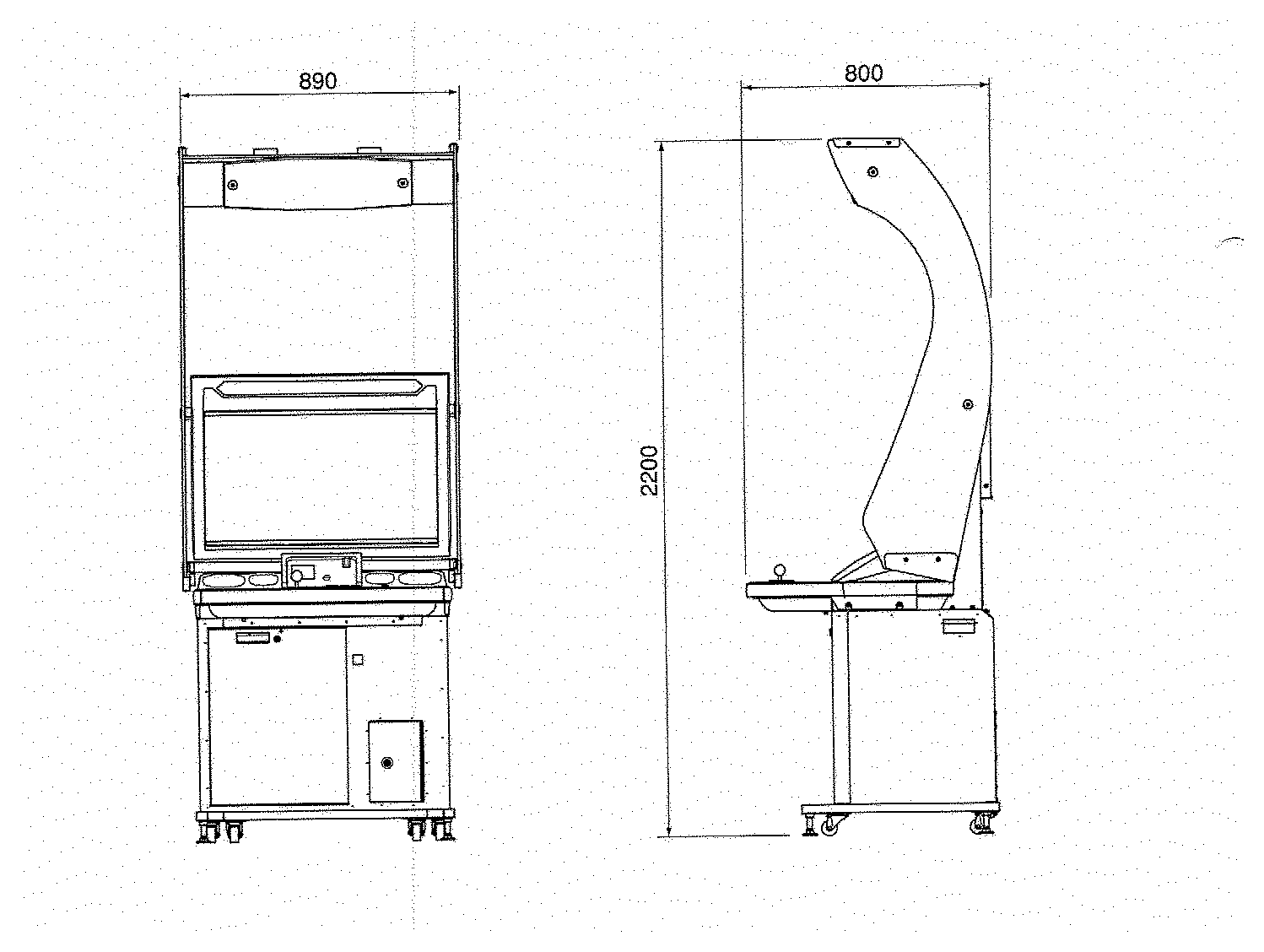
⚠️ The 2200 mm includes the sign board
The manual distinguishes two states, §2 仕様, folios 10-11:
- ①設置時 (installed): 横幅 (W) 890 × 奥行 (D) 800 × 高さ (H) 2,200, with the sign board (サインボード Assy) fitted;
- ②分割時 (split): キャビネット Assy 870 × 800 × 1,480, plus サイドパネル L/R 1410 × 550 × 40, サインボックス 870 × 180 × 180, サインボードピラー L/R 40 × 380 × 1140, サインシート 860 (w) × 820 (h) at 0.5 mm thick (厚さ t — a thickness, not a depth).
The footprint comparison used to draw it with its sign board, alone of its kind beside cabinets measured bare; it now uses the cabinet's 1,480 mm.
Weight, by sub-assembly
§2 仕様 (7) 重量, folio 11 (p. 13 of the PDF):
| Item | Mass |
|---|---|
| ①設置時 (rack Assy included) | 150 kg |
| ②分割時 — キャビネット Assy | 135 kg (rack Assy included) · 125 kg without |
| サイドパネル (L)/(R) Assy | 4 kg each |
| サインボックス | 6 kg |
| サインボードピラー (L)/(R) | 2 kg each |
This page long stated the weight was "absent from the manual". It was there.
This is not a Noir
890 mm wide against 800 for the Noir: a distinct cabinet, not a colour variant.
⚠️ Comparing the 2,200 mm to the Noir's 1,700 mm, however, mixes two measurements: the 2200 is sign board included, the 1700 is a bare cabinet. On comparable terms the Zenkai is 1,480 mm — lower than the Noir.
Two versions¶
| v1 | v2 | |
|---|---|---|
| Neon | purple | orange |
That is the quickest tell, the lighting being visible whether the cabinet is on or off.
⚡ Wiring & power¶
| Aspect | Value |
|---|---|
| Game system | System 357 (S357C-10J board) — Namco's PS3 platform |
| Mains | AC 100 V ±10 V, through a 1 kVA isolation transformer |
| Protection | 250 V 10 A circuit protector + mains filter |
| Internal rails | +24 V, +12 V, −12 V, separate 12 V and 24 V grounds |
| Cooling | DC 12 V fan (connector J6) |
| Network | ALL.Net, up to 4 cabinets per router |
Isolation transformer and input voltage
The manual states that the 100 V input must be matched to the country of operation — hence the 1 kVA isolation transformer. On 230 V European mains, changing the plug is not enough: without adaptation, everything downstream goes up in smoke.
Default wire gauges¶
The wiring diagram gives the gauges to use where none is marked on the wire — rare in a manual, and valuable when rebuilding a loom:
| Circuit | Gauge |
|---|---|
| Monitor | AWG16 |
| Other power circuits | AWG18 |
| Signal lines | AWG24 |
Connector convention: shaded connectors on the diagram are New Universal MATE-N-LOK. Cap connectors take pin contacts, plug connectors take socket contacts.
The two regulators¶
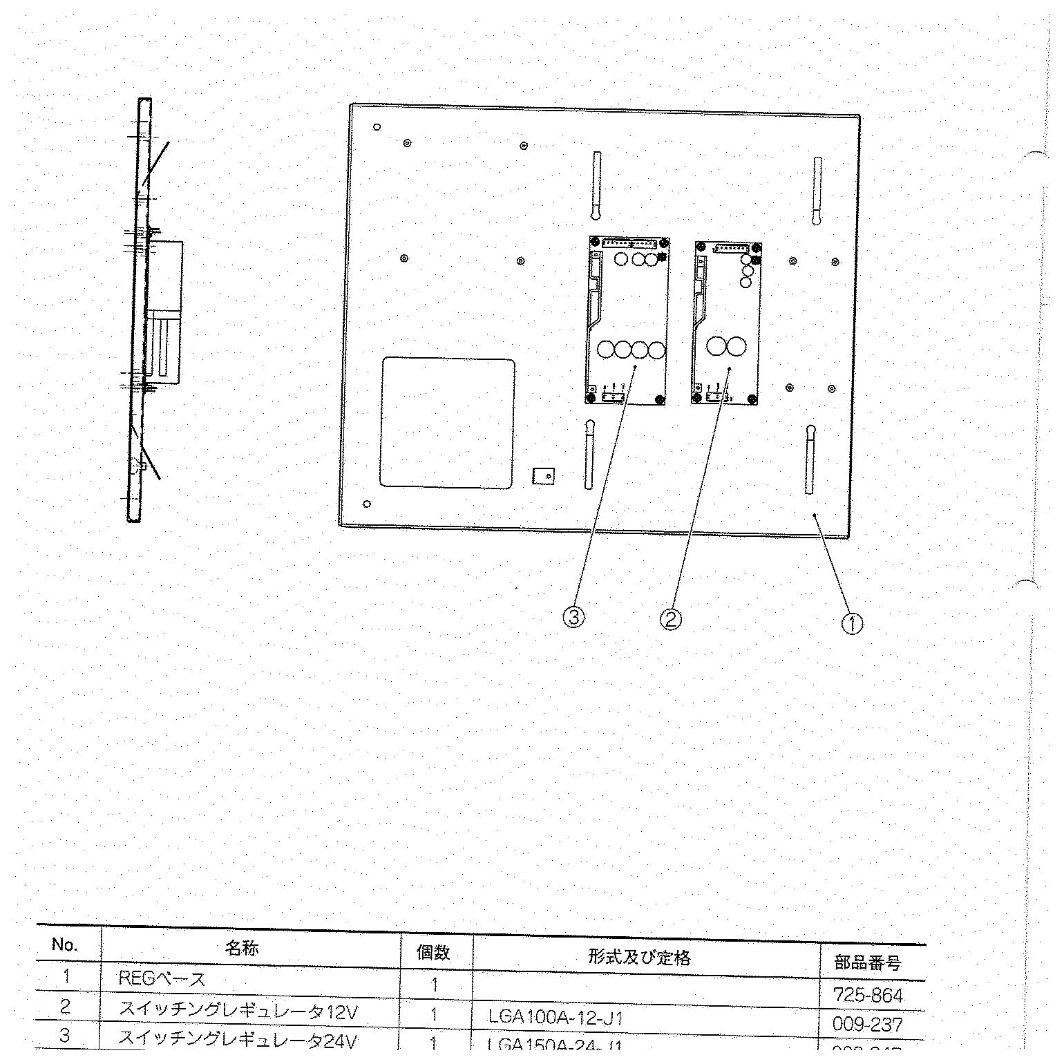
The parts list (section 10-10) finally gives the exact references that the wiring diagram would not let us read:
| Ref. | Item | Manufacturer part | Namco part |
|---|---|---|---|
| 1 | Mounting plate (REG base) | — | 725-864 |
| 2 | 12 V switching regulator | LGA100A-12-J1 | 009-237 |
| 3 | 24 V switching regulator | LGA150A-24-J1 | 009-247 |
Reading the wattage from the part number
These are Cosel LGA series, whose part number carries the rating: LGA100A = 100 W, LGA150A = 150 W. Current follows from the voltage — but check it against Cosel's datasheet rather than that calculation: it is a naming convention, not a figure taken from the manual.
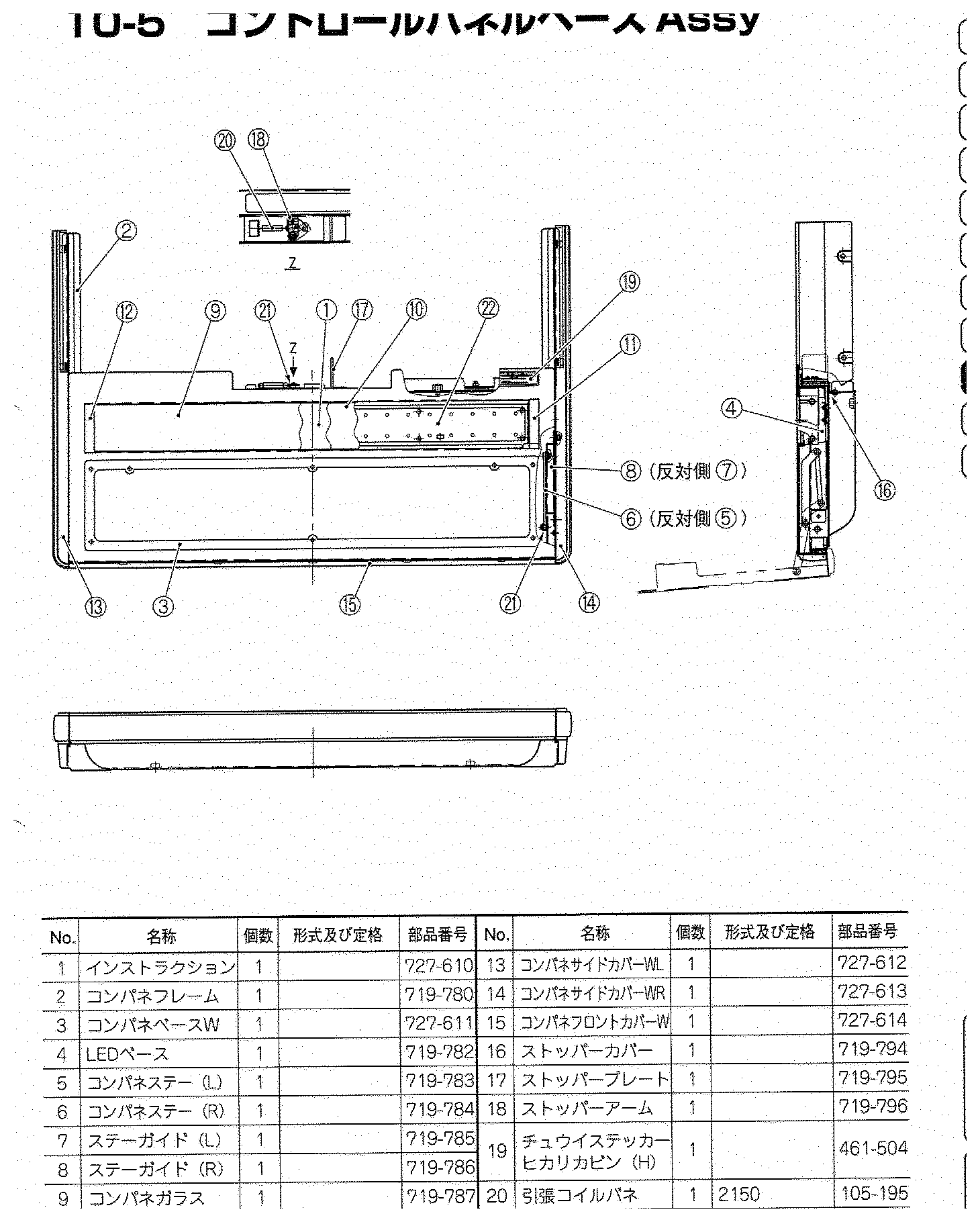
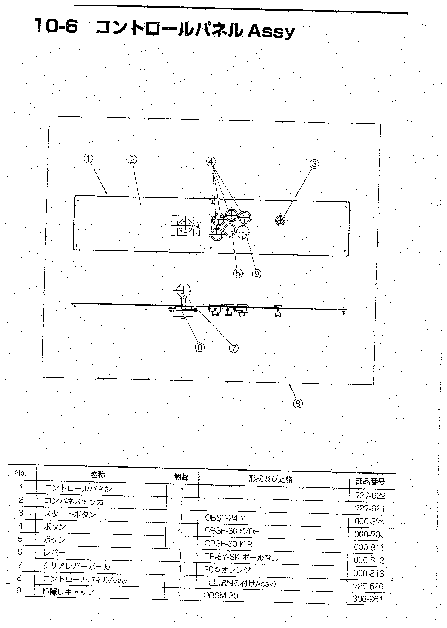
Control panel exploded view¶
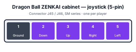
Control panel — pinout¶
Two connectors per player: one for the joystick, one for the buttons.
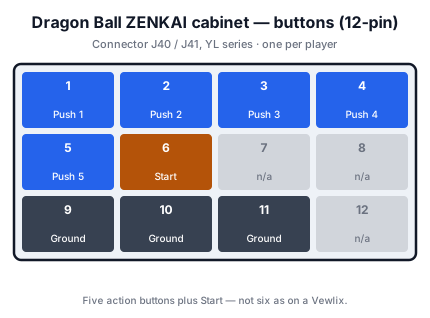
Five buttons, not six
The panel carries five action buttons plus Start per player. That is fewer than a Vewlix or a Noir: the original game is a 3D arena fighter, not a 2D versus game. A six-button panel therefore does not plug straight in.
Other pinouts recorded¶
Monitor OSD board (6-pin) — the screen settings are wired, not in an on-screen menu:
| Pin | Signal |
|---|---|
| 1 | Ground |
| 2 | SERVICE |
| 3 | TEST |
| 4 | VOL 3 |
| 5 | VOL 2 |
| 6 | VOL 1 |
BanaPassport card reader — CARD IF PCB, 7-pin, on shielded cable, with
a read/write module on a ribbon:
| Pin | Signal |
|---|---|
| 1 | +12 V |
| 2 | Ground |
| 3 | P1 TXD |
| 4 | P1 RXD |
| 5 | P1 CTS |
| 6 | P1 RTS |
| 7 | Ground |
That is a full serial link with flow control — not a passive reader.
RS-232 link (connector J11): RXD on 1, TXD on 3, CTS on 5, RTS on 7, ground on 9; the remaining pins are not connected.
Audio — C2-IS-N amplifier board, connector J151 / J152 (5-pin): 1 left speaker +, 2 left −, 4 right +, 5 right −. Main speakers 8 Ω, separate tweeters.
Networking (ALL.Net)¶
The overall connection diagram shows the topology Namco intended:
- a router whose port 0 goes to the ALL.Net router;
- its ports 1 to 4 feed up to four cabinets, on straight LAN cable;
- each cabinet: Ethernet → S357-10J board;
- one cabinet only carries the USB hub with the 4 GB USB key and the card reader — and that one must be set to [No.1] in test mode. Numbers 2 to 4 are free.
Cabinet No. 1 is not interchangeable
Move the USB key to another cabinet without changing the station number in test mode and the group will not form. It is the classic trap of a multi-cabinet install.
Internal assemblies¶
- 🎮 S357C-10J — System 357 board.
- 💾 Hard disk and service PC board.
- 🔊 C2-IS-N amplifier.
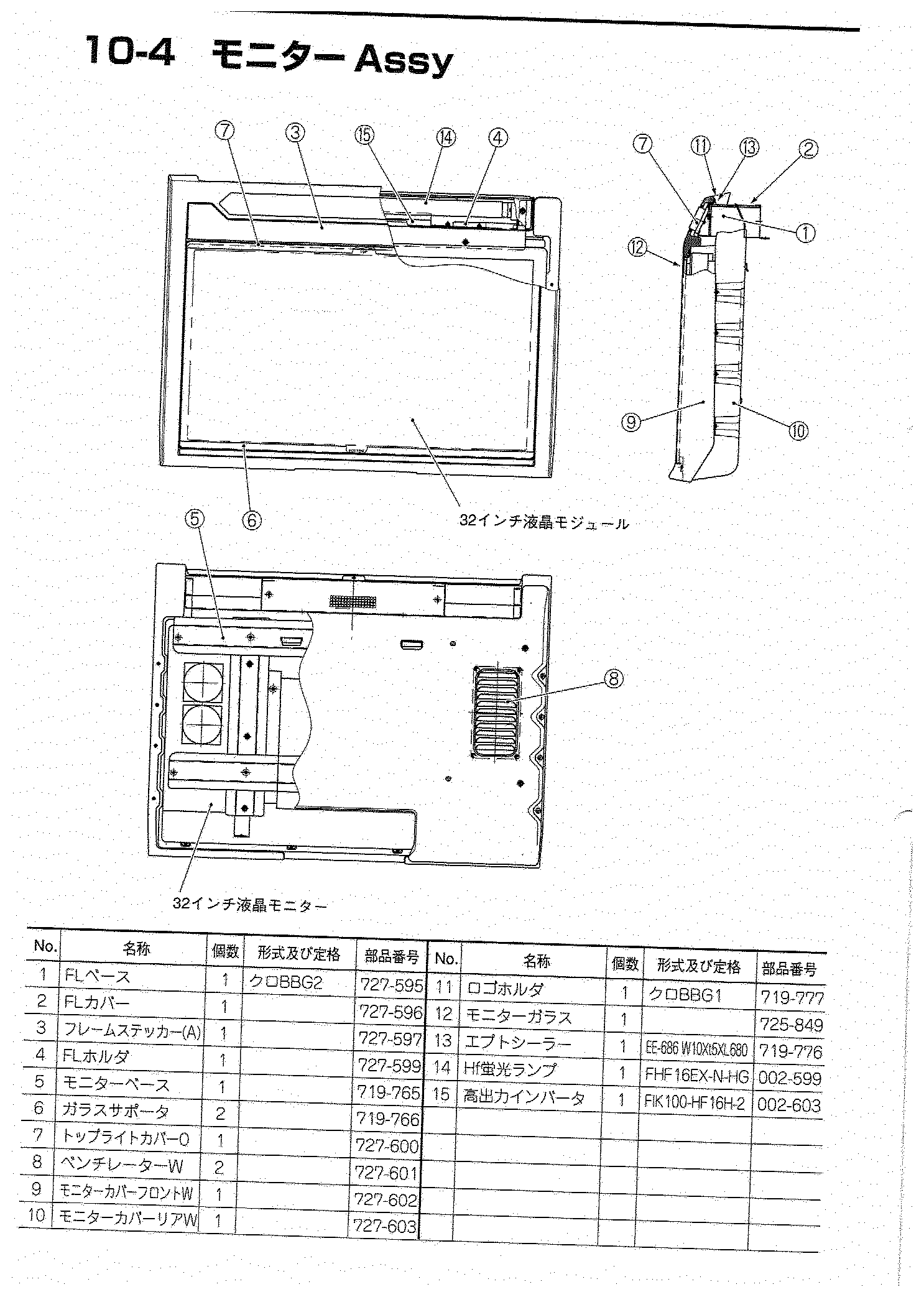
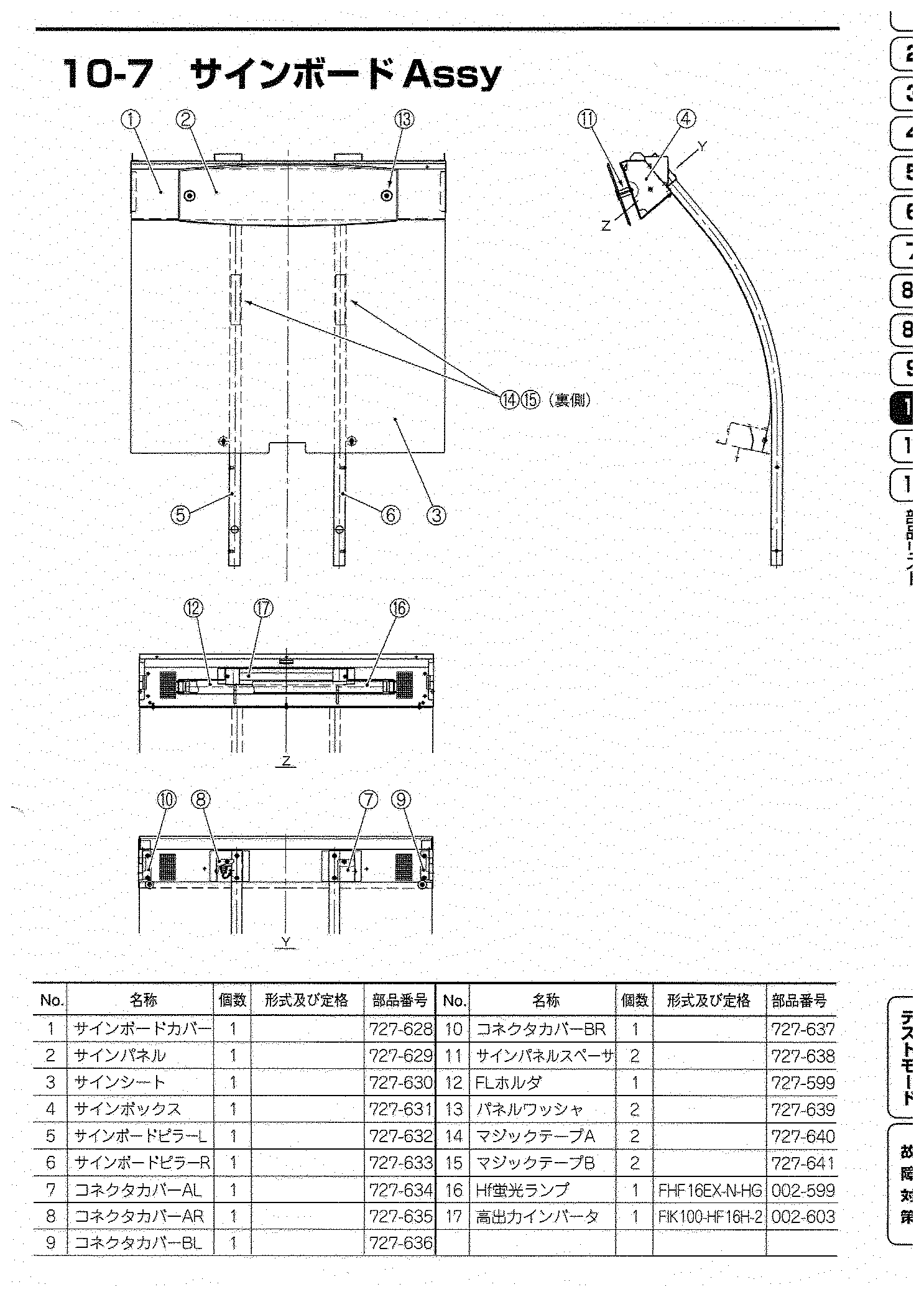
- 💡 Sign board and screen light strip: 16 W Hf fluorescent lamp
(
FHF16EX-N-HG) and high-frequency inverter (FIK100-HF16H-2) — not a cold-cathode tube, contrary to what reading the diagram suggested. See the parts list. - 💳 BanaPassport reader.
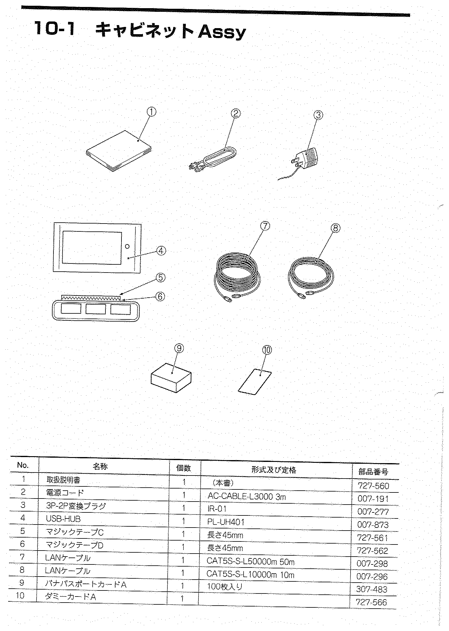
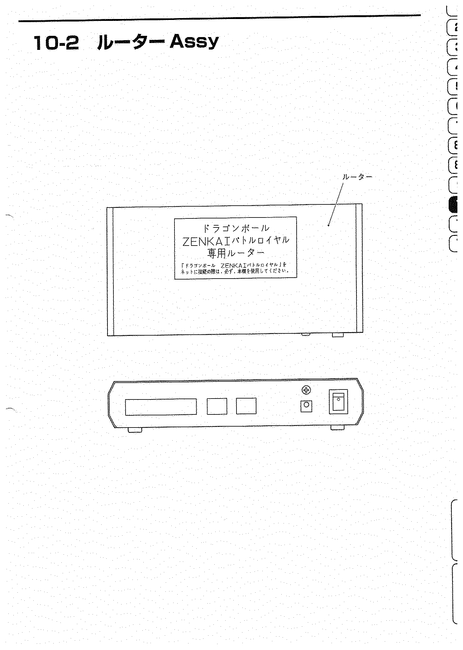
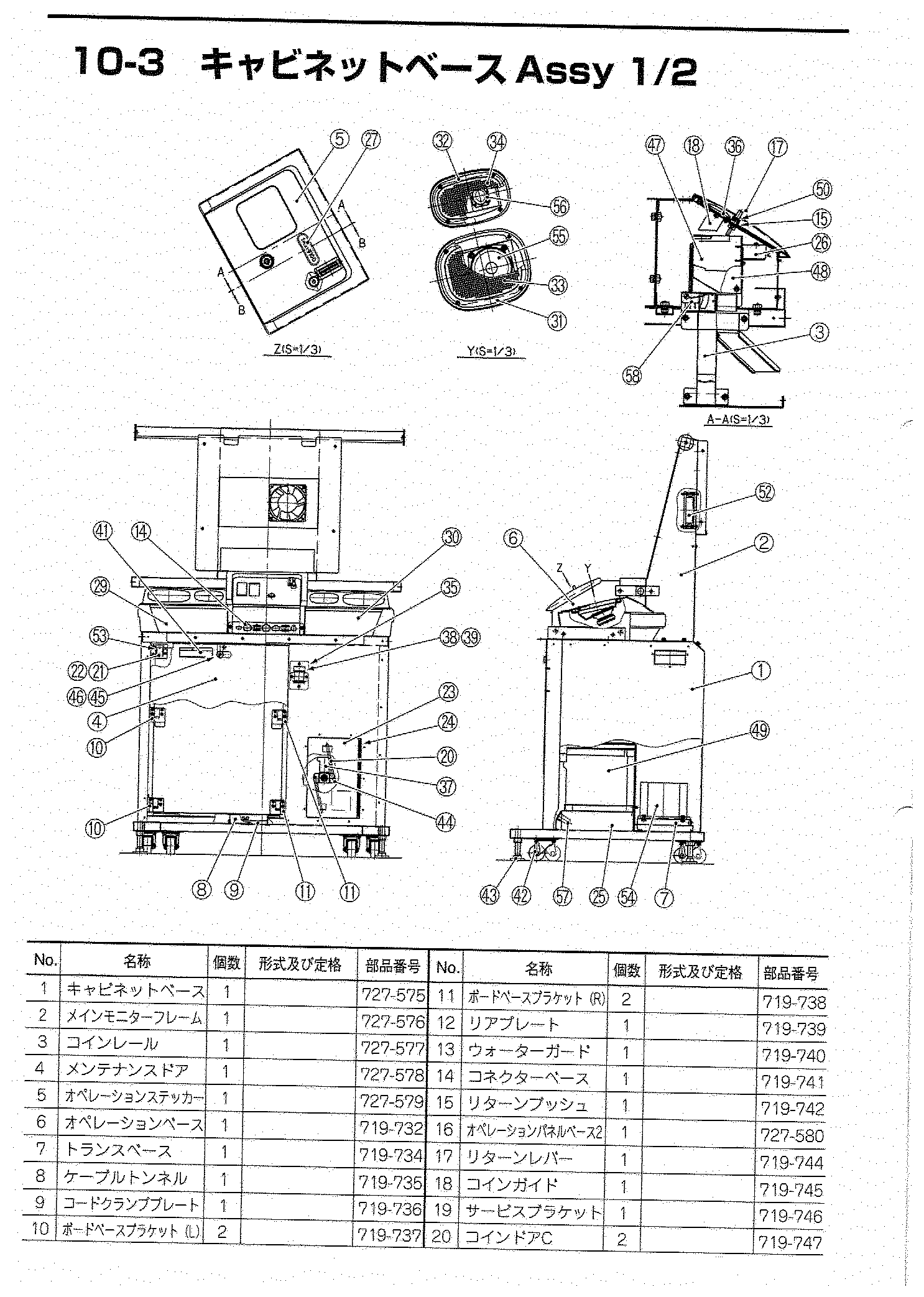
Parts list — the twelve sub-assemblies¶
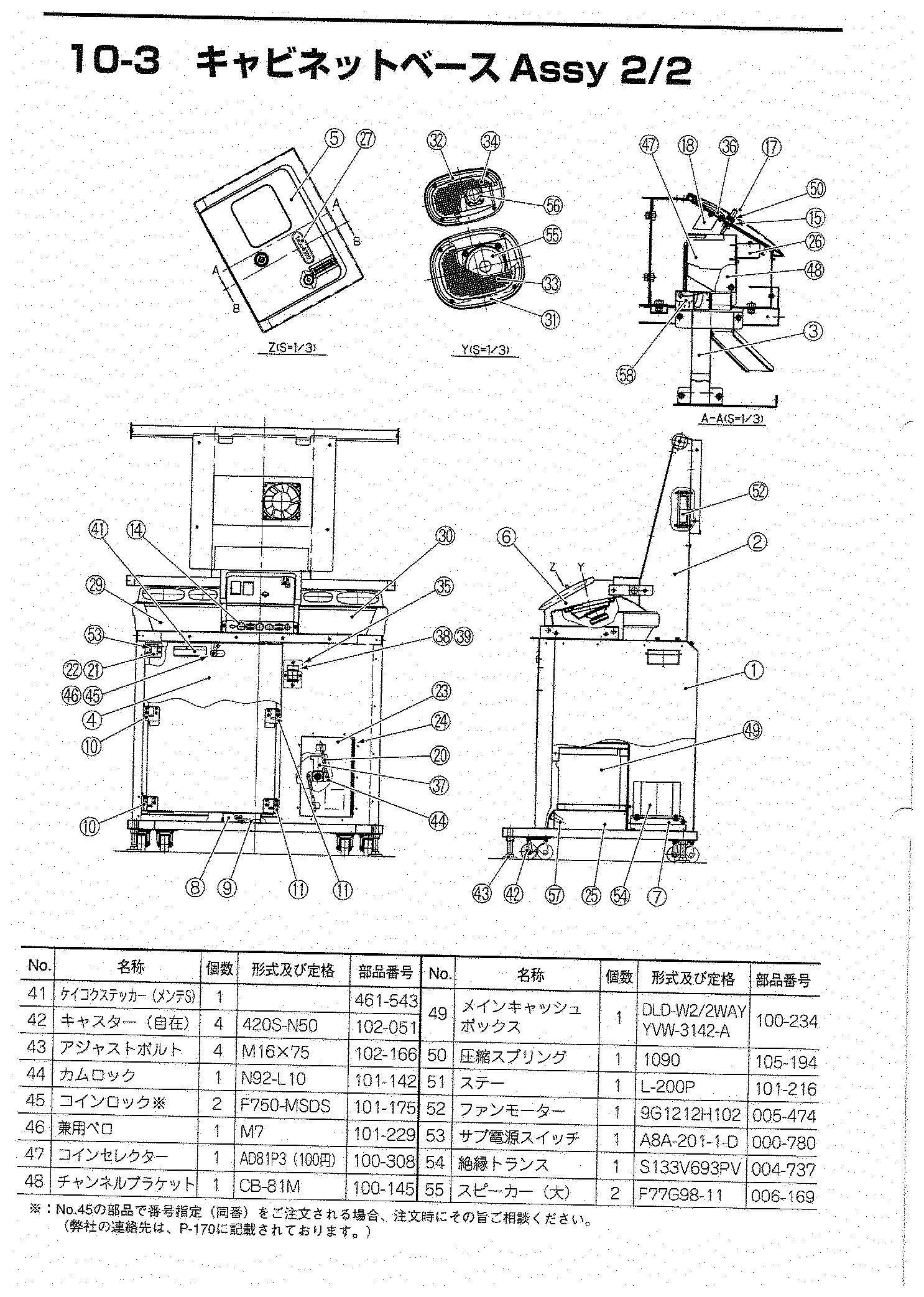
The manual ends with an illustrated parts list: twelve exploded views, each with its numbered parts and their Namco references. That is what lets you order the exact part rather than hunt for an equivalent.
Wear parts — the references that actually matter¶
| Part | Type | Namco ref. |
|---|---|---|
| Hf fluorescent lamp (sign board and screen top light) | FHF16EX-N-HG | 002-599 |
| High-output inverter (same) | FIK100-HF16H-2 | 002-603 |
| 12 V switching regulator | LGA100A-12-J1 | 009-237 |
| 24 V switching regulator | LGA150A-24-J1 | 009-247 |
| Fan | 9G1212H102 | 005-474 |
| Isolation transformer | S133V693PV | 004-737 |
| Coin selector (¥100) | AD81P3 | 100-308 |
| Speaker (large) ×2 | F77G98-11 | 006-169 |
| Swivel casters ×4 | 420S-N50 | 102-051 |
| Levelling bolts ×4 | M16 × 75 | 102-166 |
| Cam lock | N92-L10 | 101-142 |
| Coin locks ×2 | F750-MSDS | 101-175 |
| Sub power switch | A8A-201-1-D | 000-780 |
| Main cash box | DLD-W2/2WAY YVW-3142-A | 100-234 |
The lighting is NOT cold-cathode
The sign board and the strip above the screen use a 16 W Hf fluorescent
lamp (FHF16EX-N-HG) driven by a high-frequency inverter
(FIK100-HF16H-2) — not a CCFL tube.
The distinction matters when ordering: an Hf tube and a CCFL are neither the same family nor interchangeable, and the inverter is specific. Both locations use the same reference, so one part covers them.
The twelve plates¶
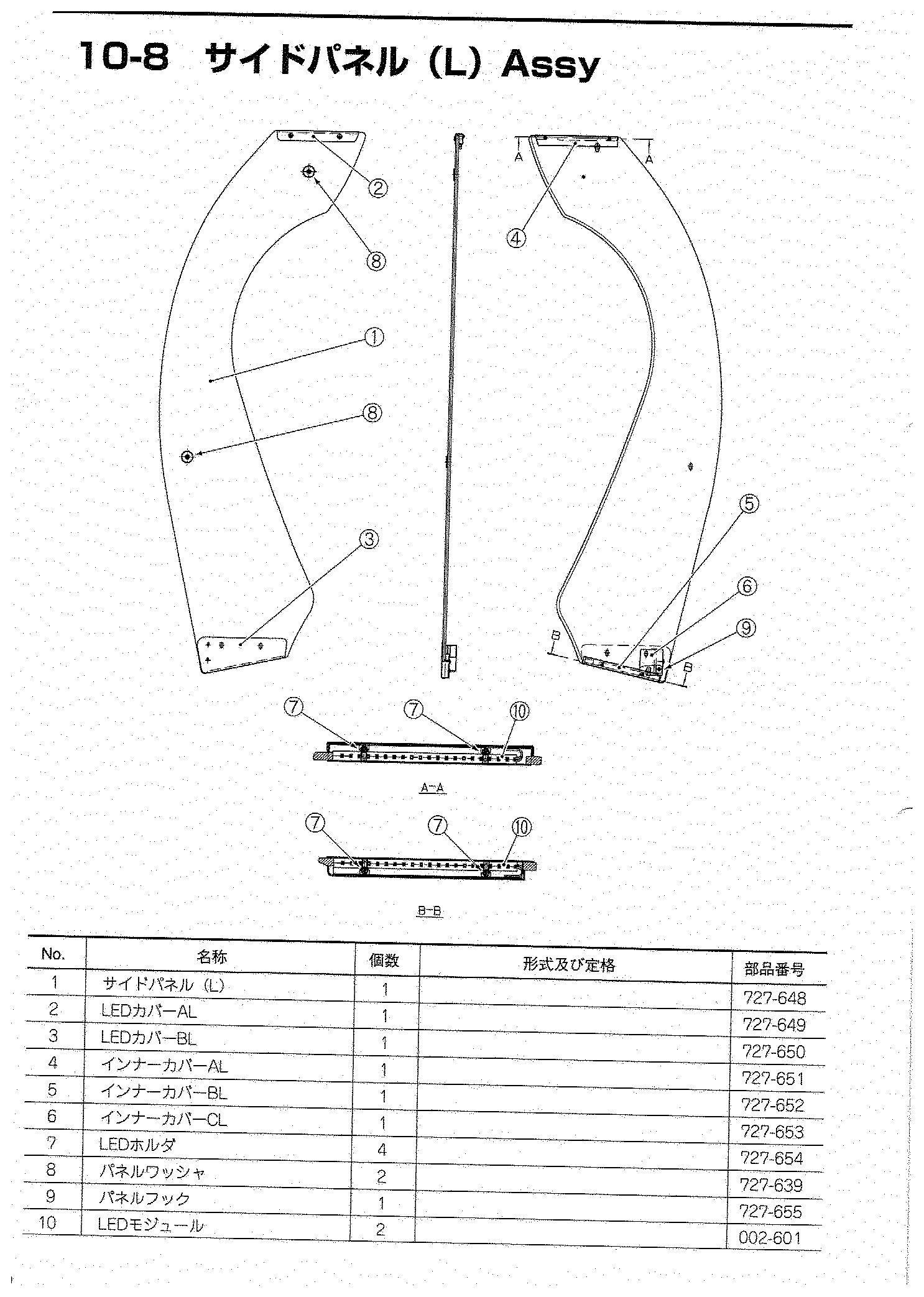
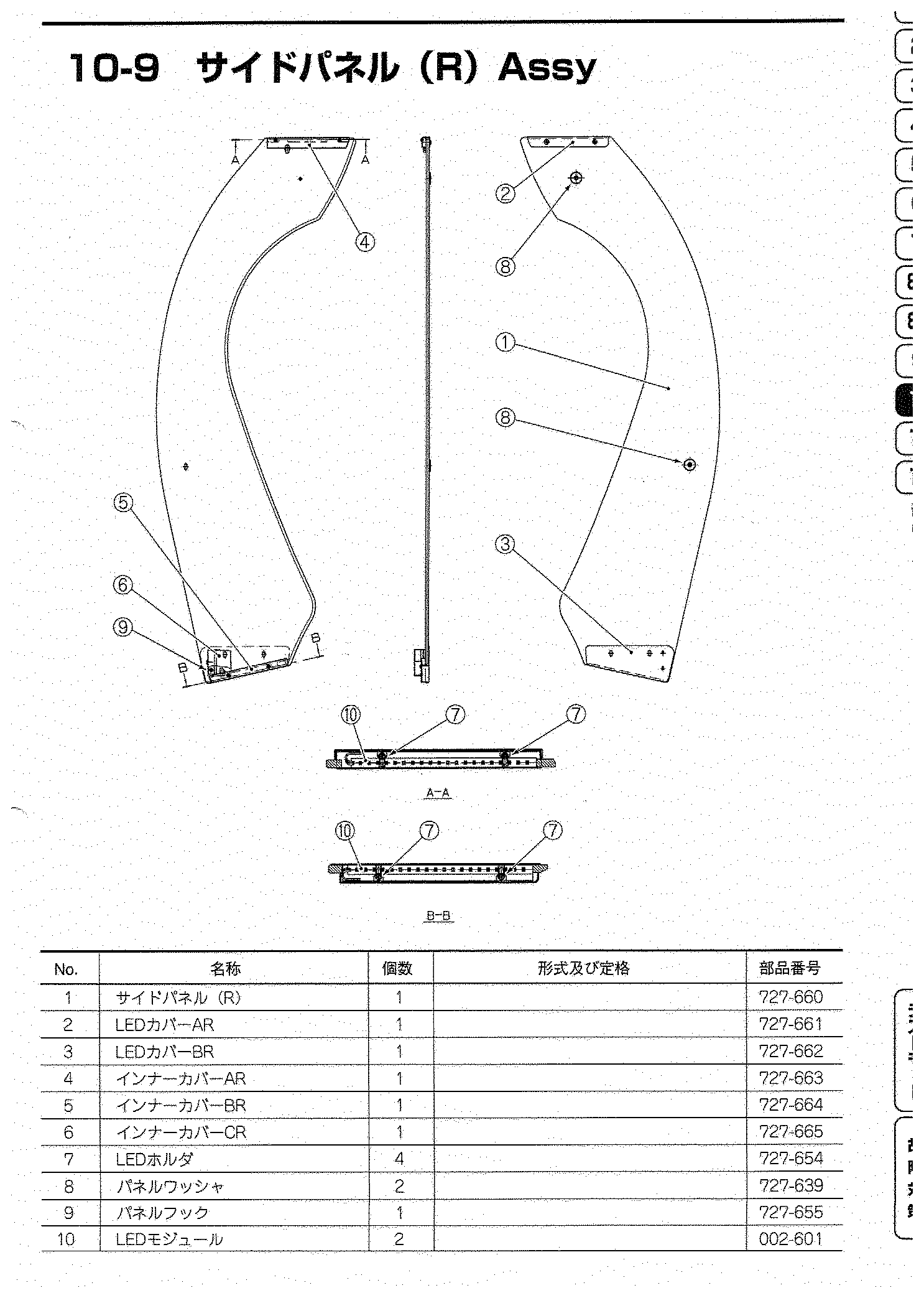
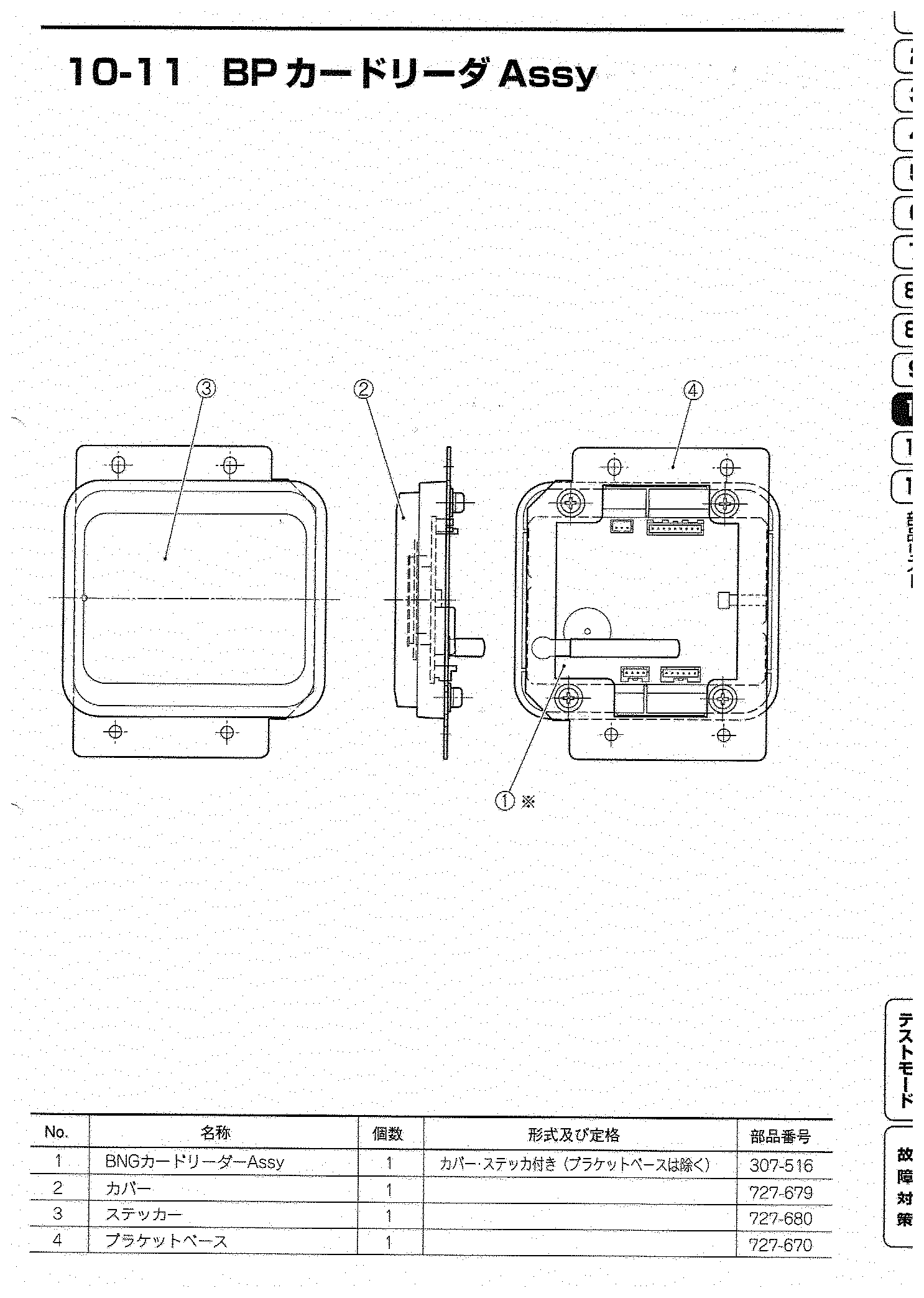
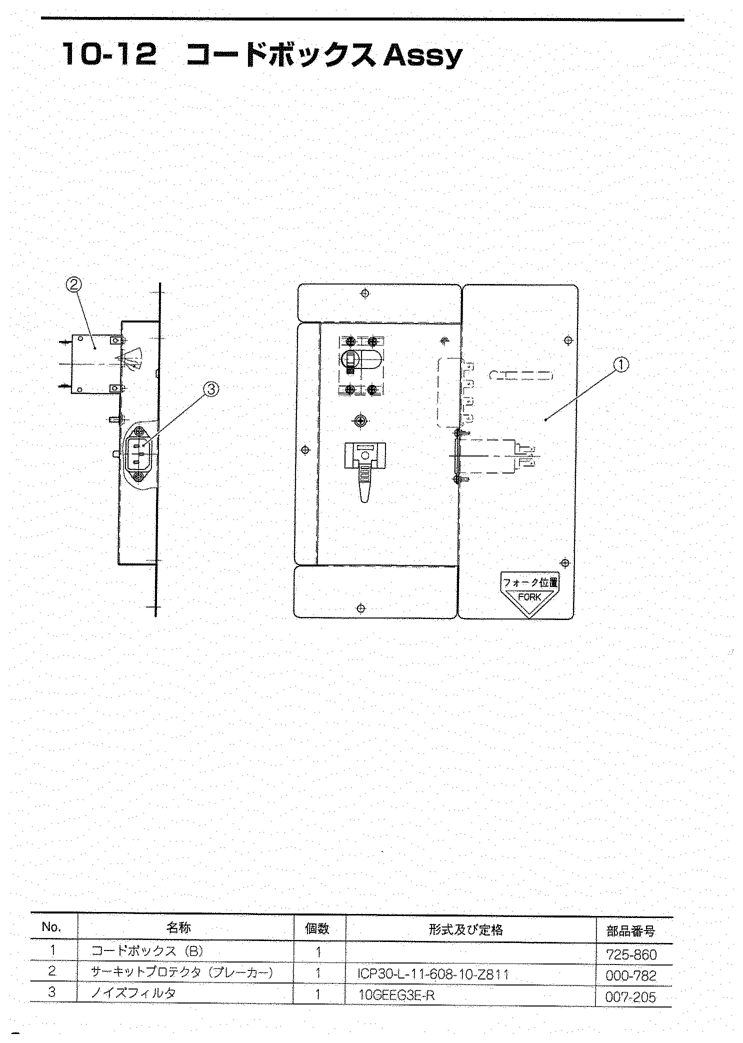
Manuals (archived)¶
- 📘 Operation manual, Dragon Ball ZENKAI Battle Royale (Japanese, 184 pages, 2011) — PDF
Status of the document
Bandai Namco Games document with no explicit licence, archived for preservation — the same position as the wiki's other manufacturer manuals. The filename uses the manual's real title, which is the game's.
Not recorded¶
Rated currents of the two regulators— resolved: the parts list (section 10-10) gives the references LGA100A-12-J1 and LGA150A-24-J1, more reliable than reading the diagram. See The two regulators above.Cabinet weight— resolved: the manual gives it, §2 仕様 (7) 重量, folio 11 (p. 13 of the PDF). See Weight above.- Full pinout of the S357 board connector: only pins 11 to 24 are legible (+5 V, PUSH 2-5, ANALOG 0-3, grounds).
Procedure — a cabinet that will not start ✅¶
This cabinet is documented as 100 V
It does not go straight onto a European socket. It needs a step-down transformer rated for the whole cabinet, monitor included — not a travel adapter. Feeding 230 V to a cabinet built for 100 V destroys the supply, and usually the monitor with it. → Cabinet power
What this adds
Ordered for a cabinet, not for a board: mains, low-voltage supply, loom, monitor, then the game. The overwhelming majority of "dead cabinets" are dead for a reason that has nothing to do with the PCB — which is why the board comes last here.
1. Mains, and what sits between it and the cabinet. The switch, the fuse or breaker, the isolation transformer if there is one. A cabinet that shows no sign of life at all is almost never electronic.
2. The low-voltage supply — measured under load. Aim for +5 V where power reaches the board — the JAMMA edge, or the JVS power connector, depending on the cabinet — with the game running, not on an idle bench. If the supply has an adjustment (most candy and JVS bricks do; the ATX brick in a PC cabinet does not), do it then and not before: set off-load, it leaves a board that boots and then glitches. With no adjustment the measurement still earns its keep — it tells you whether the supply holds. Check +12 V too, and −5 V if the board uses it: many do not, and an ATX brick does not provide it. → Cabinet power
3. The loom and the connector. Reseat, and check the grounds — a cabinet with a poor ground gives rolling picture, phantom inputs and noise, all at once, and none of it looks like a wiring fault. → Wiring
4. The monitor. This page describes the monitor as: 32″ LCD, 1920 × 1080, analogue / digital (HDCP) input. LCD: no high voltage, but a backlight that fades and a panel that is a consumable. A black screen with sound is usually the backlight or its supply, not the panel.
5. Scan rate — the mismatch that breaks nothing. If the board's rate is not one the monitor accepts, you get no picture and nothing is faulty. Check what this cabinet takes against what the board puts out before opening anything. → Modernising a cabinet
6. The control panel. Microswitches and the loom, in that order. A single dead direction is a switch; a whole player dead is the loom or its ground. → Control panels
7. Coin mech and sound. Last, because they hide nothing: a mech that no longer registers is usually dirty or misadjusted, and silence with a good picture points at the amplifier and its supply rails.
Photos / assets¶
(To add: whole cabinet, panel, power stage, BanaPassport reader, regulator labels.)
Sources & attribution¶
Primary source:
- Bandai Namco Games — ドラゴンボール ZENKAI バトルロイヤル operation manual (2011) — section 2 "仕様" (mains, consumption, screen, dimensions, cashbox), section 11 "配線図" (overall and cabinet diagrams: panel, OSD, card reader, RS-232 and audio pinouts, wire gauges), section 10 (parts list). Archived PDF
Existence and naming:
- Hard*Candy — Blanc Cabinet (lists the cabinet as "Namco Blanc", related to the Noir; no technical field filled in) — https://www.hard--candy.com/wiki/candy/Blanc_Cabinet
Differences between versions (colours, topper, column fan voltage, speakers, panel trim): recorded first-hand by gtranche, the wiki's owner, from cabinets he has seen. No written source consulted documents them — neither Arcade Otaku nor Hard*Candy. ⚠️ The v2 panel trim still needs confirming with a photo.
Images: dbz-cotes.png, dbz-regulateurs.png and dbz-panneau-eclate.png are
extracts from the manual (sections 2, 10-10 and 10-5), cropped and contrast-adjusted for
screen reading. The full manual is archived here, so these figures add nothing that is not
already present.
Diagrams: dbz-levier-5p.en.svg and dbz-boutons-12p.en.svg are drawn for
this wiki from section 11-2 of the manual. Pins the diagram leaves unwired are
marked n/a, never filled in by analogy.
Review & corrections
How this space is used
Spotted a wrong value, an outdated procedure, a chip reference that does not match your board? Say so here, with what you observed (model, board revision, serial number, measurement). Every report is cross-checked against a source before anything changes — an unverifiable correction is published as “reported by …, not cross-checked” rather than silently applied.
Reading is open to everyone; posting requires signing in with Discord. Reports from the wiki's declared reviewers are handled first; anyone else's are read too, but go through a human before anything is changed.