Control panels & buttons (layouts + wiring)¶
The control panel ("CP") carries the joystick and buttons. This page brings together the standard layouts (Vewlix, Sega, Neo-Geo…) and the real wiring: microswitches, Faston terminals, daisy-chained ground, to the JAMMA edge or the JVS I/O board.
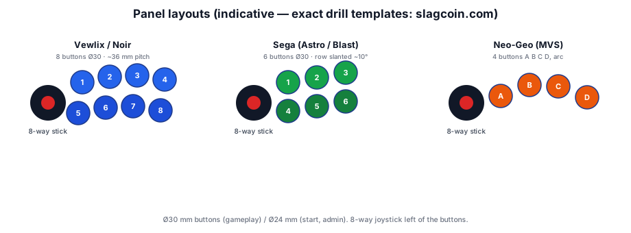
Button layouts (the big standards)¶
| Layout | Buttons | Geometry | Cabinets |
|---|---|---|---|
| Vewlix | 7 button holes (4 top, 3 bottom) + 1 start hole apart — 8 in all, 6 game buttons fitted ⚠️ | 2 rows, top row offset right, gentle curve; ~36 mm pitch | Taito Vewlix, most fightsticks (⚠️ not the Namco Noir, see its row) |
| Sega (Astro/Blast) | 6 | row slanted ~10°, flatter than Vewlix | Sega Astro City, Blast City, New Astro… |
| Neo-Geo | 4 (A B C D) | gentle 4-button arc | Neo-Geo MVS (SNK cabinets) |
| Namco Noir | 6 holes per player + start (counted on a unit) | Vewlix-like | Noir cabinets |
- Button diameter: Ø 30 mm for gameplay (Japanese standard: Sanwa OBSF-30, Seimitsu), Ø 24 mm for side functions (start, admin).
- Joystick: 8-way (Sanwa JLF, Seimitsu LS-32…), to the left of the buttons on a right-handed panel.
- Slagcoin is the reference for dimensioned templates (Vewlix, Sega, Astro, Hori…). Never invent a drill pattern — start from its template.
“Vewlix layout”: the Taito panel and the fightstick convention do not count the same
This page used to claim 8 buttons for the Vewlix. No source said so: Slagcoin, which we cite, publishes dimensioned templates and writes only "the precise layout used in Taito Vewlix cabinets" — with no button count. The 8 was this wiki's own addition.
Here is what the archived Taito documents say, and they agree with one another:
| Document | What it writes |
|---|---|
| Vewlix L flyer | ボタン穴は上段4、下段3の計7個 — 7 holes, 4 top, 3 bottom |
| L manual, folio 7 | 1ジョイスティック・6ボタン(1J7B) — 6 game buttons ⚠️ the 7B counts the buttons supplied, start included, not the holes |
| L manual, §4-3 | option VL コントロールパネル 2J14B【2ジョイスティック・14ボタン】 — 7 per player |
| C manual | 1ジョイスティック・6ボタン・スタートボタン — start is counted separately** |

§4-4-2 of the L's manual shows it: the play cluster has 7 holes with 6 fitted, the spare one is closed off with a supplied ボタンカバー, and start is a separate button at the lower right, outside the cluster.
So 7 + 1, not 8 in a line. The figure 8 circulates mostly about "Vewlix" fightsticks — ⚠️ no document is archived here for that, and we do not verify it — but whatever the stick market does, it is not the Taito cabinet's hole pattern. On a panel you are about to drill, the difference is one hole too many.
Vewlix: the spacing trap
On the Vewlix, some top-row buttons sit closer than 36 mm to each other → Sanwa screw nuts can clash. Plan for snap-in buttons or check the spacing before drilling.
Wiring a button¶
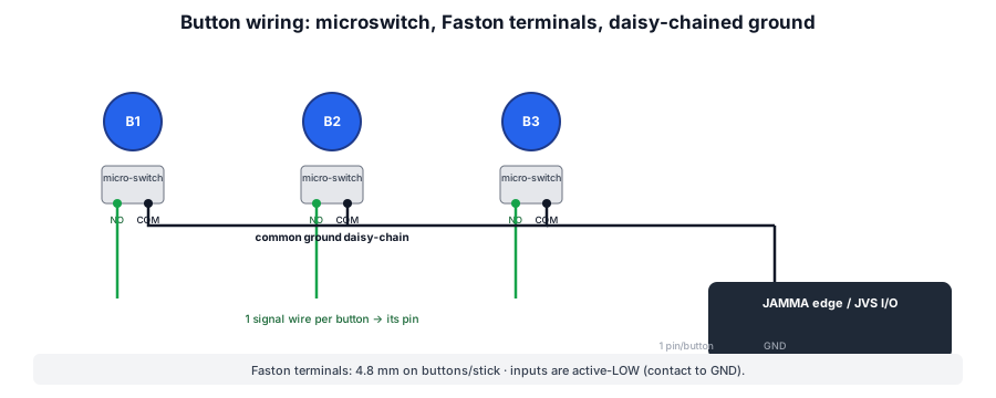
- Microswitch under each button, with 3 terminals: COM (common), NO (normally open), NC (normally closed, unused here).
- Active-low logic: the button ties its pin to ground when pressed. So you wire:
- COM → ground (GND),
- NO → the signal pin (button 1, 2, direction… on the JAMMA edge or the CN3 connector of the JVS I/O board).
- Daisy-chained ground: a single ground wire runs COM to COM across all buttons/directions, then joins one GND pin on the connector. Saves wiring and guarantees a common ground.
- Faston terminals: 4.8 mm (aka "110" / ".187") on buttons and joystick; sometimes 2.8 mm on some microswitches. Crimp cleanly (crimping tool).
Joystick¶
- 4 microswitches (up/down/left/right), wired like the buttons: COM to the common ground, each NO to its direction (Up/Down/Left/Right on the connector).
- Square restrictor (8-way) or octagonal; interchangeable gate per game.
- Some sticks have a 5-pin connector (4 dir + ground) instead of individual terminals.
Panel harness¶
- JAMMA: the CP wires to the edge's control pins (see JAMMA pinout) — active-low, ground on a GND pin.
- JVS: the CP wires to CN3 (60-pin) on the JVS I/O board — same principle (active-low, +5 V/GND supplied by the board).
- Interchangeable panel (Sega/Taito candy cabs): the CP unclips and reconnects via a multi-pin connector — hence the easy config swaps.
- Buttons 4/5/6 (6-button games): outside the 56-pin JAMMA → dedicated kick harness (see JAMMA).
The candy panel's extra-buttons connector¶
On Sega candy cabs the extra-buttons run between panel and base is a straight-through (signal-agnostic) cable of the AMP Universal MATE-N-LOK family. Two sizes:
- Astro / Blast City — 10-pin (buttons 4/5/6 for both players + GND, In-Line), see Astro City.
- Net City, New Net City, Naomi Universal — 15-pin (3×5 matrix): adds button 7 per player, plus +12 V / +5 V for lighting:
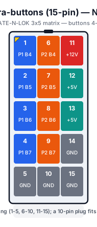
10 ↔ 15-pin compatibility
A 10-pin plug fits a 15-pin receptacle: an Astro panel (10-pin) works in a Naomi cabinet (15-pin). The reverse does not (a 15-pin plug won't fit a 10-pin receptacle).
Outputs (lit start, lamps)¶
On JVS, the I/O board drives +12 V outputs (lit start, billboard lamps, solenoids) via its output connector (see JVS I/O board). On JAMMA, only coin counters and lockout are provided; lighting runs on the cabinet's own harnesses.
→ Repair: PCB fault-finding · Traces & vias.
Sources & attribution¶
- slagcoin.com — Panel Layout (Vewlix, Sega, dimensioned Ø30/Ø24 templates, spacing) — ⚠️ gives no button count: the "8" this page attributed to it did not come from there — https://www.slagcoin.com/joystick/layout.html
- Taito — for the Vewlix layout's hole count (7 = 4 + 3, start separate): Vewlix L flyer (計7個), L manual folio 7 (1J7B) and part 2 §4-3 (the 2J14B option) and §4-4-2 (the drawing of the cluster and the ボタンカバー) — archived on the Vewlix page
- Arcade Otaku Wiki / GameSX — JAMMA & JVS wiring (active-low inputs, CN3) — https://gamesx.com/wiki/doku.php?id=arcade:jvs_board_connectors
- NFG Games / GameSX — Sega City cabinet pinouts (10/15-pin extra-buttons, 10↔15 compatibility) — https://gamesx.com/wiki/doku.php?id=arcade:sega_city_cabinet_pinouts
- Internal pages: JAMMA wiring · JVS I/O boards
Review & corrections
How this space is used
Spotted a wrong value, an outdated procedure, a chip reference that does not match your board? Say so here, with what you observed (model, board revision, serial number, measurement). Every report is cross-checked against a source before anything changes — an unverifiable correction is published as “reported by …, not cross-checked” rather than silently applied.
Reading is open to everyone; posting requires signing in with Discord. Reports from the wiki's declared reviewers are handled first; anyone else's are read too, but go through a human before anything is changed.