Philips Videopac G7000 and Videopac+ G7400¶
Philips' 8-bit console (1978-1983), sold under thirteen names across Europe, the United States and Brazil. The 1983 G7400 adds a second graphics processor and overlays two pictures — an unusual architecture, and the reason some G7000 games stop working on it.
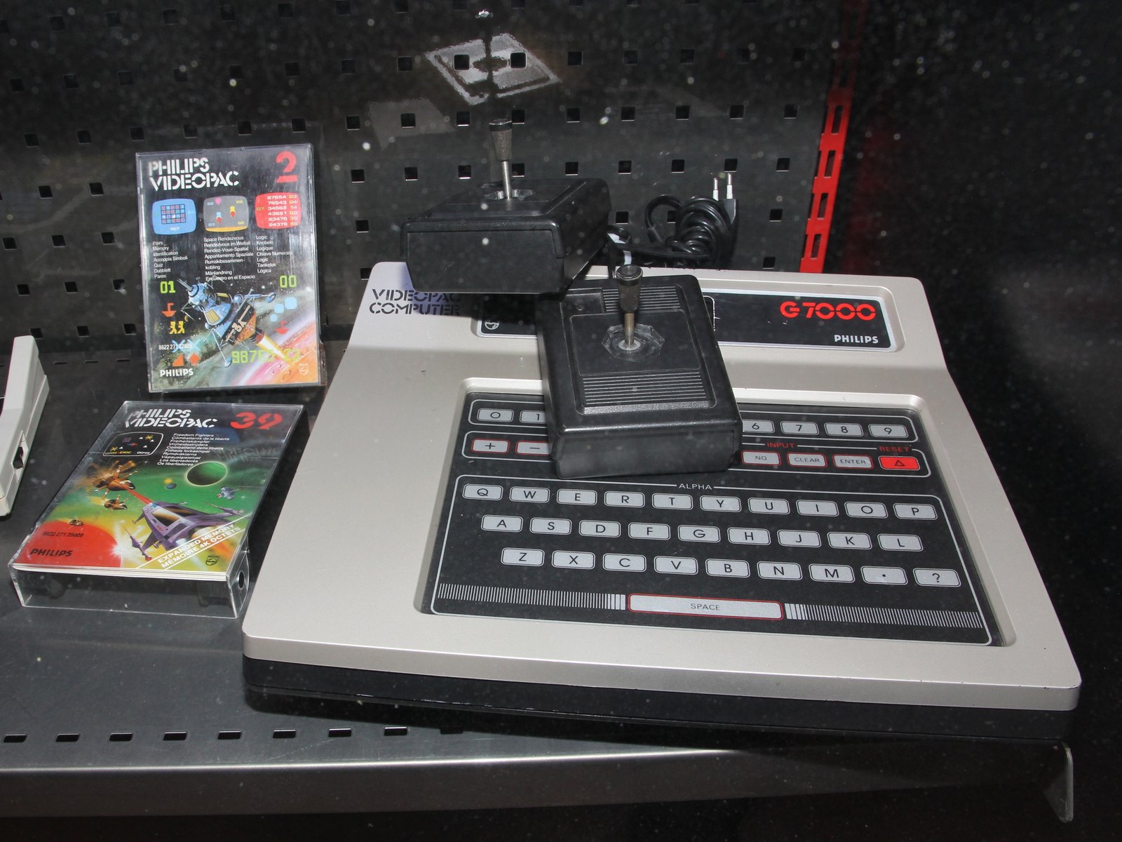
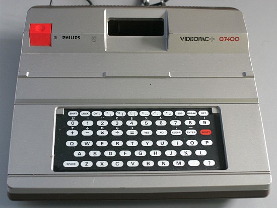
Identification¶
| Field | Value |
|---|---|
| Manufacturer | Philips (Magnavox in the US, a Philips subsidiary at the time) |
| Years | 1978-1983 |
| CPU | Intel 8048 — 1 KB ROM and 64 bytes RAM internal |
| RAM | 128 bytes (6810) |
| Video and sound | Intel 8244 (NTSC) / 8245 (PAL) |
| Media | cartridge |
| Inputs | 2 joysticks (hardwired or on connectors) + keyboard |
What the G7400 adds¶
| Field | Value |
|---|---|
| I/O expander | Intel 8243 |
| Graphics | EF9340 + EF9341 (Thomson) |
| VRAM | 6 KB (three 2128s) — ⚠️ only 4 KB are used |
| Keyboard | larger |
Two overlaid pictures
The G7400 does not replace the 8245: it complements it. The EF9340/EF9341 pair produces a background, which the original chip then covers with its sprites. The Philips manual devotes a whole chapter to the "insertion of the GEN and VIN picture (scenery) into the VDOP picture (game)", transparency handling included.
Name mapping — the manual refers to the chips by initials: VIN = EF9340 (counters, addressing, serialisation) and GEN = EF9341 (character generator in ROM and the "letterbox"). The 8245 is called the VDOP. Philips presents them as an ANTIOPE / TELETEXT-type generator.
⚠️ The crystals change with the model¶
This is the measurement trap on this family: six different configurations, and the MAME driver lists them one by one.
| Model | Crystal |
|---|---|
| Magnavox Odyssey² (US) | 7.15909 MHz |
| Videopac G7000 (Europe) | 17.734476 MHz |
| Videopac C52 / Videojeu N60 (France) | 17.812 MHz |
| Videopac G7200 (built-in B/W screen) | 5.911 MHz + 3.547 MHz |
| Videopac+ G7400 | 5.911 MHz + 8.867 MHz (MAME) — ⚠️ the manual states 8.906 MHz |
| Jopac JO7400 (Brandt, France) | 5.911 MHz + 3.5625 MHz |
Expected clocks on a G7400 ✅¶
| Component | Frequency | Source |
|---|---|---|
| Intel 8048 | 5.911 MHz | crystal, undivided |
| Intel 8245 (VDOP) | ~3.5468 MHz (MAME) · 3.56 MHz (manual) | 8.867 × 2 ÷ 5 |
| EF9340 (VIN) | ⚠️ ~3.5 MHz, and gated | see below |
How the G7400 displays, per the manual
The Philips manual (§ IV-3) describes GEN and VIN display in the European standard: 40 cells per row over 25 rows, that is 1,000 cells. Each cell occupies 10 TV lines, each slice 8 dots, and the scan is not interlaced.
§ IV-3.1: a TV line holds 40 luminance columns and 16 blanking columns, that is 56 columns in 64 µs. At 8 dots per column that gives 448 dots per line and 7 million dots per second. The manual concludes: "each dot corresponds to a half-period of a 3.5 MHz clock".
The character set fits in 9 bits (128 alphanumeric + 128 semigraphic + 192 definable in RAM) and the attributes in 7 bits, hence 16 bits per cell of screen memory.
The VIN's and the VDOP's clocks are not the same — a measurement trap
The manual (§ V-2, folio 65) is explicit: 228 clock periods in 64 µs are needed for the VDOP and 224 in the same time for the VIN, that is 3.56 MHz against 3.5 MHz — obtained by dropping 4 periods every 228.
In other words the VIN is briefly halted on every line, waiting for the VDOP. A frequency counter on the VIN of a healthy machine will therefore read less than on the 8245. That is not drift.
The family — one machine, thirteen names¶
Videopac / Odyssey² (8244/8245 base)
| Name | Market |
|---|---|
| Videopac G7000 | Europe, several models |
| Odyssey² | United States (Magnavox) |
| Videopac C52 | France |
| Videojeu N60 | France |
| Radiola Jet 25 | France |
| Siera Videopac Computer G7000 | France |
| Schneider Videopac 7000 | Germany |
| Philips Odyssey | Brazil |
| Videopac G7200 | Europe — built-in black-and-white screen |
Videopac+ (with EF9340/EF9341)
| Name | Market |
|---|---|
| Videopac+ G7400 / G7401 | Europe |
| Brandt Jopac JO7400 | France |
| Schneider Videopac 74+ | Germany |
| Odyssey³ Command Center | United States — ⚠️ prototype; MAME gives its clocks as unverified |
⚠️ Compatibility: what does not carry across models¶
Four compatibility points noted by MAME
- Blackjack (Videopac 5) does not work on the G7400. This is not wear and not a faulty cartridge: a BIOS routine was removed on this machine. No point cleaning the contacts.
- G7400 games look wrong on the Odyssey³ and vice versa: the EF9340 graphics sit lower on the Odyssey³.
- Jopac JO7400: its different crystal ratio produces glitches on games that change the video mid-screen, "notably backgamm" — a concrete test title for anyone who owns this machine.
- 4in1 and musician are not supposed to work on the G7400. MAME notes they nonetheless run fine in the emulator, and offers a hypothesis — bus conflict, or writing to P2 — without settling it.
Common faults¶
| Symptom | Likely cause | Lead |
|---|---|---|
| Won't start | 8048 or its crystal | ⚠️ the value depends on the model — see the table |
| No picture (G7000) | 8244 / 8245, or the modulator | 8244 on NTSC, 8245 on PAL: do not mix them up. ⚠️ On a G7400, see the next row |
| Completely black screen (G7400) | ⚠️ VIN or VDOP — see below | Mutual dependency: the VDOP is slave to the VIN, but the VIN is blocked without the VDOP's HSY |
| Wrong characters, correct colours at the faulty locations | character code RAM (ref. 667) | Signature given by the manual |
| Characters correct, or replaced by semigraphics of arbitrary colour | attribute RAM (ref. 666) | Same |
| All normal except the special scenery characters | extension RAM (ref. 671) | Same |
| One specific cartridge won't run | ⚠️ may be normal | See the incompatibilities above |
| Keyboard partly dead | 74LS156 (decoder, column select) / 74LS148 (priority encoder, return) or the matrix | ⚠️ not the 8243 — see below |
| The 12 extra keys do not respond | ⚠️ may be normal | The keyboard goes from 49 to 61 keys; the new ones sit on columns 6-7, meant for the 7420 cartridge's BASIC, and "are not read by the keyboard-scanning routine of most games" (folio 8) |
On the G7400 the two video chains are NOT independent
Contrary to what one might assume, the VDOP (8245) is slave to the VIN. The manual is explicit: without the VIN's TL pulse, "the video processor stays in slave mode and generates no picture, unlike the C.52".
A dead VIN therefore does not give "background missing, sprites fine" but a completely black screen.
⚠️ And the reverse holds: without the VDOP's HSY the VIN is blocked for want of a clock (§ VI-2, folio 74). A black screen therefore points at neither of them — only the two isolation procedures below settle it.
Procedure — a dead console, step by step ✅¶
What this adds
Ordered for a console, not for an arcade board: what kills these is almost never the CPU. It is, in real order, the power supply, the capacitors, the drive or the cartridge slot, and only then the logic. → PCB diagnosis
1. The power supply. Two cases, depending on the machine. External brick: ⚠️ read the marking on the machine, next to the socket, and check the adapter against it — voltage and polarity. A centre-negative machine fed centre-positive loses its fuse, sometimes its regulator; do not trust a third-party label or a generic tip. Internal supply (the machine plugs straight into the wall): mains is inside the shell. Unplug, wait, and confirm the large capacitors are discharged before touching the board. Either way, measure under load: a failing supply holds its voltage until it is asked for current.
2. The fuse. Many of these machines have one right behind the socket — it is the part designed to die. Test it in continuity, out of circuit. A fuse that blows again is a short, not a fuse problem.
3. Capacitors. On most machines of this age this is the default suspect rather than a last resort — leaking SMD electrolytics eat the tracks underneath before they give any other sign. ⚠️ Not all of them are like that: some carry very few and are not recapped on principle. Read what this page says about it before reaching for the iron. → Recap
4. The cartridge connector. Cartridge contacts with isopropyl alcohol, never an abrasive eraser: it takes the gold plating off and the problem comes back worse. On the machine side, inspect the slot pins — splayed, bent or oxidised — and check continuity between slot and board.
5. Video output. Isolate the machine from the display: another cable, another TV, another input. A sizeable share of "dead consoles" are a dead cable, or a display that will not lock onto what this machine outputs — see the video section of this page for what that is.
6. Still nothing. Now, and only now, the logic: rails on the board, reset, clock, bus. → PCB diagnosis
Parts shared with the original Videopac ✅¶
The manual (folio 7) lists what is "absolutely identical" to the C.52, adding: "same parts for maintenance". It is therefore a list of parts that can be taken from an original Videopac.
| Block | Component |
|---|---|
| Video | VDOP 8245 and its interface logic to the microprocessor |
| Memory | 6810 RAM and its control circuits |
| Controllers | DIN-socket handsets (as on the G7200 / Jet 27) and 74LS365 buffers |
| Keyboard | 74LS156 and 74LS148 — the manual writes "encoder and decoder" without saying which is which; MAME and the datasheets make the 156 the decoder and the 148 the priority encoder |
| Interrupts | A1 address decoder |
| Cartridge | the connector and its pinout — ⚠️ to within one pin |
| Scan | the 50 extra lines counter, 74LS393 |
The 8048 must NOT be taken from a C.52
That is the exception, and the manual flags it: "This machine cannot work with a C.52 8048, because the use of GEN and VIN is essential to get a picture."
The G7400's 8048 has a modified internal program — it initialises GEN and VIN and displays "QUEL JEU ?" through them. The subroutines, however, are unchanged, since the older cartridges use them.
Swapping the 8048 with one from an original Videopac is therefore a dead end that costs a stripped machine for nothing.
The address latch, useful while checking ALE
The address latch is a 74LS373: transparent during the high level of the clock rather than on an edge. The address therefore appears earlier and is unstable on the bus during ALE. Worth knowing before concluding anything from watching the address bus at ALE time.
Cartridge compatibility — what Philips says, and what MAME says¶
The manual (folio 3) claims double compatibility:
- older Videopac cartridges run on the G7400 "exactly as on a C.52";
- Videopac+ cartridges can be used on the older consoles, "since only the VDOP's objects take an active part in the game" — you lose the scenery, not the game.
A documented exception Philips does not mention
The MAME driver notes that Blackjack (Videopac 5) does not work on the G7400, "caused by a removed BIOS routine".
The two sources therefore contradict each other on this precise point: Philips claims full compatibility for older cartridges, MAME documents at least one title that escapes it. We set them side by side rather than picking one — but for a technician the practical consequence is the same: an old cartridge that refuses to start on a G7400 is not necessarily a fault.
No picture at all — Philips procedure ✅¶
The manual gives its own check sequence (folio 76, Fig. 51), with pin numbers. It runs after pressing "△" and selecting a game.
| # | Check | If it fails |
|---|---|---|
| 1 | 5 V and 12 V present on the wires leaving the power supply | Power supply or a short circuit |
| 2 | ALE (2.5 µs period) on pin 11 of the 8048 | The 8048 or its 5.93 MHz clock on pin 2 |
| 3 | HSY (positive line pulse) on pin 5 of the VDOP 8245 | The VDOP or its 3.56 MHz clock on pin 1 |
| 4 | Clock Ø (0.28 µs period) on pin 5 of the VIN 9340 | The 660 A flip-flop |
If all four checks pass
The manual concludes: the problem then lies in the 8048 and its link to GEN and VIN (check the free-run), or in GEN and VIN and their ST, VE and B5-B7 data bus lines.
And it gives the way to tell the two blocks apart: switching to the C.52 configuration described in its § VI-1. The machine then behaves like an original Videopac, which isolates the GEN/VIN block.
Switching to the C.52 configuration — the exact procedure (§ VI-1)
⚠️ When to do it: the manual reserves it for the case where the machine gives a black picture at power-on, after reset and game selection. That is precisely the symptom the procedure above opens with.
- Remove the VIN (9340).
- Solder a wire between pin 5 (HSY) of the VDOP 8245 and pin 25 (TL) of the VIN — to feed a signal to the 50-line counter.
- Move one end of resistor 714 (1 Ω), next to the GEN 9341, to inject correct sync pulses towards the television (figure 49 in the manual).
The manual explains why this works: the line sync signal TL (pin 25 of the 9340) only exists once the VIN's R register has been loaded. Its presence therefore proves in one go that the 8048 talks to the GEN, that the GEN's letterbox works, that the VIN works, and that the GEN↔VIN link (ST, VE, B5-B7 of the data bus) is sound.
Making the VIN's picture visible without the VDOP (§ VI-2)
A second, different manipulation: if the VDOP supplies no HSY, the VIN is blocked for want of a clock. Its picture can still be brought up:
- tie the VDOP's HSY to ground (pin 5 of the 8245) — this puts the 3.56 MHz clock on the VIN;
- tie the BLK wire to ground (pin 39 of the 8048) — this enables the transparency multiplexer.
⚠️ The resulting picture is not usable, as there is no frame sync (supplied by the VDOP). But it checks the GEN-VIN and the 8048, which is the point.
The manual's clocks corroborate MAME's
5.93 MHz at the 8048 and 3.56 MHz at the 8245 given by the manual as expected values — they are the referrals in its "if it fails" column, not claimed measurements — against 5.911 MHz and ~3.5468 MHz derived from the crystals by the driver. Two independent sources, the same values to within rounding.
Repair (technician)¶
- Identify the model before measuring. Six crystal configurations: on this family, measuring without knowing which machine you have proves nothing.
- 8244 or 8245 depending on the standard: the video chip differs between NTSC and PAL.
- ⚠️ Do not conclude from a black screen that the VIN is dead. The dependency is mutual: without the VIN's TL pulse the VDOP stays slave and shows nothing (§ VI-1); but without the VDOP's HSY the VIN is blocked for want of a clock (§ VI-2). A black screen therefore localises nothing on its own — the two isolation procedures above are what settle it.
- What the 8243 actually does: it holds the two control latches for the mix — ports 4-5 for highlighting, ports 6-7 for transparency. The mixing itself is done by a 74LS151 and a 74LS157: that is where to look, not at the 8243. ⚠️ It reads no key, but it sits on the same P20-P23 pins as the keyboard's column select — only the PROG strobe separates them.
- The G7400's VRAM is only two-thirds used (4 KB of 6, per MAME). ⚠️ Do not conclude that a third of the memory is inert: the manual gives a visible fault signature for each of the three RAMs (see the faults table). The 2 unused KB are spread over half-filled packages, not a free one.
→ Methods: PCB diagnosis · Recap
Modernisation & mods¶
- ⚠️ Do not host ROMs — method only.
Archived manufacturer documentation ✅¶
- Videopac+ — Philips technical manual — PDF (71 pages, French)
This document is a Philips technical training manual, not a user guide: it details video signal generation, how the character generator and the screen memory work, the insertion of the background picture into the game picture, and transparency handling.
Status
A manufacturer document with no explicit licence, kept for preservation (machine out of production for decades).
Sources & attribution¶
Text (synthesis; sources listed for attribution):
- MAME —
src/mame/philips/odyssey2.cpp(BSD-3-Clause, driver by Peter Trauner, Wilbert Pol and hap): the Intel 8048 with its 1 KB ROM and 64 bytes of internal RAM, the 128 bytes of RAM (6810), the Intel 8244 (NTSC) / 8245 (PAL) for video and sound; for the G7400, the Intel 8243, the EF9340 + EF9341 and the 6 KB of VRAM (3×2128, of which 4 KB are used); the six crystal configurations listed model by model; the G7400's clocks — 8048 at 5.911 MHz, EF9340 and 8245 at 8.867 × 2 ÷ 5; the full list of variants and the prototype status of the Odyssey³; and the three documented incompatibilities: "Blackjack (Videopac 5) does not work on G7400, caused by a removed BIOS routine", "G7400 games don't look correct on odyssey3 and vice versa: ef934x graphics are placed lower on odyssey3", "due to different XTAL ratio on Jopac JO7400, some games that do mid-screen video updates will have glitches" — https://github.com/mamedev/mame/blob/master/src/mame/philips/odyssey2.cpp - Philips technical manual — Videopac+ (archived:
manuels/videopac-plus-g7400-manuel-technique.pdf): § IV-3 — GEN and VIN display in the European standard: 40 cells per row over 25 rows (1,000 cells), 10 TV lines per cell, 8 dots per slice, non-interlaced scan; § IV-3.1 — 40 luminance columns and 16 blanking columns, that is 56 columns in 64 µs, 448 dots per line and 7 million dots per second, each dot being "a half-period of a 3.5 MHz clock"; § IV-3.2 — the 9-bit character code and 7-bit attributes, hence 16 bits per cell; the VIN = EF9340 and GEN = EF9341 mapping with their respective roles, the 8245 being called the VDOP; chapter VI — the VDOP stays slave and generates no picture without the VIN's TL pulse, and the three memory fault signatures (character code, attribute, extension); folio 3 — the claimed double compatibility (older cartridges "exactly as on a C.52", Videopac+ cartridges usable on the older consoles "since only the VDOP's objects take an active part"); folio 7 — the list of parts "absolutely identical" to the C.52 and therefore interchangeable in maintenance (VDOP 8245, 6810 RAM, DIN handsets and 74LS365 buffers, 74LS156 encoder and 74LS148 decoder, A1 decoder, cartridge connector "to within one pin", 74LS393 counter), the remark "This machine cannot work with a C.52 8048" and the 74LS373 address latch whose address is unstable during ALE; the "no picture at all" troubleshooting procedure from folio 76, Fig. 51 — four checks with pin numbers (5 V/12 V, ALE 2.5 µs period on pin 11 of the 8048, HSY on pin 5 of the VDOP 8245, clock Ø 0.28 µs period on pin 5 of the VIN 9340) and their fault referrals, down to the 660 A flip-flop; § VI-1 — the C.52 configuration switch in detail (remove the VIN 9340, solder a wire between pin 5 (HSY) of the 8245 and pin 25 (TL) of the VIN, move one end of the 1 Ω resistor 714 next to the GEN 9341), its trigger condition ("black picture at power-on after reset and game selection") and what the presence of the TL signal (pin 25 of the 9340) proves, since it "only exists once the VIN's R register has been loaded"; § VI-2 — bringing up the VIN's picture by tying HSY to ground (pin 5 of the 8245) and the BLK wire to ground (pin 39 of the 8048), a picture "not usable as there is no frame sync" but which checks the GEN-VIN and the 8048; § VI-3 — the three RAM signatures with their board designators 667 (character code), 666 (attribute) and 671 (extension), and the note that "these 3 RAMs can be written and read by the 8048 with a test program"; § V-2, folio 65 — 228 clock periods in 64 µs for the VDOP against 224 for the VIN, that is 3.56 against 3.5 MHz, the VIN being briefly halted on every line; folio 8 — the keyboard going from 49 to 61 keys, the 12 new ones on columns 6-7 meant for the 7420 cartridge's BASIC and "not read by the keyboard-scanning routine of most games"; folios 14 and 18 — the 8243 holds the latches for highlighting (ports 4-5) and transparency (ports 6-7), the mixing itself being done by a 74LS151 and a 74LS157; ⚠️ Fig. 45, folio 67 gives the second crystal as 8.906 MHz where MAME uses 8.867 MHz — a discrepancy flagged on the page, left unresolved; and the expected values announced in its "if it fails" column: 5.93 MHz on pin 2 of the 8048, 3.56 MHz on pin 1 of the 8245, 0.28 µs period on pin 5 of the VIN — independently corroborating the MAME driver's values. ⚠️ The 5 MHz / 32 character figures previously published here came from a generic worked example in the manual (§ IV-2.1) and did not describe the G7400
Image:
-
videopac-g7400.jpg— Marco van den Hout, CC BY-SA 3.0 — https://commons.wikimedia.org/wiki/File:Philips_Videopac_G7400.jpg -
videopac-g7000.jpg— MKFI, Public domain — https://commons.wikimedia.org/wiki/File:Philips_Videopac_G7000_Tietokonemuseo.JPG


Review & corrections
How this space is used
Spotted a wrong value, an outdated procedure, a chip reference that does not match your board? Say so here, with what you observed (model, board revision, serial number, measurement). Every report is cross-checked against a source before anything changes — an unverifiable correction is published as “reported by …, not cross-checked” rather than silently applied.
Reading is open to everyone; posting requires signing in with Discord. Reports from the wiki's declared reviewers are handled first; anyone else's are read too, but go through a human before anything is changed.