Konami System 573
Konami arcade platform (1998), based on the PlayStation (PS1). It's the heart of the Bemani line: Dance Dance Revolution, Beatmania, GuitarFreaks, DrumMania. The CD-ROM + flash + security cartridge chain (paired to the I/O board) is the real preservation stake.
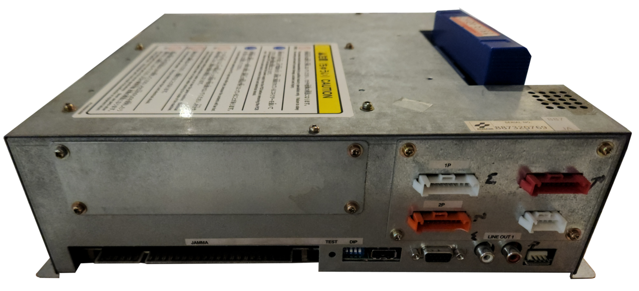
Identification
| Field | Value |
|---|---|
| Manufacturer | Konami |
| Year | 1998 |
| Base | Sony PlayStation (PS1) |
| Variants | Analog 573 · Digital 573 |
| Media | CD-ROM + onboard flash + security cartridge (+ PCMCIA / HDD per game) |
Architecture (≈ PS1)
| Block | Chip | Clock | Role |
|---|---|---|---|
| CPU | MIPS R3000A | ~33.9 MHz | PlayStation base |
| GPU | Sony custom (PS1) | ||
| Sound | PS1 SPU | + CD-DA for music | |
| Media | CD-ROM + flash ROM (install) + security cart | some games: PCMCIA or HDD (late DDR) | |
| I/O | Konami I/O board | DDR dance-pad, guitar, turntable, drum readers… |
Analog 573 vs Digital 573
- Analog 573 (base): the first generation, for Beatmania and the early titles (classic sample/CD-DA audio).
-
Digital 573: adds the Digital I/O board, which brings two major things:
-
(Encrypted) MP3 audio: a Micronas MAS3507D decoder driven by a Xilinx XCS40XL (Spartan-XL) FPGA + 24 MB of DRAM; MP3 files are preloaded then decrypted on the fly (key1/2/3 depending on the game). This is what enables the long DDR/ GuitarFreaks soundtracks without continuous CD reading.
-
Extended I/O: more I/O, RS-232 and ArcNet transceivers (cabinet-to-cabinet link), 128 KB of SRAM cache.
This board is paired to the security (see below).
Security & preservation (the real topic)
Security is the crux of the 573:
- Each game has a security cartridge holding a key (X76F041 EEPROM on the early ones, ZS01 later) + a serial number.
- That serial is paired to the game's digital I/O board → cartridge and I/O board go together. Without the right combination, the game won't start.
- Anti-cloning: the Digital I/O carries a DS2401 serial chip; it prevents using the same security cartridge on more than one 573. Hence, for preservation, you must dump the cartridge AND know the board's serial.
- Installation often copies data to the onboard flash; some games add a PCMCIA card or an HDD.
e-Amusement network
Some late Bemani connect to Konami's e-Amusement service via a network card in the lower PCMCIA slot: a system-on-a-chip running a customised NetNucleus (Toshiba), downloading data to a 20 GB IDE HDD. The service being closed, these titles are network-dependent → a separate preservation topic.
Open-source tool archived here
The 573in1 tool dumps/writes flash, PCMCIA, RTC and edits the serial (to move/ reuse a cartridge). Source archived: → System 573 install/converts guide (573in1, X76F041/ZS01, serial).
Bemani peripherals
Through its I/O board the 573 drives dedicated controllers — often built into the cabinet: dance pads (DDR, inputs + the floor/cabinet lamps driven by the Digital I/O), turntables + keys (Beatmania), guitars (GuitarFreaks), drums (DrumMania). The I/O wiring and the lighting are an integral part of the game — worth knowing when restoring a full cabinet.
Notable games
The Dance Dance Revolution, Beatmania / Beatmania IIDX (early), GuitarFreaks, DrumMania, Pop'n Music (some) series… the late-90s Bemani base. → Detailed catalogue: Konami 573 — 148 Bemani games.
Faults & preservation
- Worn CD drive → erratic reads (repair/image, or a modern solution).
- Security cartridge / flash: contacts, key; the I/O board pairing is critical.
- Battery (PS1 RTC/config); targeted recap.
- Emulation: MAME (
konami/ksys573.cpp) emulates the 573 and its security. No FPGA/MiSTer core (a PS1 base + Bemani peripherals).
Modernisation & mods
The common ground for every JAMMA board
Video, power, control panel and upscalers depend on the cabinet rather than the board: everything is centralised in Modernising a cabinet. To run the board outside a cabinet (at home, on a display): supergun.
- Battery 🟢: a save battery is fitted (settings/counters/RTC). A leaking battery corrodes traces — check and replace it before it leaks → save batteries.
- Optical storage 🟡: the drive is the number-one wear part. Modern routes: an ODE, netboot, or replacement by flash storage depending on the platform → PCB preservation hub.
- Scan rate 📺: PlayStation-based (Sony GPU) → standard ~15 kHz output, a 15 kHz chassis is fine. (Derived from the platform documented above — the screen configuration lives in the GPU device rather than the driver, so it is not measured here.)
- FPGA / emulation: see the Emulation & FPGA section below.
Repair (technician)
- Security cartridge: required to boot (per-game security, see the dedicated section). Without the correct security cart it won't start — not a hardware fault.
- CD-ROM: drive/laser = a weak point (DDR games hammer it) → optical cleaning.
- Onboard flash / PCMCIA / HDD: game install; storage wear.
- PS1 base: recap, GPU/RAM. Capacitors: recap PSU/audio.
→ Methods: PCB fault-finding · Recap · EPROM · Traces & vias
DIP settings ✅
1 games on this platform, settings extracted from the MAME sources (INPUT_PORTS_START blocks). The Position column gives the switch's physical reference on the board (SW2:!3,!4 = bank SW2, levers 3 and 4) — which is what lets you set it up without the paper manual. Games are sorted by MAME set name.
DIP settings — MAME set konami573
| Setting | Position | Options (default in bold) |
|---|---|---|
| Unused 1 | DIP SW:1 | Off · On |
| Screen Flip | DIP SW:2 | Normal · V-Flip |
| Unused 2 | DIP SW:3 | Off · On |
| Start Up Device | DIP SW:4 | CD-ROM Drive · Flash ROM |
Check against your own board
These settings apply to the game and revision described by MAME. One title may have several DIP sets depending on region or revision, and some systems use soft-dips (settings in memory, via the test menu) rather than physical switches. In case of a discrepancy, the board's silkscreen and the test menu are authoritative.
See also: DIP reference · game manuals
Procedure — a dead board, step by step ✅
What this adds
The general method lives in PCB diagnosis. This is its application to this platform: the same order, but with the values actually expected here, so you do not have to go back and forth.
Tools: multimeter, oscilloscope (or frequency counter), current-limited bench supply, desoldering braid. → Tooling
If the board is still in a cabinet
A CRT holds its charge with the machine unplugged. → CRT safety
1. Inspection, power off. Corrosion, cut tracks, oxidised EPROM legs, leaking SMD capacitors, dubious earlier repairs.
2. The connector, before anything else. A large share of "dead boards" are a contact problem, not a fault. Clean the contacts with isopropyl alcohol and reseat — not with an abrasive eraser on a gold edge, which takes the plating off and brings the problem back worse. It costs two minutes and settles the question.
3. Power, measured on the board. Aim for +5.0 V measured as close as possible to where power reaches the board — not at the PSU output: the drop is in the loom, and that is exactly what makes a board boot on the bench and not in the cabinet. Where you probe depends on this board's connector — JAMMA edge, JVS loom or a proprietary harness — plenty of makers kept one long after JAMMA arrived — see Identification above. → Wiring Check −5 V and +12 V too if the sound stage uses them. Suspected short: bring it up current-limited and find the hot spot.
4. /RESET. It must release after power-up. Held low = the CPU never starts. A 1–2 Hz loop is not the reset circuit, it is the watchdog: the CPU is crashing at boot, so look at the bus, not at the reset.
5. Clocks. There is no measurement table for this platform — MAME's sources yield nothing usable for it. Any frequency quoted under Architecture on this page serves as a marker; otherwise compare against a working board rather than against a number: an invented value condemns healthy parts. → PCB diagnosis
6. Bus. Activity on the main CPU's address lines tells you whether it is running or frozen. Frozen with good clocks and good reset → work RAM, bus buffers, ROMs.
7. It boots but the picture or the sound is wrong — that is another job: see Common faults on this page, then signal tracing.
Lineage
PlayStation kinship with the Capcom ZN and the Taito G-NET (same Sony arcade bases).
Photos / assets
(To add: 573 board, security cartridge, digital I/O board, CD drive.)
Sources & attribution
- Wikipedia — Konami System 573 (PS1 base, Analog/Digital, CD + flash + X76F041/ZS01 cartridge + paired serial, Bemani) — CC-BY-SA — https://en.wikipedia.org/wiki/Konami_System_573
- MAME —
konami/ksys573.cpp(security, catalogue) +k573dio(Digital I/O, encrypted MP3, MAS3507D) — https://github.com/mamedev/mame - psx-spx (consoledev) — Konami System 573 (Digital I/O: XCS40XL FPGA, MAS3507D, 24 MB DRAM, ArcNet, DS2401; e-Amusement NetNucleus/20 GB HDD) — https://psx-spx.consoledev.net/konamisystem573/
- Internal page: Converts / 573in1
Image:
-
system573-front.png— Jhonny, CC BY-SA 4.0 — https://commons.wikimedia.org/wiki/File:Bemani_System_573.png

Review & corrections
How this space is used
Spotted a wrong value, an outdated procedure, a chip reference that does not match your board? Say so here, with what you observed (model, board revision, serial number, measurement). Every report is cross-checked against a source before anything changes — an unverifiable correction is published as “reported by …, not cross-checked” rather than silently applied.
Reading is open to everyone; posting requires signing in with Discord. Reports from the wiki's declared reviewers are handled first; anyone else's are read too, but go through a human before anything is changed.