Sega Astro City
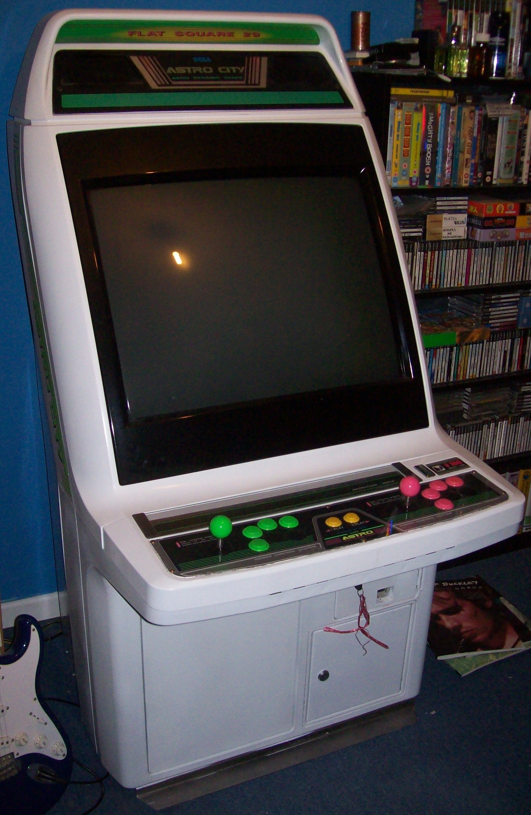
Sega's emblematic candy cab (1993): a compact seated cabinet, 29" screen, interchangeable control panel, JAMMA standard. A pillar of the "City" series and a reference for Japanese fighting/shmup play.
Identification
| Field | Value |
|---|---|
| Manufacturer | Sega |
| Year | 1993 |
| Type | Candy cab (compact seated cabinet) |
| Screen | CRT 29", Nanao MS8 (sometimes MS9), 15/24 kHz, rotatable (tate/yoko) |
| Controls | 2 players, interchangeable panel (typical config: 8-way stick + 6 buttons/player) |
| Power | 100 V (Japan), ~140 W |
| Accepted PCB format | JAMMA |
| Dimensions | 750 × 905 × 1445 mm (W×D×H) |
| Weight | 93 kg |
⚡ Connector & power
| Aspect | Value |
|---|---|
| PCB connector | JAMMA (56-pin edge) — no JVS (a 1993 cabinet) |
| Monitor sync | 15/24 kHz (Nanao MS8/MS9), no native 31 kHz |
| Power | 100 V AC (Japan) |
| Consumption | 140 W (manual: 消費電力 140W) |
| Dimensions | 750 × 905 × 1445 mm (W×D×H) |
| Weight | 93 kg |
Confirmed a second time, in English, by the 1993 Sega flyer
The Sega sales flyer archived here — front · spec strip — (© SEGA 1993, SD-3529) is bilingual and removes all ambiguity:
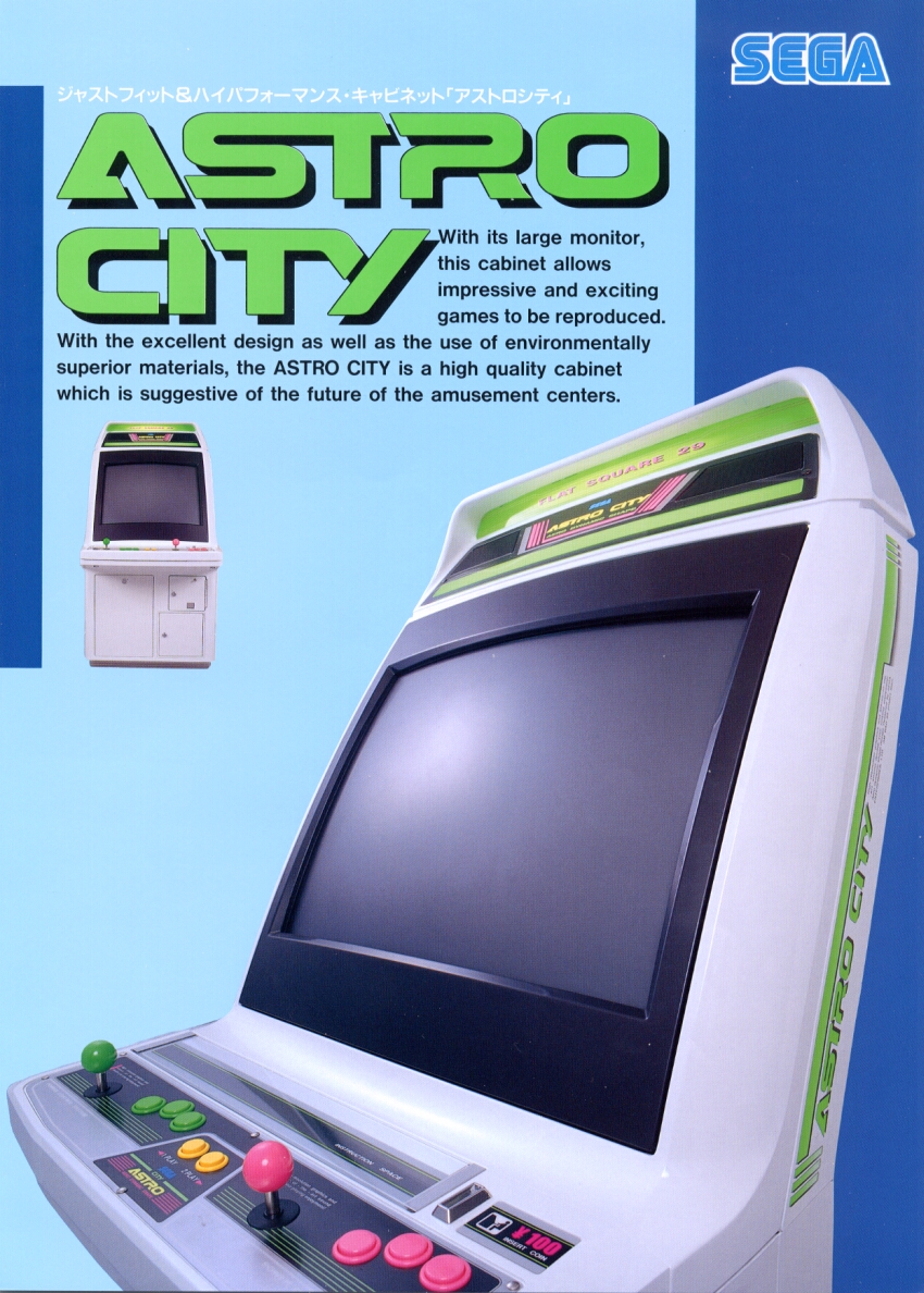
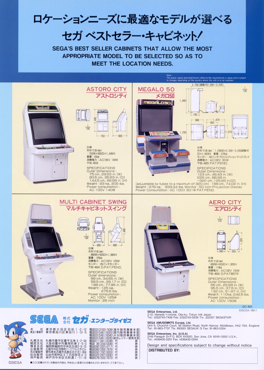
- 外形寸法(mm): 750W × 905D × 1,445H · 重量 93kg · 消費電力 AC100V 140W
- SPECIFICATIONS: 75 cm, 29.53 in. (W) · 90.5 cm, 35.63 in. (D) · 144.5 cm, 56.89 in. (H) · Weight 93 kg, 205 lbs · Power consumption AC 100V 140W
Sega spells out (W), (D) and (H). It is the clearest document in the corpus on the convention, and it matches the service manual word for word.
The same flyer carries the Aero City, the Megalo 50 and the Multi Cabinet Swing — see their pages.
Figure corrected against the Sega manual
The service manual states 所要面積: 750mm (幅) × 905mm (奥行) — that is 750 wide by 905 deep. The wiki had them the other way round; fixed here and on the New Astro City.
(Sources: Arcade Otaku; consumption/dimensions from the service manual.)
→ Detailed wiring: a JAMMA cabinet → see JAMMA wiring (56-pin pinout) and Control panels & buttons (Sega layout, interchangeable panel).
Anatomy
- Marquee (lit header) at the top.
- 29" CRT monitor on a rotatable frame (horizontal and vertical games).
- Interchangeable control panel (unscrews, harness to the board).
- Coin mech + service door.
- Sega PSU + JAMMA harness (+ kick harness per game).
- PCB tray (approx. 48 × 40 cm).
The "City" series
Sega's candy cab lineage: Aero City (predecessor) → Astro City (1993) → New Astro City (1995, Nanao MS9 monitor, improved speakers) → Blast City, Net City, Versus City (two back-to-back)… then the Naomi cabs.
Wiring
JAMMA connector (edge)
The cabinet is standard JAMMA (56 pins, finger-to-finger). Reference pinout (source: Arcade Otaku):
| Pin (solder / component) | Solder side | Component side |
|---|---|---|
| A / 1 | Ground (GND) | Ground (GND) |
| B / 2 | Ground (GND) | Ground (GND) |
| C / 3 | +5 V | +5 V |
| D / 4 | +5 V | +5 V |
| E / 5 | −5 V | −5 V |
| F / 6 | +12 V | +12 V |
| H / 7 | Key (notch) | Key (notch) |
| J / 8 | Counter 2 | Counter 1 |
| K / 9 | Lockout 2 | Lockout 1 |
| L / 10 | Speaker − | Speaker + |
| M / 11 | Audio ground | Audio + |
| N / 12 | Video Green | Video Red |
| P / 13 | Video Sync | Video Blue |
| R / 14 | Service | Video ground |
| S / 15 | Tilt | Test |
| T / 16 | Coin 2 | Coin 1 |
| U / 17 | Start 2 | Start 1 |
| V / 18 | P2 Up | P1 Up |
| W / 19 | P2 Down | P1 Down |
| X / 20 | P2 Left | P1 Left |
| Y / 21 | P2 Right | P1 Right |
| Z / 22 | P2 Button 1 | P1 Button 1 |
| a / 23 | P2 Button 2 | P1 Button 2 |
| b / 24 | P2 Button 3 | P1 Button 3 |
| c / 25 | (P2 Button 4) | (P1 Button 4) |
| d / 26 | (P2 Button 5) | (P1 Button 5) |
| e / 27 | Ground (GND) | Ground (GND) |
| f / 28 | Ground (GND) | Ground (GND) |
Buttons 4-6 & the key
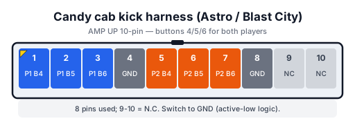
Buttons 4, 5, 6 (fighting games) generally go through a separate kick harness, not standard JAMMA (pins 25/26 in parentheses = not universal). Respect the key (pin 7): a reversed connection can fry the board.
Internal harness (cab side)
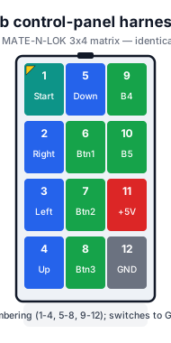
Connectors of the Astro City's internal harness (source: Arcade Otaku, Wiring Guide). The control panel handles 5 buttons + start per player.
Player 1 / Player 2 — 12 pins (same pinout for both):
| Pin | Function | Pin | Function |
|---|---|---|---|
| 1 | Start | 7 | Button 2 (SW2) |
| 2 | Right | 8 | Button 3 (SW3) |
| 3 | Left | 9 | Button 4 (SW4) |
| 4 | Up | 10 | Button 5 (SW5) |
| 5 | Down | 11 | +5 V |
| 6 | Button 1 (SW1) | 12 | GND |
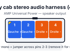
Audio — 4 pins, stereo:
| Pin | Function |
|---|---|
| 1 | Left + |
| 2 | Left − |
| 3 | Right + |
| 4 | Right − |
Kick harness (buttons 4/5/6, fighting games) — a separate AMP UP 10-pin harness:
Auxiliary: 10 pins (AUX 1 → 10). Earth: pin 1 = Earth, pin 2 = N/C.
Monitor connector (video + AC)
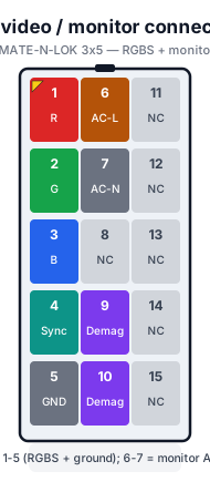
The monitor runs through a single 15-pin AMP connector (the one you unplug during disassembly): it carries the RGBS video signal (pins 1-5), the monitor AC (6-7) and the degauss (9-10):
Stereo sound
The Astro City can output stereo sound — notably better on games that support it (Konami shmups, CPS-2…). (Procedure after Arcade Otaku.)
Needed: a stereo amp (often already in the cab, otherwise cheap), a stereo game, and a loom for the amp input (the JVS conversion loom exposes RCA — handy for CPS-2, Gradius IV).
- Unplug the mono harness from the speakers: locate the two yellow AMP-Universal Power connectors at the bottom of the cab (the female has a loop between pins 2-3, red + blue wires). Unplug; let the female hang at the bottom. Don't cut it (useful for a future mono game).
- Plug the male into the PSU's yellow "Sound Out" connector → speakers connected to the amp.
- Volume to zero (otherwise you risk frying the speakers).
- Connect a loom to the amp's "Sound In" (red) input. A JVS loom for RCA / 3.5 mm jack outputs (CPS-2, Gradius IV). For a 4-pin JST (old Konami): pins 1-2 = left, 3-4 = right — check the game's manual.
- Connect the game (amp + JAMMA), volume to zero, power on, raise slowly (via the sound test if available).
Disassembly
(After thomj's "Strip Down Guide" / Arcade Otaku; applies to Astro City, Astro City II and New Astro City.)
- Remove the panel behind the fluorescent tube (Phillips screws; sometimes security Torx originally).
- At the front: open the control panel, remove the screws of the monitor bezel.
- Unplug the AMP connector feeding the bezel speakers.
- Remove the monitor bezel.
- Unplug the monitor: remove the 15-pin AMP connector; handle the remote board (unplug the ribbon, or unscrew the remote board in the CP).
- Remove the bolts holding the monitor to the chassis, take out the monitor.
- Separate the two halves of the base: screws at the rear bottom + on the sides (very stubborn).
JIS screws (classic trap)
The base screws are JIS (Japanese Industrial Standard), different from Phillips/Pozidriv — a Phillips screwdriver damages the head. Use a JIS bit + ratchet for torque. The most seized ones may need a screw extractor or grinding the head with a Dremel.
Internal boards
The main electronic sub-assemblies ("boards") — dedicated pages to create:
- 🖥️ Monitor: Nanao MS8 CRT chassis (sometimes MS9), 29", 15/24 kHz. → Repair: Nanao MS8 · Nanao MS9
- ⚡ Power block (Sega PSU) → Sega PSU repair.
- 🔗 Harness / distribution: JAMMA + kick harness + power + monitor.
Monitor adjustments (CRT)
- Geometry / convergence / purity via the chassis adjustments (mind the HV).
- Recap the monitor chassis if the image shakes / colours bleed.
- Degauss in case of colour patches.
High voltage
A CRT stores high voltage even when off. Discharge the tube before any work; don't work alone if untrained.
Common faults
| Symptom | Likely cause | Lead |
|---|---|---|
| Shaky image / bleeding colours | Monitor chassis capacitors | Recap the chassis |
| Colour patches on screen | Magnetised shadow mask | Degauss |
| No image but sound OK | Chassis / HV / monitor connectors | Chassis diagnosis |
| Game won't start | JAMMA harness / power / board contacts | Check power, reseat the board |
| Flaky buttons/stick | Worn microswitches, CP harness | Replace switches |
Procedure — a cabinet that will not start ✅
There is a CRT in this cabinet
The tube stays charged with the cabinet unplugged, and the anode cap is the first thing your hand meets behind the monitor. Discharge it, work with one hand, and never alone if you can help it. → CRT safety
This cabinet is documented as 100 V
It does not go straight onto a European socket. It needs a step-down transformer rated for the whole cabinet, monitor included — not a travel adapter. Feeding 230 V to a cabinet built for 100 V destroys the supply, and usually the monitor with it. → Cabinet power
What this adds
Ordered for a cabinet, not for a board: mains, low-voltage supply, loom, monitor, then the game. The overwhelming majority of "dead cabinets" are dead for a reason that has nothing to do with the PCB — which is why the board comes last here.
1. Mains, and what sits between it and the cabinet. The switch, the fuse or breaker, the isolation transformer if there is one. A cabinet that shows no sign of life at all is almost never electronic.
2. The low-voltage supply — measured under load. Aim for +5 V where power reaches the board — the JAMMA edge, or the JVS power connector, depending on the cabinet — with the game running, not on an idle bench. If the supply has an adjustment (most candy and JVS bricks do; the ATX brick in a PC cabinet does not), do it then and not before: set off-load, it leaves a board that boots and then glitches. With no adjustment the measurement still earns its keep — it tells you whether the supply holds. Check +12 V too, and −5 V if the board uses it: many do not, and an ATX brick does not provide it. → Cabinet power
3. The loom and the connector. Reseat, and check the grounds — a cabinet with a poor ground gives rolling picture, phantom inputs and noise, all at once, and none of it looks like a wiring fault. → Wiring
4. The monitor. This page describes the monitor as: CRT 29", Nanao MS8 (sometimes MS9), 15/24 kHz, rotatable (tate/yoko). CRT: no picture but the tube is warm and there is EHT — that is sync or video, not the tube. No EHT at all — chassis. A picture that shrinks, wanders or shifts colour is a chassis recap, and on these monitors that is a scheduled job, not a repair.
5. Scan rate — the mismatch that breaks nothing. If the board's rate is not one the monitor accepts, you get no picture and nothing is faulty. Check what this cabinet takes against what the board puts out before opening anything. → Modernising a cabinet
6. The control panel. Microswitches and the loom, in that order. A single dead direction is a switch; a whole player dead is the loom or its ground. → Control panels
7. Coin mech and sound. Last, because they hide nothing: a mech that no longer registers is usually dirty or misadjusted, and silence with a good picture points at the amplifier and its supply rails.
Maintenance & restoration
- Clean the plastic body ("curvy body"), marquee plexi and bezel.
- Refurbish the control panel (stickers, buttons, stick — often Sanwa/Seimitsu).
- Check the JAMMA harness, clean the contacts.
Common mods
- Native RGB: candy cabs already output clean RGB to the monitor.
- Supergun-friendly: connect isolated PCBs easily (JAMMA).
- LCD screen: LCD conversions exist (loses the CRT look).
- 31 kHz / tri-sync: the MS8/MS9 is 15/24 kHz; for 31 kHz (Naomi/VGA) you need a tri-sync monitor/chassis swap.
- → Modernising a cabinet: OSSC/GBS-Control, a Mean Well PSU, JVS conversion, I-PAC/J-PAC encoders, PC/FPGA in the cab.
Manuals & schematics (archived)
Locally archived copies (protection against dead links):
- 📘 Service manual — PDF
- 🔄 Monitor rotation (tate/yoko) — PDF
- 🏷️ Decals — Instruction Space · Warning
Photos / assets
(To add: full cabinet, rotatable monitor, control panel, JAMMA harness.)
Repair & maintenance
CRT monitor (discharge HV!) → CRT safety + Nanao MS8 / MS9 chassis · Sega candy PSU → PSU repair · recap → Recap.
Sources & attribution
Text (content synthesised/transcribed here, sources cited for attribution):
- Arcade Otaku Wiki — Sega Astro City (specs) — https://wiki.arcadeotaku.com/w/Sega_Astro_City
- Arcade Otaku Wiki — JAMMA (pinout) — https://wiki.arcadeotaku.com/w/JAMMA
- Arcade Otaku Wiki — Sega Astro City Wiring Guide (internal harness) — https://wiki.arcadeotaku.com/w/Sega_Astro_City_Wiring_Guide
- Arcade Otaku Wiki — Astro City Stereo Wiring — https://wiki.arcadeotaku.com/w/Astro_City_Stereo_Wiring
- NFG Games / GameSX — Sega City cabinet pinouts (AMP Universal MATE-N-LOK connector families, 12-pin matrix CP, 10-pin kick) — https://gamesx.com/wiki/doku.php?id=arcade:sega_city_cabinet_pinouts
- New Astro City Strip Down Guide by thomj (Arcade Otaku) — disassembly — https://wiki.arcadeotaku.com/w/New_Astro_City_Strip_Down_Guide
- Hard-Candy.com — Astro City — to reference — https://www.hard--candy.com/wiki/candy/Astro_City
Image:
-
astro-city.jpg— "The real dog god" (Wikimedia Commons), public domain — https://commons.wikimedia.org/wiki/File:Sega_astro_city_candy_cab.jpg

Review & corrections
How this space is used
Spotted a wrong value, an outdated procedure, a chip reference that does not match your board? Say so here, with what you observed (model, board revision, serial number, measurement). Every report is cross-checked against a source before anything changes — an unverifiable correction is published as “reported by …, not cross-checked” rather than silently applied.
Reading is open to everyone; posting requires signing in with Discord. Reports from the wiki's declared reviewers are handled first; anyone else's are read too, but go through a human before anything is changed.