Atari 5200
Atari console (1982), derived from the 400/800 micros. Remembered for its notoriously fragile analog joysticks (failing self-centering) — the most frequent repair.
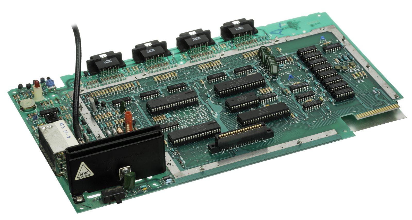
Identification
| Field | Value |
|---|---|
| Manufacturer | Atari |
| Release | 1982 |
| Base | Atari 400/800 micros |
| Media | Cartridge |
| Controllers | analog (self-centering) |
Architecture
| Block | Chip | Clock | Role |
|---|---|---|---|
| CPU | MOS 6502C | ~1.79 MHz | |
| Display | ANTIC (display-list processor) + GTIA | ANTIC reads a "display list" in RAM; the GTIA generates the colour | |
| Sound / I/O | POKEY | 4 voices + reading the analog controllers | |
| Memory | 16 KB RAM |
Architecture derived from the Atari 400/800 micros (same ANTIC/GTIA/POKEY) — hence its power, but fragile, non-self-centering analog controllers, a big weak point.
4-port vs 2-port versions
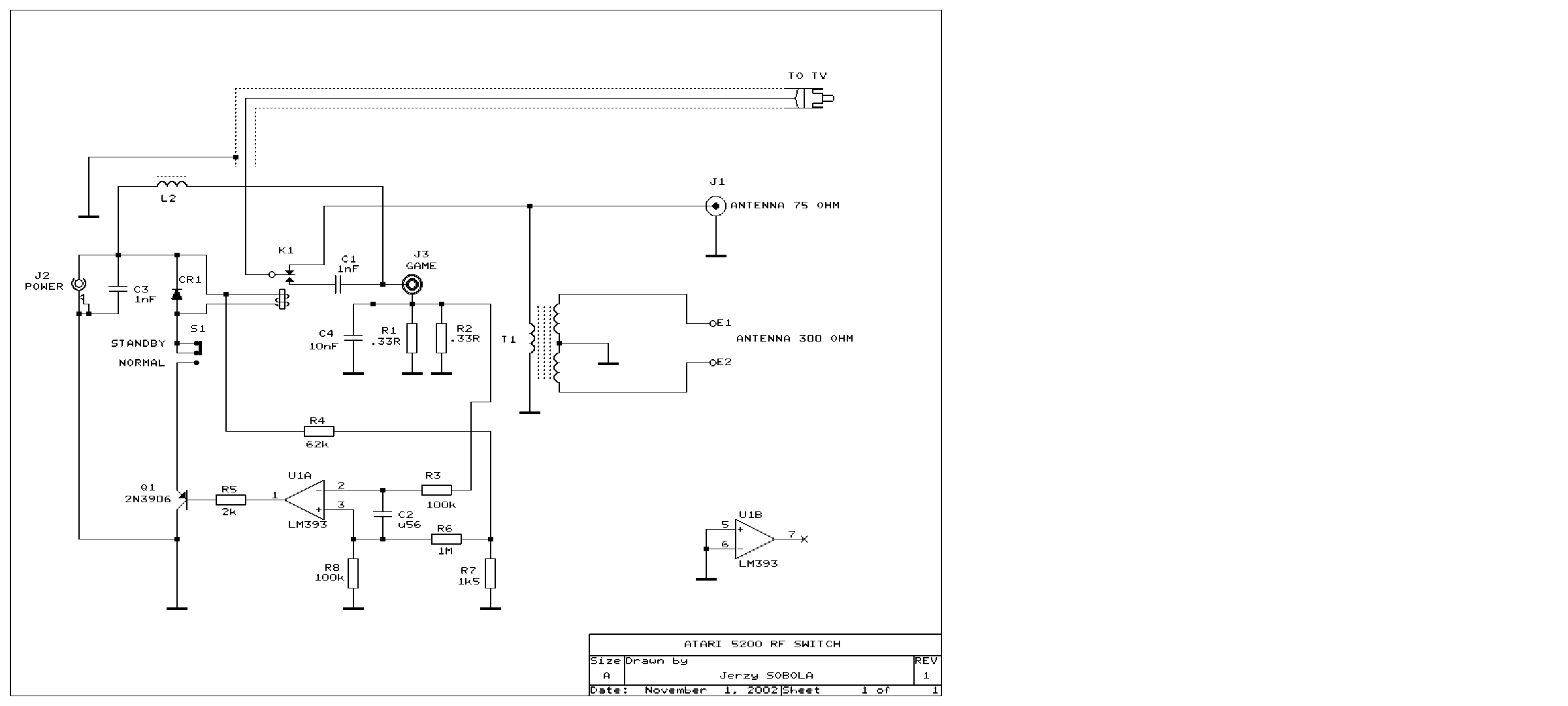
The first 5200 has 4 controller ports and an automatic TV switchbox (the RF signal passes through the console). The 2-port revision (1983) simplifies power/video and drops the auto switchbox for a standard cable — a detail that changes the video wiring when doing an AV mod.
Analog controllers (the weak spot)
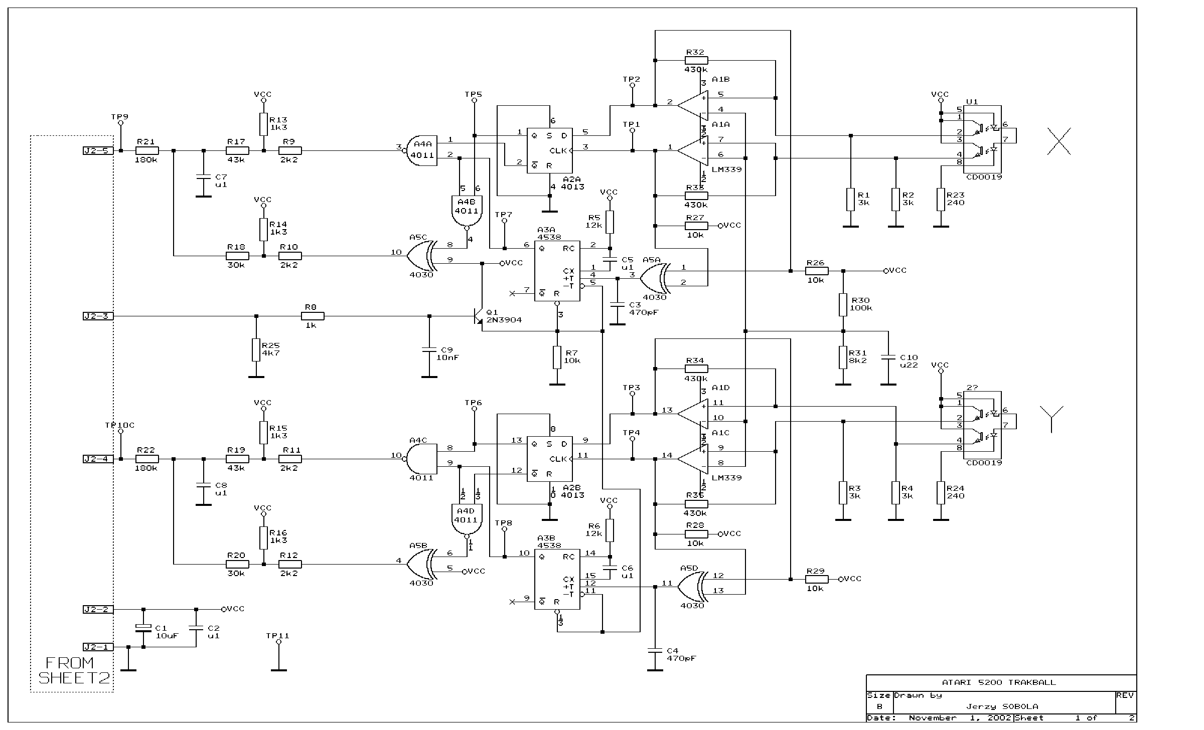
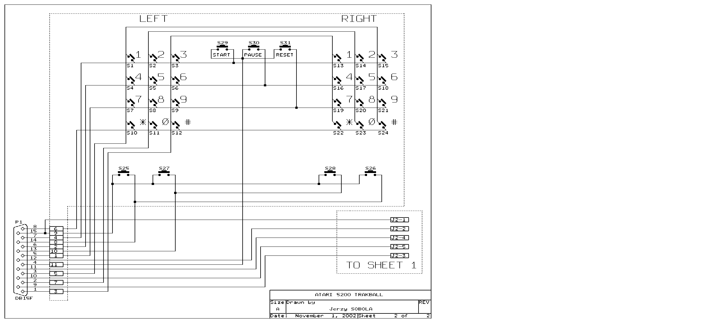
The non-self-centering analog sticks age very badly: cracked conductive membrane, tired return spring. Fixes: rebuild kits (repro membranes/springs), or the Masterplay adapter that lets you plug in a digital 2600-style joystick.
4-port or 2-port — the difference that matters ✅
Two console variants, three motherboard revisions.
4-port (1982-1983)
Four controller ports, the initial version from November 1982.
The big flaw: one cable and an unobtainable switchbox
The console uses a single cable combining audio, video AND power, and requires an unusual automatic switchbox. The consequence: a broken switchbox means no power AND no video output, with no easy replacement. It is the main risk factor when buying a 4-port. ✅ Fixable: see bypassing the switchbox.
- Shell: most 4-ports have a smooth-finish controller storage lid and front bezel — which are easily scratched and attract dust. These were replaced at some point in 1983 with textured matte pieces, which resist minor scratches but are fairly brittle and prone to breaking off.
- Manufacturing: mostly Sunnyvale, California (serial numbers with "SV") or El Paso, Texas ("EP"); some later ones in Taiwan.
⚠️ The VCS Cartridge Adaptor (CX55) does NOT work on most 4-ports
The 4-port's cartridge port is not properly wired to pass through the composite video and audio from the CX55, nor unregulated DC voltage to the adapter. A modification is required (Atari published a service bulletin on this).
The exception: some later 4-ports (mainly mid-1983) use a newer board, CA020108, which Atari called a "universal" board. These are the only 4-ports compatible with the CX55 out of the box, and are usually identified by an asterisk in the serial number. These boards also carry unused support circuitry footprints for a PAL GTIA chip — Atari planned a European release during 1983, quietly cancelled.
The 1985-1986 "Atari Corp." consoles: watch out for hybrids
Atari Corp. sold off the parts inventory inherited from Atari Inc. during 1985-86, assembling with whatever was at hand. Some 4-ports therefore exist in a 2-port bottom case but with an early-revision 4-port motherboard (CA018087) inside, plus a factory power jack modification filling the spare hole near the channel select switch. ⚠️ Because these use the original 4-port board, they are not CX55-compatible without modification. Atari Corp. also continued selling standard 4-ports with the automatic switchbox alongside them.
2-port (1983-1984)
A cost-reduced version from mid-1983: two controller ports and, crucially, an added power jack, which eliminates the need for the automatic switchbox. You can therefore use any standard RF switchbox, or a 75 ohm to F-type adapter, to connect the console straight to a TV. ✅ All 2-port models support the CX55.
All use the CA021374 board — similar to the CA020108 but lacking the footprints for the middle two controller ports and their supporting components; it still has the PAL GTIA footprints. Mostly manufactured in Taiwan, some in El Paso. The 5200 was officially discontinued in early 1984.
Some later 2-ports break three games — and it's repairable
These consoles carry a different BIOS, labelled C019156A, with an extra detection routine for PAL games that was never used. That change inadvertently broke compatibility with three titles:
- K-Razy Shoot-Out
- Mountain King
- Pitfall!
Repair: swap the BIOS chip with one from a 4-port or an early 2-port, or burn a 2716 EPROM with the earlier BIOS. (Source: ConsoleMods, CC-BY-SA.)
Bypassing the switchbox (4-port) ✅
On most 4-ports, the single permanently attached RF cable doubles as the power cable — hence the dependence on that specific switchbox, which is both a point of failure and a source of audio/video interference (everything travels down one wire).
The principle: the DC input power arriving through the RF/power cable passes through an inductor labelled L8, which then supplies the two 7805 voltage regulators. By removing L8 and injecting input voltage where L8 connects to the rest of the power circuit, the switchbox is completely bypassed — and ⚠️ the RF signal is completely unaffected.
The mistake that destroys the console
NEVER use an AC adapter intended for Atari 8-bit computers (400, 800…): they output AC voltage, which will damage the 5200.
Power supply to use: the kit uses the original PSU, but any 9-11.5 V, 2 A DC supply will work, centre positive, with a 5.5 mm outer / 2.5 mm inner diameter plug. You may also fit a 5.5 × 2.1 mm barrel jack wired for centre negative, so that a Model 1 Sega Genesis AC adapter can be used.
Materials: leaded solder, and either the 4-port power jack modification kit (available from Console5) or the individual parts — a 5.5 × 2.5 mm panel mount DC power jack, hookup wire, a 1N4001 diode or equivalent, a 0.1 µF ceramic capacitor, and a 47 µF or 4700 µF / 25 V electrolytic (optional). Tools: Phillips screwdriver, soldering iron, multimeter, flush cutters, wire stripper, desoldering braid or gun (optional).
Four notes that make the job easier
- The diode provides reverse-polarity protection: not necessary, but highly recommended.
- Removing the original 47 or 4700 µF filter capacitor is not necessary (it can be replaced if desired).
- No need to remove the metal RF shielding: all the power circuitry sits outside it.
- Leaving the attached video cable intact is recommended — you will use it to test the mod afterwards.
Disassembly starts with the seven screws underneath the console.
Common faults
| Symptom | Likely cause | Lead |
|---|---|---|
| Loose / off-center stick | Worn analog joystick | Controller repair kit (the most common) |
| Cartridge not read | Contacts | Cleaning |
| No image | Power, contacts, switchbox | Diagnosis |
| Neither image NOR power (4-port) | Automatic switchbox dead — it also carries the supply current | Switchbox bypass (remove L8 + DC jack) |
| K-Razy Shoot-Out, Mountain King or Pitfall! will not run | BIOS C019156A on some late 2-port units | Swap the BIOS chip, or burn a 2716 EPROM with the earlier BIOS |
| CX55 adapter does not work | 4-port cartridge port not wired for the CX55 | Modification required — except on the CA020108 board (asterisk on the serial number) |
| Console dead after plugging in the mains | An Atari 8-bit brick used (AC output) | ⚠️ Never a 400/800 brick on a 5200 |
Procedure — a dead console, step by step ✅
What this adds
Ordered for a console, not for an arcade board: what kills these is almost never the CPU. It is, in real order, the power supply, the capacitors, the drive or the cartridge slot, and only then the logic. → PCB diagnosis
1. The power supply. Two cases, depending on the machine. External brick: ⚠️ read the marking on the machine, next to the socket, and check the adapter against it — voltage and polarity. A centre-negative machine fed centre-positive loses its fuse, sometimes its regulator; do not trust a third-party label or a generic tip. Internal supply (the machine plugs straight into the wall): mains is inside the shell. Unplug, wait, and confirm the large capacitors are discharged before touching the board. Either way, measure under load: a failing supply holds its voltage until it is asked for current.
2. The fuse. Many of these machines have one right behind the socket — it is the part designed to die. Test it in continuity, out of circuit. A fuse that blows again is a short, not a fuse problem.
3. Capacitors. On most machines of this age this is the default suspect rather than a last resort — leaking SMD electrolytics eat the tracks underneath before they give any other sign. ⚠️ Not all of them are like that: some carry very few and are not recapped on principle. Read what this page says about it before reaching for the iron. → Recap
4. The cartridge connector. Cartridge contacts with isopropyl alcohol, never an abrasive eraser: it takes the gold plating off and the problem comes back worse. On the machine side, inspect the slot pins — splayed, bent or oxidised — and check continuity between slot and board.
5. Video output. Isolate the machine from the display: another cable, another TV, another input. A sizeable share of "dead consoles" are a dead cable, or a display that will not lock onto what this machine outputs — see the video section of this page for what that is.
6. Still nothing. Now, and only now, the logic: rails on the board, reset, clock, bus. → PCB diagnosis
Popular mods — what to buy, how
The controllers = the #1 problem
The 5200 analog controllers don't self-centre and age badly (conductive membrane, flaky fire buttons). It's THE recurring fault.
- Controllers 🟡: rebuild kits (membrane, contacts, buttons, springs — e.g. Best Electronics) or modern replacement controller PCBs; alternatively, adapters to use a modern controller.
- 4-port 🟠: the 4-port 5200 uses a finicky automatic switchbox → replace it (repro) or do the bypass mod (wire the A/V output directly) to make the picture reliable.
- AV/S-Video mod 🟠: tap a clean composite/S-Video output instead of RF (the 5200 has usable luma/chroma signals).
- Flashcart: AtariMax 5200 (SD multicart) — full library, plug-and-play 🟢.
- PSU recap + cartridge/controller contact cleaning.
Photos / assets
(To add: console, analog controller, board.)
Advanced repair
Analog controllers = a notorious weak point (conductive pads, pots) + cartridge contacts + recap. Methods: PCB fault-finding · Recap · Traces & vias.
Archived technical documentation ✅
Manufacturer documentation archived locally: schematics, block diagrams, expected voltages, parts lists. The reference when a symptom matches no known fault.
- Atari 5200 — PDF
Status
Manufacturer documents kept for preservation (machines out of production for decades), with no explicit licence — the same position as for the cabinet manuals already archived here.
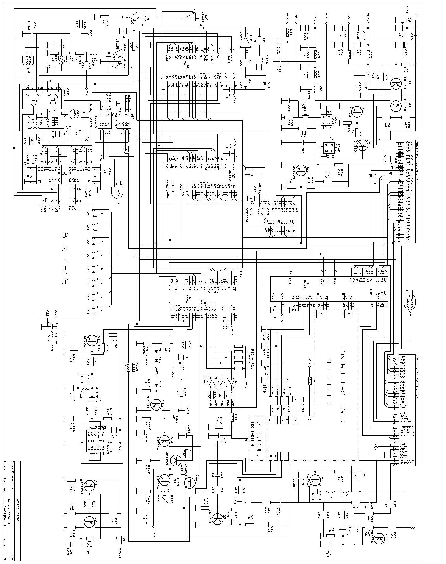
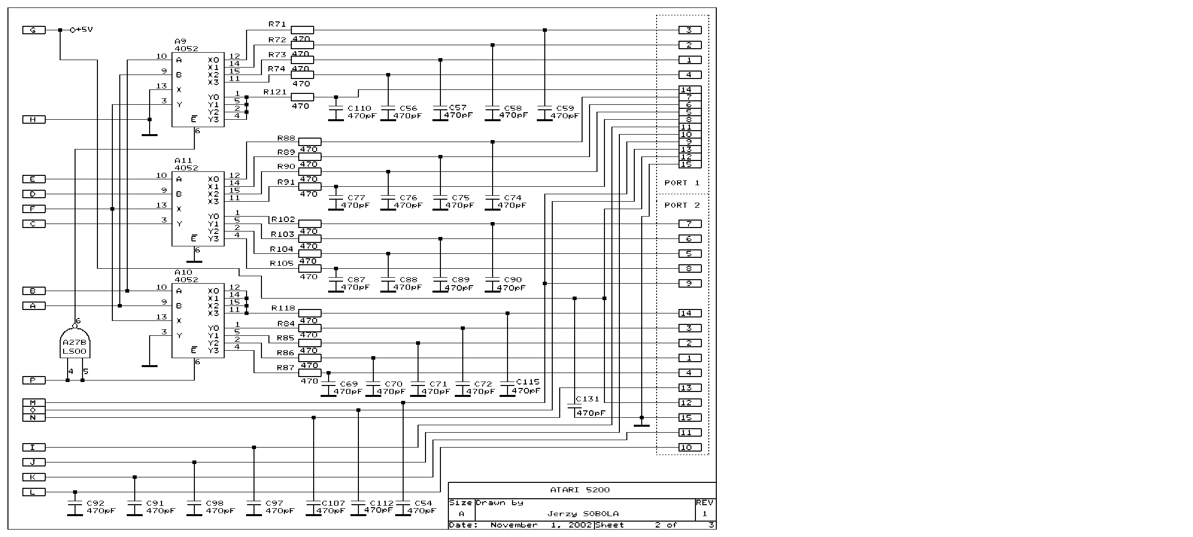
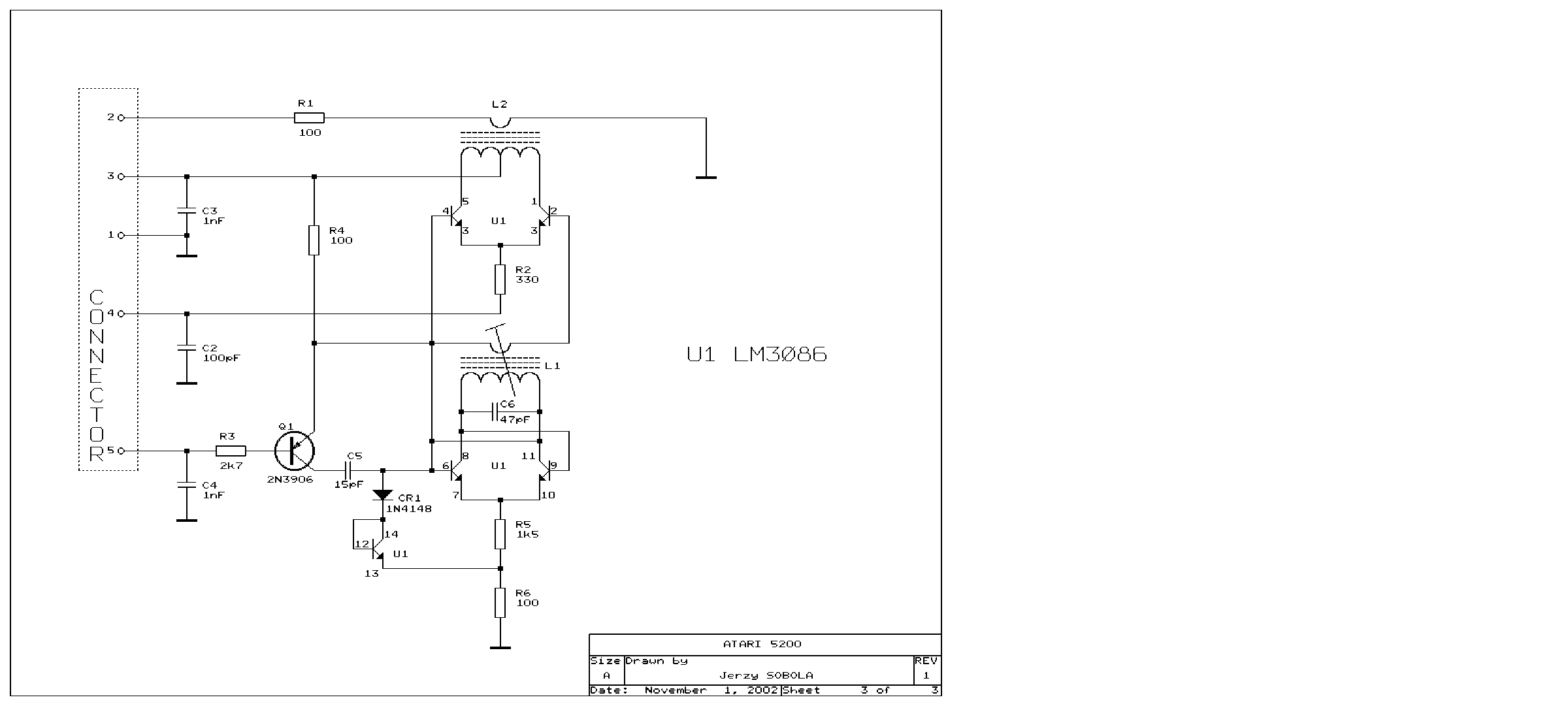
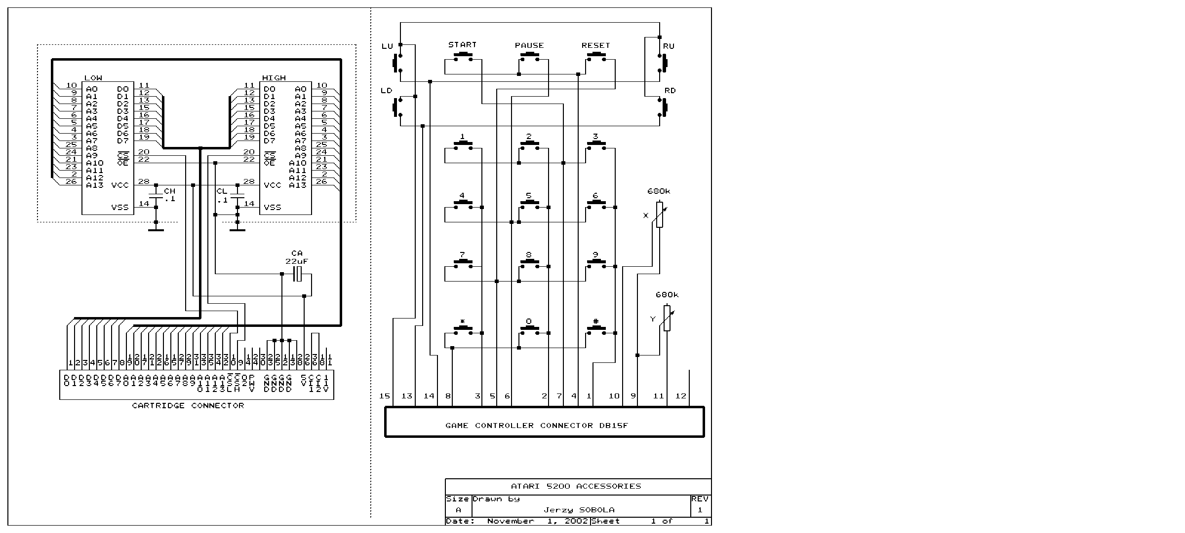
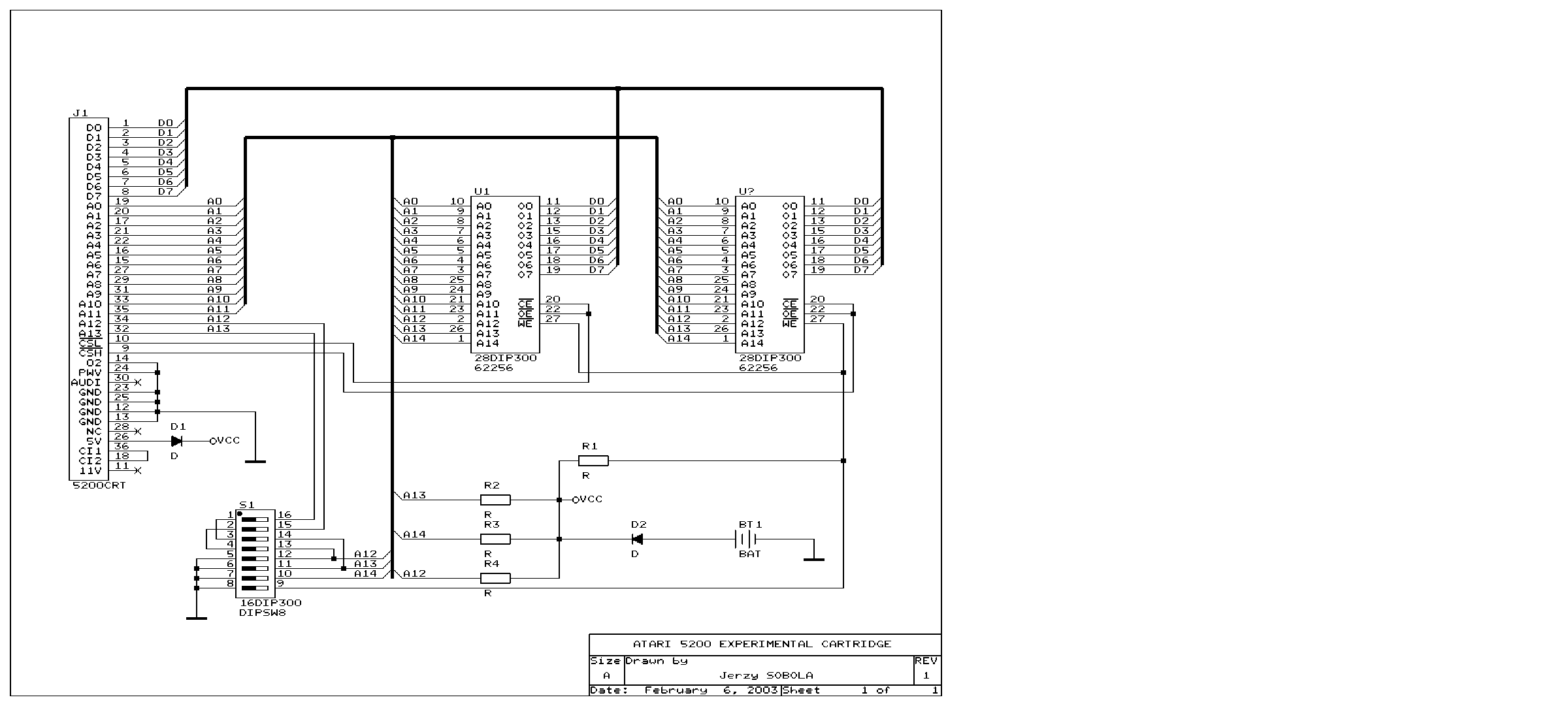
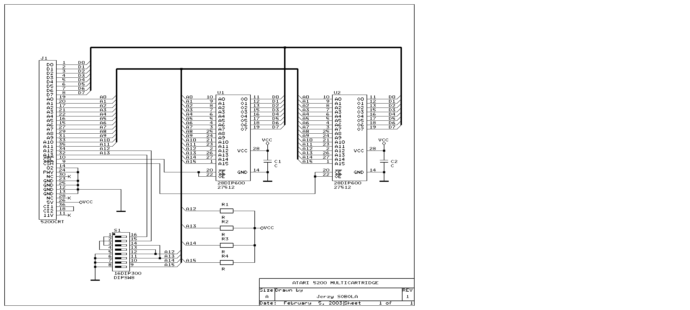
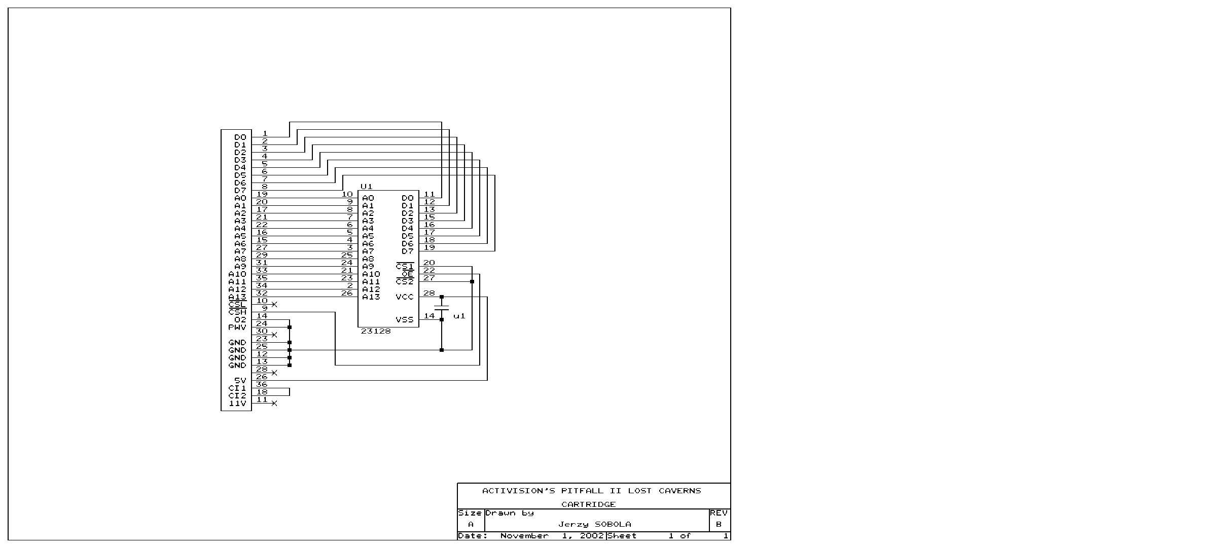
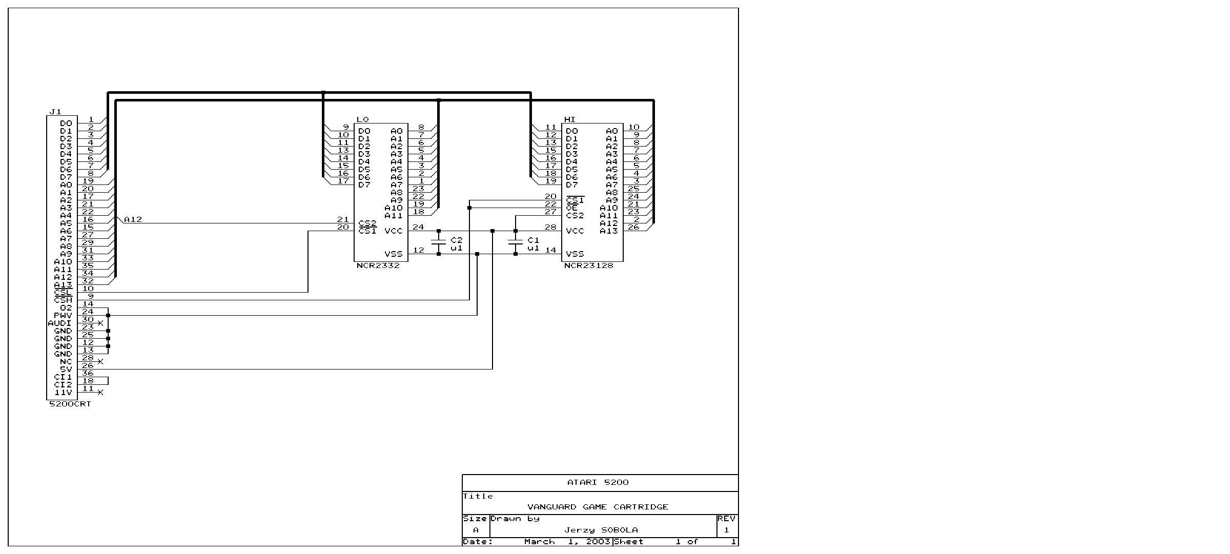
Atari 5200 schematics ✅
2-port and 4-port boards.
Credit
Schematics redrawn by Jerzy Sobola, reproduced here for preservation. These are not manufacturer documents: the drawing is his own work.
Sources & attribution
- ConsoleMods Wiki — Atari 5200 Model Differences — CC-BY-SA — 4-port vs 2-port, CA018087/CA020108/CA021374 boards, CX55 compatibility and the serial-number asterisk, SV/EP series, 1985-86 Atari Corp. hybrids, C019156A BIOS breaking 3 games — https://consolemods.org/wiki/Atari_5200:Atari_5200_Model_Differences
- ConsoleMods Wiki — Bypassing the Switchbox (4-port) — CC-BY-SA — principle (L8 inductor and the 7805 regulators), BOM (5.5 × 2.5 jack, 1N4001, 0.1 µF), 9-11.5 V 2 A supply spec, ⚠️ never use Atari 8-bit AC bricks — https://consolemods.org/wiki/Atari_5200:Bypassing_the_Switchbox_(4-port)
- Wikipedia — Atari 5200 — CC-BY-SA — https://en.wikipedia.org/wiki/Atari_5200
Image:
-
atari-5200-board.jpg— Evan-Amos, public domain — https://commons.wikimedia.org/wiki/File:Atari-5200-4-Port-Motherboard-BL.jpg

Review & corrections
How this space is used
Spotted a wrong value, an outdated procedure, a chip reference that does not match your board? Say so here, with what you observed (model, board revision, serial number, measurement). Every report is cross-checked against a source before anything changes — an unverifiable correction is published as “reported by …, not cross-checked” rather than silently applied.
Reading is open to everyone; posting requires signing in with Discord. Reports from the wiki's declared reviewers are handled first; anyone else's are read too, but go through a human before anything is changed.