Repair: Sega power block (candy cab)
The switch-mode PSU of Sega candy cabs (Astro City, New Astro City, Blast City…). It supplies the JAMMA rails: +5 V, +12 V, −5 V. Key points: the +5 V adjustment (to compensate for harness losses) and the recap as it ages.
Rails and measurement point ✅
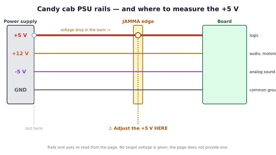
The +5 V is adjusted at the JAMMA edge, not at the terminal block
This is the trap on this supply. The +5 V carries the heavy current and drops in the loom: setting 5.00 V at the PSU terminals leaves the board below that.
An under-fed board does not stop cleanly — it crashes erratically, which reads as a logic fault. Measure and adjust at the JAMMA edge, with the board fitted and powered.
⚠️ This page gives no target voltage: it does not provide one, and an invented figure cooks a board.
Identification
| Field | Value |
|---|---|
| Type | Switch-mode power supply |
| Outputs | +5 V, +12 V, −5 V (JAMMA rails) |
| Cabinets | Astro City, New Astro City, Blast City, Net City… |
| Adjustment | +5 V pot (adjustable) |
The JAMMA rails & their role
| Rail | Use | Note |
|---|---|---|
| +5 V | logic (CPU, ROM, RAM, TTL) | the most critical: high current, sensitive to voltage drop → adjust at the JAMMA edge |
| +12 V | audio (amp), motors/feedback, some lighting | wider tolerance |
| −5 V | analog sound of some old PCBs (DAC/filters) | often the first stage to fail; unused on many games but essential to a few |
| GND | common ground | several JAMMA pins in parallel (current) |
100 V (Japan) mains input
Japanese candy cabs are wired for 100 V. On 230 V (France), you need a step-down transformer upstream — otherwise the PSU and monitor are out of spec. Check the PSU's input range before connecting.
The +5 V adjustment (important)
Adjust the +5 V AT THE JAMMA EDGE, not at the PSU
The harness drops voltage. Adjust the pot to read ~5.0-5.1 V at the JAMMA connector (where the PCB sees it), not at the PSU output. Too low → crashes/ corrupted graphics; too high (>5.25 V) → risk to the board. Measure under load (board connected).
Common faults
| Symptom | Likely cause | Lead |
|---|---|---|
| No output / can't start | Dried-out capacitors, protection, fuse | Recap; check the fuse |
| +5 V too low / unstable | Caps, pot, harness | Recap; adjust +5 V at the JAMMA edge |
| −5 V rail absent | −5 V stage (often the first to fail) | −5 V stage diagnosis |
| Noise / hum | Filter caps | Recap |
| Hot cut-outs | Cold joints, caps | Reflow + recap |
Procedure — working through the supply ✅
Mains inside the case
This is a switching supply: the primary side sits at mains potential and its bulk capacitor stays charged after unplugging. Discharge it and check before touching anything on that side.
1. Cold inspection. Swollen or leaking capacitors, cooked resistors, cracked solder around the heavy components and the output connector.
2. The fuse. Blows again = a short downstream. Find it first.
3. The rails, off the cabinet. Check each output on a dummy load rather than on a board: a supply that reads fine with nothing on it and collapses under load is the classic case, and testing it with a PCB connected risks the PCB.
4. Recap. See the recap section of this page. → Recap
5. Set +5 V under load — last. See the dedicated section on this page. Setting it off-load is what leaves a board that boots and then glitches. → Cabinet power
Recap
An aging switch-mode PSU = recap (primary and secondary filter caps, low ESR, 105 °C). Photograph before removal (polarity). The exact list depends on the PSU model — see the Arcade Otaku PSU guide (New Astro City): https://wiki.arcadeotaku.com/w/Sega_New_Astro_City
Mains
A switch-mode PSU handles mains and holds charged capacitors. Unplug, discharge, don't work live unless you know what you're doing.
Modernisation (alternative to recapping)
Many restorers replace the aging original PSU with a modern industrial block (like a MeanWell), more reliable and regulated:
- A modern +5 V / +12 V PSU (e.g. MeanWell RT-65B or a dual block) + a small −5 V converter (or a DC/DC) if the game needs it.
- Advantages: stable regulation, short-circuit/overvoltage protection, silence.
- Keeping the old recapped PSU as a backup remains a good preservation practice.
Don't forget the −5 V
Generic 5/12 V supplies have no −5 V. If a game depends on it (sound), plan a dedicated module, otherwise no sound / distorted sound.
Pitfalls
- Adjusting the +5 V unloaded (no board) → it drops once loaded.
- Forgetting the −5 V rail (some old games need it for sound).
Photos / assets
(To add: Sega PSU, +5 V pot, output connectors, caps area.)
The values, surveyed board by board ✅
ⓘ eleven Sun power supplies — this wiki now carries cap maps: location by location, the value and the voltage as a contributor read them off their own board. → eleven Sun power supplies
⚠️ This is not a manufacturer specification. A revision changes the list: read the can before you pull it, and where it disagrees with your board, your board is right. ⓘ A voltage the sheet does not give shows as —, never as a plausible number.
Sources & attribution
- Arcade Otaku Wiki — Sega New Astro City (PSUs guide) — https://wiki.arcadeotaku.com/w/Sega_New_Astro_City
- Console5 / community — candy cab PSU recap — to reference
Review & corrections
How this space is used
Spotted a wrong value, an outdated procedure, a chip reference that does not match your board? Say so here, with what you observed (model, board revision, serial number, measurement). Every report is cross-checked against a source before anything changes — an unverifiable correction is published as “reported by …, not cross-checked” rather than silently applied.
Reading is open to everyone; posting requires signing in with Discord. Reports from the wiki's declared reviewers are handled first; anyone else's are read too, but go through a human before anything is changed.