Super Nintendo / Super Famicom (SNES / SFC)
Nintendo's 16-bit console (1990). Super Famicom in Japan, Super Nintendo (SNES) in the West. Native RGB output, sound by Sony (Kutaragi), and revisions that matter a lot for video quality (the famous "1-CHIP").
Identification
| Field | Value |
|---|---|
| Manufacturer | Nintendo |
| Release | 1990 (JP), 1991 (NA), 1992 (EU) |
| Generation | 4th (16-bit) |
| Revisions | 2-chip (early) → 1CHIP → SNS-101 / SF Jr (1997-98) |
| Native video output | Composite + S-Video + RGB (multi-out) |
| Region / lockout | CIC chip (console + cartridge) + cartridge shape + 50/60 Hz + controller port (early PAL) |
| Media format | Cartridge |
Architecture
| Block | Component | Notes |
|---|---|---|
| CPU | Ricoh 5A22 (65C816 core) @ 3.58 MHz | Slows to 2.68 / 1.79 MHz depending on access |
| Video (PPU) | 2 PPU chips | 32,768-colour palette; 256×224, 512×448… |
| Sound | S-SMP: SPC700 (8-bit) + 16-bit S-DSP + 64 KB PSRAM | Designed by Sony (Ken Kutaragi) |
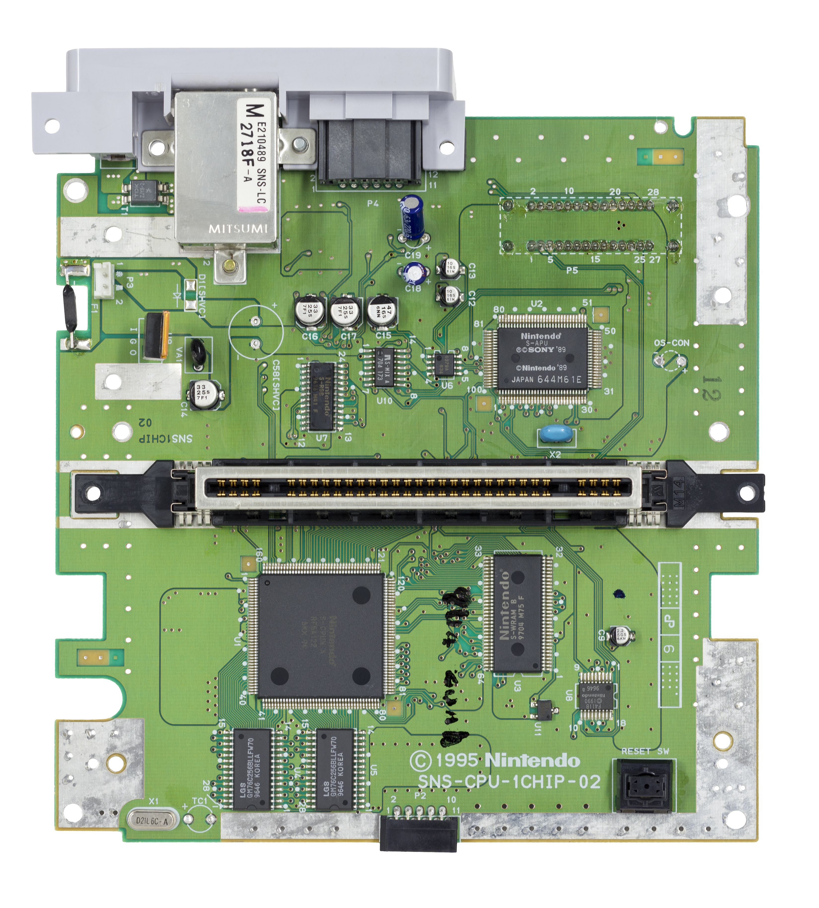
Revisions (the point that matters for video)
- 2-chip (early): the 2 separate PPUs. Slightly blurry RGB (stock).
- 1CHIP (SNS-CPU-1CHIP / SHVC-1CHIP boards): integration → sharper RGB image, the best stock. Highly sought after for RGB.
- SNS-101 (New-Style SNES) / SHVC-101 (SF Jr) (1997-98): economical redesign, 1CHIP base (excellent image) but a multi-out without stock S-Video/RGB (composite only) → needs an RGB mod to get RGB out.
Video outputs & quality
- Native RGB on the multi-out (except stock SNS-101/Jr).
- PPU1 (S-PPU1 5C77) + PPU2 (S-PPU2 5C78): modes 0-7 (Mode 7 = rotation/scaling), resolutions 256×224 and 512×448 (interlaced), pseudo-hires 512, transparency/color-math.
- Quality by revision: see Revisions above. In short: 2-chip slightly blurry, improved by an RGB amp; 1CHIP the stock reference.
Memory
- WRAM 128 KB (CPU) · VRAM 64 KB (PPU) · CGRAM (256×15-bit palette) · OAM 544 B (128 sprites) · ARAM 64 KB (audio, SPC700 side).
Enhancement chips (in the cartridges)
The SNES delegates power to coprocessors embedded in the cartridge — key to understanding the variety of games and modern recreations:
| Chip | Role | Games |
|---|---|---|
| Super FX (GSU-1/2) | 3D / polygons | Star Fox, Yoshi's Island, Doom |
| SA-1 | 65C816 @ ~10 MHz (accelerator) | Super Mario RPG, Kirby Super Star |
| DSP-1/2/3/4 | 3D math | Pilotwings, Super Mario Kart |
| Cx4 | trigonometry | Mega Man X2 / X3 |
| S-DD1 | real-time decompression | Star Ocean, Street Fighter Alpha 2 |
| SPC7110 | compression | Far East of Eden Zero |
| OBC1 / ST01x | misc | Metal Combat, Hayazashi Nidan… |
Cartridges: LoROM / HiROM
The cartridge's memory mapping comes mainly in LoROM (32 KB banks at
$8000-$FFFF) and HiROM (64 KB banks), plus ExHiROM for big games (Star
Ocean). The wrong mapping type = a game that won't boot — a key criterion for
repros/flashcarts.
Add-ons & peripherals
- Super Game Boy: a cartridge-adapter that runs Game Boy games on the SNES, with custom borders and palettes (some GB games ship special palettes/borders). SGB2 (Japan) adds a real link port and a corrected clock.
- Satellaview (BS-X, 1995, Japan): a satellite modem under the console, games and shows broadcast (St. GIGA), stored on an 8M memory cartridge. Content largely lost (ephemeral broadcasts) → a major preservation topic.
- Super Scope: a wireless optical bazooka (CRT only). SNES Mouse (Mario Paint). Super Multitap (up to 5 players, e.g. Super Bomberman).
Region & lockout
Four distinct locks — confusing them wastes diagnosis time:
- Cartridge shape (a physical lock): tabs inside the slot stop the cart from being inserted. Rounded shell in Japan, PAL regions and Korea; larger, blockier shell in North America and Brazil. Purely mechanical, unrelated to the electronics.
- CIC (electronic lockout) chip on both the console and cartridge → one region won't launch the other. F411 on every NTSC console (Japan/Korea and North America/Brazil), F413 on every PAL one. Corollary: a Super Famicom cart on a US SNES is blocked only by the shell shape, not by the CIC.
- NTSC 60 Hz vs PAL 50 Hz (speed/frequency). Some PAL games detect a console forced to 60 Hz and refuse to run.
- Controller port, on early PAL consoles only: their controller port board carries four extra ESD-protection diodes on the data latch and clock lines (pins 2 and 3) of the ports. PAL controllers compensate with pull-up resistors on those lines; NTSC SNES and Super Famicom controllers have none and therefore will not work on these consoles. The reverse holds: a PAL controller works on every region. ⚠️ This does not apply to PAL 1CHIP consoles, which use the Super Famicom's controller port board.
- Region-free (mod): cut the slot tabs (physical) + neutralise the CIC / add a region + 50/60 Hz switch; and, for an early PAL's controller port, bridge the four diodes.
Common faults
| Symptom | Likely cause | Lead |
|---|---|---|
| Cartridge not read / frozen screen | Cartridge connector oxidation | Cleaning (iso alcohol), no abrasive |
| Yellowed plastic | UV / ABS | Retrobright (with care) |
| Lost save (game) | Flat cartridge battery (CR2032/CR1616) | Replace the battery in the cartridge |
| No image | Power, multi-out, PPU | Check power / connectors |
| Absent / noisy sound | S-SMP / APU | Sound-stage diagnosis |
| Vertical bar down the centre of the picture | voltage drop during DRAM refresh — inadequate power filtering | See below |
The vertical bar — the most reported SNES fault, and it is fixable
A vertical bar runs permanently down the centre of the screen, most visible at power-on and in dark scenes (Super Metroid is the source's own example). It is neither the tube nor the cable: per ConsoleMods it comes from the voltage drop during DRAM refresh — that is, inadequate power filtering.
Four fixes, simplest first:
- Replace the 7805 regulator with a higher-current part such as the ST L78S05CV-DG. That is the main fix.
- In addition: replace the 1 µF SMD capacitor (C81) on the 78S05CV-DG's output circuit with a 22 µF.
- Variant without changing the regulator: add a 470 µF 16 V capacitor across the regulator (the one attached to the heat sink) — ⚠️ mind the polarity: the negative end (the striped side) goes to the centre pin. If that is not enough, try 1000 µF.
- An RGB bypass also works around it.
(The SNES has few electrolytic capacitors: it's not a "recap" console like the Mega Drive Model 2.)
Original service manual ✅
Manufacturer manual archived locally. It typically carries the schematics, the block diagram, the expected voltages and waveforms, the parts list and the disassembly procedures — the reference when a symptom matches no known fault.
Status
A manufacturer document with no explicit licence, kept for preservation (machine long out of production). Source: Internet Archive.
Step-by-step disassembly procedures ✅
6 procedures transcribed from the iFixit guides, with difficulty and estimated time.
| Procedure | Difficulty | Time |
|---|---|---|
| Disassembling Super Nintendo Cartridge | Easy | 5 minutes |
| Installing Super Nintendo Controller Port | Easy | 15 to 20 minutes |
| Installing Super Nintendo Eject Button | Moderate | 15 minutes |
| Replacing Super Nintendo Motherboard | Moderate | 15 to 30 minutes |
| Installing Super Nintendo Power Switch | Moderate | 15 minutes |
| Upper Case Removal | Moderate | — |
Disassembling Super Nintendo Cartridge
When games have been in storage or used for years on end, they need to get a good dose of TLC. In extreme cases you need to crack them open to get everything. It can be tense opening up a loved game in the fear that you'll destroy it. Alternatively, you can open up a game no one liked and make it into an innocuous enclosure for something else.
- On the bottom front corners of the cartridge you should see two screws using the 3.8mm "Gamebit" screwdriver bit. A 3.0U Spanner bit can also get them out.
- Once the screws are out, slide the front part of the plastic casing down to clear the tabs on the top of the case.
- The two halves of the case should open easily.
- At this point the game board and pins are freely accessible.
- Here you can fully clean the pin set and inspect for damage to the circuit board.
- Cleaning the pins is the easiest part; use a cotton swab and either a rich mixture isopropyl alcohol or Brasso. Other people swear by an eraser(the white kind), but it can lead to damage if you're not careful. Personally, Brasso works the best.
- At this point the game board and pins are freely accessible.
- Here you can fully clean the pin set and inspect for damage to the circuit board.
- Cleaning the pins is the easiest part; use a cotton swab and either a rich mixture isopropyl alcohol or Brasso. Other people swear by an eraser(the white kind), but it can lead to damage if you're not careful. Personally, Brasso works the best.
Installing Super Nintendo Controller Port
This guide will have you remove the upper case using a gamebit screwdriver and then in order to reveal the ribbon to the system from the controller port you will have to remove the reset button. This process will require only the gamebit.
- Lift the controller ports out of the housing, this should be done without much force. Take note of the location of the ribbon cable connection.
Installing Super Nintendo Eject Button
For this procedure you will have to first remove the upper case using the gamebit. Afterwards you will need to remove the metal pipe holding the reset button to the system. Be careful not to loose the spring when you remove the pipe. These steps will require only the gamebit.
- Lift the right side of the eject out of the housing.
Replacing Super Nintendo Motherboard
- Remove the two Phillips two 11.6mm screws that connect the front shield to the motherboard.
- Lift the front shield straight up to remove it from the motherboard.
- Remove the two silver Phillips two 15.6 mm screws on either side of the 62 pin connector.
- Remove the Phillips Two 11.8 mm screw located towards the rear of the SNES.
Installing Super Nintendo Power Switch
Shows how to remove the power switch connected to the motherboard. Steps can be followed in revers to install new power switch.
- Remove the two Phillips two 11.7 mm screws connecting the power switch to the motherboard.
Upper Case Removal
This guide will show you how remove the upper half of the Super Nintendo case.
- Remove the six 14.1 mm gamebit screws.
Source, licence and scope
iFixit guides, under Creative Commons BY-NC-SA — attribution, non-commercial, share-alike. Only the text is reproduced; the step photos stay on iFixit. ⚠️ These guides target the model named in the title: on another revision, the screws and the order of removal may differ.
Procedure — a dead console, step by step ✅
What this adds
Ordered for a console, not for an arcade board: what kills these is almost never the CPU. It is, in real order, the power supply, the capacitors, the drive or the cartridge slot, and only then the logic. → PCB diagnosis
1. The power supply. Two cases, depending on the machine. External brick: ⚠️ read the marking on the machine, next to the socket, and check the adapter against it — voltage and polarity. A centre-negative machine fed centre-positive loses its fuse, sometimes its regulator; do not trust a third-party label or a generic tip. Internal supply (the machine plugs straight into the wall): mains is inside the shell. Unplug, wait, and confirm the large capacitors are discharged before touching the board. Either way, measure under load: a failing supply holds its voltage until it is asked for current.
2. The fuse. Many of these machines have one right behind the socket — it is the part designed to die. Test it in continuity, out of circuit. A fuse that blows again is a short, not a fuse problem.
3. Capacitors. On most machines of this age this is the default suspect rather than a last resort — leaking SMD electrolytics eat the tracks underneath before they give any other sign. ⚠️ Not all of them are like that: some carry very few and are not recapped on principle. Read what this page says about it before reaching for the iron. → Recap
4. The cartridge connector. Cartridge contacts with isopropyl alcohol, never an abrasive eraser: it takes the gold plating off and the problem comes back worse. On the machine side, inspect the slot pins — splayed, bent or oxidised — and check continuity between slot and board.
5. Video output. Isolate the machine from the display: another cable, another TV, another input. A sizeable share of "dead consoles" are a dead cable, or a display that will not lock onto what this machine outputs — see the video section of this page for what that is.
6. Still nothing. Now, and only now, the logic: rails on the board, reset, clock, bus. → PCB diagnosis
Popular mods — what to buy, where, procedures
Common SNES tooling
4.5 mm gamebit screwdriver — ⚠️ 6 screws on the Model 1, 4 on the SNS-101 / SF Jr — + Phillips/JIS, temperature-controlled fine-tip iron, flux, razor blade/hook (to lift a pin), leaded solder, 28-30 AWG wire, drill + step bit. Procedures transcribed from ConsoleMods (CC-BY-SA). Soldering: 🟢 none · 🟡 · 🟠 · 🔴.
Video
- The SNES outputs RGB natively (multi-out). Quality depends on the board: 1CHIP
(
SNS-CPU-1CHIP-0x) gives the sharpest stock image → prefer it when buying. Boards predating the 1CHIP are softer and benefit from an RGB amp/bypass mod (THS7314/THS7374-type amp). Detail: SNES RGB bypass/amp page. - SNS-101 / SF Jr (1CHIP but no wired RGB output): a mod to get RGB out of the base — exact procedure below.
Procedure: get RGB out of an SNS-101 / SF Jr (transcribed from ConsoleMods, CC-BY-SA)
The SNS-101 already generates RGB internally (same S-RGB encoder as late Model 1 / 1CHIP boards) but it's not wired to the multi-out. Two options: wire the built-in S-RGB amp (the "3-wire" mod below), or fit a pre-assembled THS7374 amp board (beginner-recommended: 4 wires under the board).
DIY "S-RGB" mod (cheap) — also applies to the Super Famicom Jr. Materials: 26-30 AWG wire, 3× 75 Ω resistors (lowest tolerance), optional: 1× 1.74 kΩ 0805 (or 3× 1.2 kΩ) + 1× 220 nF or 470 nF 0805 cap. 4.5 mm gamebit bits.
-
Disassemble: 4 gamebit 4.5 mm screws underneath, then the 7 JIS screws holding the motherboard to the bottom shell.
⚠️ The two screws on each side of the cartridge port and the one on the multiout are LONGER than the rest. The source puts it bluntly: "Do not use these anywhere else or damage to the bottom shell may result." Refitting them elsewhere punches through the shell.
Then remove the RF shield and the 7805 heat sink (spiked-washer screws) to reach the S-RGB encoder = the 24-pin SMD chip directly behind the 7805.
-
Solder 4 wires to the S-RGB outputs (very fine tip, tin pin + wire, flux):
| Signal | S-RGB pin |
|---|---|
| Red | 20 |
| Green | 22 |
| Blue | 24 |
| Composite sync | 18 |
-
Route the wires to the underside, through the unused RF-modulator vias (clear them) for a clean install; refit the 7805 heat sink.
-
To the multi-out: a series 75 Ω resistor on pin 1 (red), pin 2 (green), pin 4 (blue); composite sync direct to pin 3 (TTL sync — not usable as-is on some devices; add a sync stripper if needed).
-
Picture too bright/washed out (common on 1CHIP): swap R3 (1.6 kΩ) for 1.74 kΩ 0805, or add 3× 1.2 kΩ pulldowns on the RGB lines. Ghosting/ringing: swap C11 for a 220–470 nF value.
Play imports — Region-free (disable the CIC)
The CIC (lockout chip) blocks out-of-region carts; neutralising it allows NTSC↔PAL (pair it with the 50/60 Hz switch below). Not needed to play Super Famicom on a US SNES: they're identical, only the cartridge shape blocks them → an adapter / removing the tabs.
Procedure: disable the CIC (transcribed from ConsoleMods, CC-BY-SA)
Find the CIC: an 18-pin SMD chip near the reset button — F411/F411A/F411B (NTSC) or F413/F413A/F413B (PAL); pin numbering is silkscreened next to it.
- CIC F41x / F41xA: lift pin 4 of the CIC. If you leave it lifted, tie that pin to ground (e.g. pin 9) — "highly recommended" in the source — to avoid damaging the CIC.
Cutting alone is not enough: without the switch you lose games
Games using the SA-1 chip detect a disabled CIC and refuse to boot. The source says so plainly: "A number of games, namely those which use the SA-1 expansion chip (i.e. Super Mario RPG, Kirby Super Star, etc.), can detect if the CIC has been disabled and will not boot unless the CIC is functioning normally. Because of this, it is highly recommended to wire up a SPDT switch to connect pin 4 to either 5V or ground instead of leaving it disconnected."
Those are exactly the games this page lists against the SA-1 chip. A CIC merely neutralised therefore leaves your console region-free and unable to run those titles, with no error message: it simply does not boot.
The switch is not an option, it is the correct way to do this mod: an SPDT toggling pin 4 between 5 V (lockout active) and ground (disabled).
- CIC revision B (late consoles): lift pin 4 of the CIC (U8) and pin 7 of U18 (marked CLK/S-CLK); to re-enable, wire a DPDT switch tying pin 4 (U8) → 5V and pin 7 (U18) → pin 56 of the cart slot.
Steps: open (6 gamebit screws), remove the board, generous flux on the pin, heat with the iron and gently lift with the razor/hook (patience — the pin and pad are fragile). No-lift alternative: commercial region-free CIC boards.
Play with an import controller — early PAL controller port
The mechanism — four ESD diodes, PAL controller pull-ups, the 1CHIP exception — is set out in the Region & lockout chapter. Here, only what to do.
Three fixes, any one is enough:
| Action | Soldering | |
|---|---|---|
| Use a PAL controller | none: it works on every region | 🟢 none |
| Modify the console | bridge the four diodes — procedure below | 🟡 |
| Modify the controller | fit R1/R2 at the "only-P" pads — ⚠️ not corroborated, see below | 🟡 |
⚠️ Check your console is affected first: PAL 1CHIP consoles are not. Opening a console that does not have the fault is an hour lost and a risk taken for nothing.
Procedure: making the controller port board region-free (transcribed from ConsoleMods, CC-BY-SA)
Materials: 4.5 mm gamebit screwdriver, soldering iron, hookup wire or cut-off component leads (from a resistor/capacitor), leaded solder, desoldering braid (optional), flush cutters, wire stripper.
-
Flip the console over and remove the six 4.5 mm gamebit screws. Take off the top case.
-
Remove the controller port PCB by carefully pulling the ribbon cable out of its connector on the motherboard.
-
With the board's solder side facing you, locate the solder joints of the four diodes. Bridge the two points of each diode with wire or a cut-off component lead.
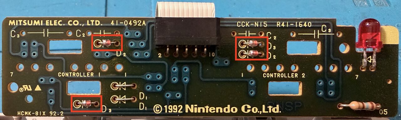
Mitsumi 41-0492A board from a PAL SNES: the four diodes to bridge are boxed in red — D2 and D3 on the controller 1 side, D2 and D3 on the controller 2 side. Click to enlarge. Photo: ApolloBoy, ConsoleMods Wiki, CC BY-SA 4.0. 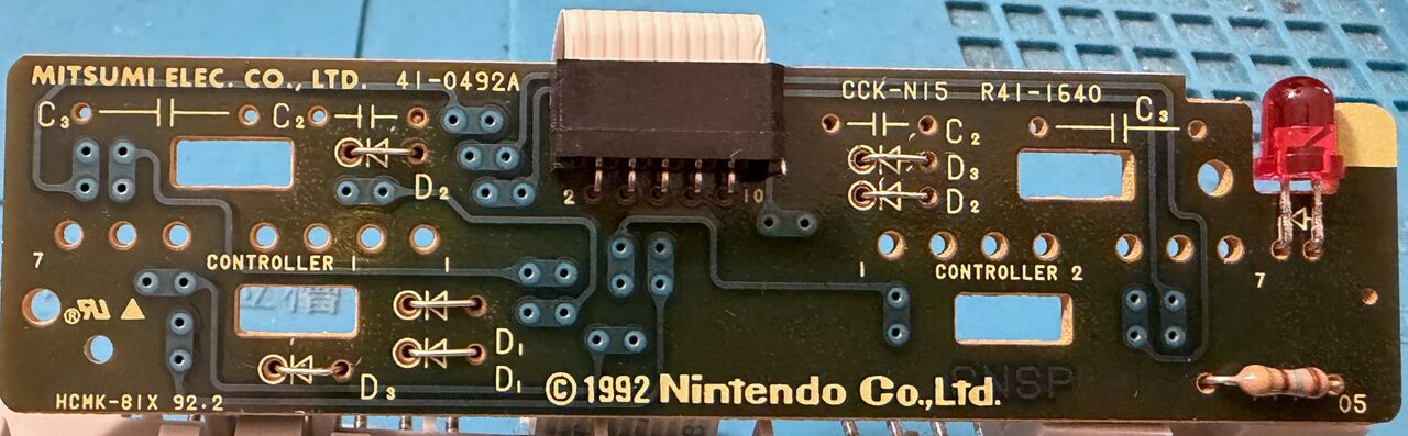
The same board once the diodes have been replaced with jumpers (step 4 variant). Photo: ApolloBoy, ConsoleMods Wiki, CC BY-SA 4.0. -
Variant: desolder the four diodes and replace them with jumpers. For more room, the board can be separated from the ports by desoldering the seven pins of each port, then pushing in the two plastic clips.
-
Reconnect the board, reassemble the console and test with an NTSC controller (US SNES or Super Famicom, either works). PAL controllers keep working normally.
Controller side (alternative, source GameSX/NFG): PAL controllers carry two resistors at the pads
silkscreened "only-P" — R1 = 1.2 kΩ (marked 122) and R2 = 3 kΩ (marked 302). Fitting them
to an NTSC controller makes it universal. Some controller PCB revisions lack those pads, in which
case you must solder elsewhere, and locating the points relies on the source's photos — not
reproduced here, therefore not corroborated: prefer the better-documented console-side mod above.
Speed — 50/60 Hz switch
On boards predating the 1CHIP (SHVC-CPU-01, SNSP-CPU-01/02…): force 50 or 60 Hz (⚠️ does not convert a
PAL into a true NTSC — it only affects speed/frequency).
Procedure: 50/60 Hz switch (transcribed from ConsoleMods, CC-BY-SA)
- Open (6 × 4.5 mm gamebit screws), remove the motherboard.
-
Find the two S-PPU chips near the controller-ribbon connector (pins silkscreened): locate PPU1 pin 24 and PPU2 pin 30.
-
Heat and gently lift PPU1-24 and PPU2-30 (very fragile pins) clear of the pad.
-
Tie PPU1-24 and PPU2-30 together with a wire, then a wire from PPU2-30 → the centre pin of an SPDT switch.
-
One outer pin of the switch → 5V via a 2.2 kΩ resistor (protects the PPUs), the other → GND (ground/output of the 5V regulator). 5V = 50 Hz, GND = 60 Hz.
-
Drill the shell with a step bit to mount the switch (the rear is discreet).
Play your library — flashcart
- FXPak Pro (formerly sd2snes, ikari_01 / Krikzz hardware) — a microSD FPGA cartridge,
plug-and-play 🟢: plays the whole library + homebrew, emulates the coprocessors (Super FX, SA-1,
DSP, S-DD1, CX4) and MSU-1. Where: Krikzz, Stone Age Gamer, RetroTowers… Open-source tool
archived locally (
files/tools/snes/).
Audio (optional)
- Digital Audio (SPDIF) Mod: clean optical digital audio output (dedicated ConsoleMods guide).
- Audio Balance Fix: corrects the slightly louder left channel on older consoles — exact points below.
Audio Balance Fix — the too-loud left channel (transcribed from ConsoleMods, CC-BY-SA)
Cause: the audio DAC NEC uPD6376 has two Vref pins (one per channel), each of which should have its own 47 µF cap to ground; Nintendo tied them to a single 47 µF → wrong impedances → left louder than right. Found by Ace (~2018-19).
Affected boards: SHVC-CPU-01, SNS-CPU-GPM-01/-02, SNSP-CPU-01/-02, SNS-CPU-RGB-01. Later boards use a single-Vref DAC → not affected.
Fix (materials: 1× 47 µF ≥10 V cap, iron, razor): isolate one of the two DAC Vref pins (pin 9 or 10), solder the + of a 47 µF to it, the − to ground.
-
SHVC-SOUND module (SHVC-CPU-01): lift pin 9 (the 9↔10 trace runs under the DAC). Ground = S-SMP pin 26 or the right side of C14 (verify with a multimeter). (Use the smallest cap possible — tight space.)
-
All other boards: cut the trace between pins 9 and 10 (isolates pin 10), + of the 47 µF on pin 10, − to ground (the − lead of the other Vref 47 µF next to the DAC, or DAC pin 5/12/14). Cut the cap leads as short as possible (anti-short).
Preservation & homebrew
- MSU-1: a homebrew extension (created by byuu) adding CD-quality streaming audio
- video — many "MSU-1" hacks swap in studio soundtracks, playable on sd2snes/FXPAK and in emulation.
- Emulation: very mature and accurate (bsnes/higan/ares, Snes9x, MAME).
Photos / assets
(To add: 2-chip vs 1CHIP board, multi-out, CIC area, cartridge + battery.)
Advanced repair
Cartridge contacts + recap (especially the APU audio); plastic yellowing aside. Methods: Recap · PCB fault-finding · Traces & vias.
Sources & attribution
- Wikipedia — Super Nintendo Entertainment System (CPU, PPU, sound, region, revisions) — CC-BY-SA — https://en.wikipedia.org/wiki/Super_Nintendo_Entertainment_System
- ConsoleMods — SNES: Disabling CIC (locating the 18-pin CIC, lifting pin 4, ground on pin 9, revision B with U18 pin 7 and a DPDT switch, and above all: SA-1 games will not boot without a working CIC, hence the "highly recommended" SPDT switch) — CC-BY-SA — https://consolemods.org/wiki/SNES:Disabling_CIC
- ConsoleMods — SNES: 50/60 Hz Switch (PPU1 pin 24, PPU2 pin 30, 2.2 kΩ, 5V = 50 Hz) — CC-BY-SA — https://consolemods.org/wiki/SNES:50/60_Hz_Switch
- ConsoleMods — SNES Jr DIY S-RGB Mod (S-RGB encoder pins 20/22/24/18 = R/G/B/CSYNC, 75 Ω to multi-out pins 1/2/4, sync pin 3, brightness R3 1.6k→1.74k, C11 220-470 nF) — CC-BY-SA — https://consolemods.org/wiki/SNES:SNES_Jr_DIY_S-RGB_Mod
- ConsoleMods — SNES: Vertical Line Fix (vertical bar = voltage drop during DRAM refresh; 7805 → L78S05CV-DG, C81 1 µF → 22 µF, 470 µF 16 V variant with the negative end on the centre pin, or RGB bypass) — CC-BY-SA — https://consolemods.org/wiki/SNES:Vertical_Line_Fix
- ConsoleMods — SNES: Audio Balance Fix (uPD6376 DAC, isolate Vref pin 9/10, 47 µF + to pin, − to ground via pins 5/12/14 or S-SMP pin 26) — CC-BY-SA — https://consolemods.org/wiki/SNES:Audio_Balance_Fix
- ConsoleMods — SNES: Making Controller Board Region-Free (4 ESD diodes on the data latch/clock lines, pins 2 and 3, of early PAL consoles; PAL controller pull-ups; bridging the diodes; not applicable to PAL 1CHIP) — CC-BY-SA — https://consolemods.org/wiki/SNES:Making_Controller_Board_Region-Free
- ConsoleMods — SNES: Region Information (F411 NTSC / F413 PAL, per-region cartridge shapes, PAL games and 60 Hz) — CC-BY-SA — https://consolemods.org/wiki/SNES:Region_Information
- GameSX / NFG — snes_con_region_fix (per-region controller compatibility table, "only-P" resistors R1 1.2 kΩ / R2 3 kΩ, console-side mod after SuperPlay) — https://gamesx.com/wiki/doku.php?id=controls:snes_con_region_fix
- RetroRGB — SNES RGB / 1CHIP / mods — https://www.retrorgb.com/snes.html
Image:
-
snes-1chip-board.jpg— Evan Amos (Vanamo Media), public domain — https://commons.wikimedia.org/wiki/File:Super-Nintendo-1Chip-Motherboard-Top-Flat.jpg

Review & corrections
How this space is used
Spotted a wrong value, an outdated procedure, a chip reference that does not match your board? Say so here, with what you observed (model, board revision, serial number, measurement). Every report is cross-checked against a source before anything changes — an unverifiable correction is published as “reported by …, not cross-checked” rather than silently applied.
Reading is open to everyone; posting requires signing in with Discord. Reports from the wiki's declared reviewers are handled first; anyone else's are read too, but go through a human before anything is changed.