Sega New Net City
The last candy cab in the City line (2005): an evolution of the Net City, designed JVS / network from the start, with a standard JVS panel and PSU and a chassis ready for 31 kHz (Naomi 2, Lindbergh-era).
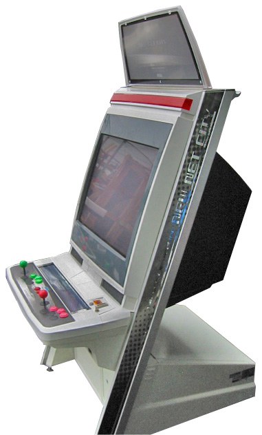
Identification
| Field | Value |
|---|---|
| Manufacturer | Sega |
| Year | 2005 |
| Type | Candy cab (last of the City line) |
| Screen | 29″ tri-sync CRT (15/24/31 kHz) |
| I/O | JVS (standard JVS panel) + network wiring |
| PCB format | JAMMA + JVS |
Technical notes
- The most modern City: built around the JVS standard (standard JVS panel and PSU), with factory LAN wiring like the Net City.
- Tri-sync: accepts 15/24/31 kHz → classic PCBs and 31 kHz systems (Naomi / Naomi 2).
- Flat multiscan monitor (Toshiba) 29″ 15/24/31 kHz, rotatable: Sega moved to the flat tube as curved tubes were being phased out.
- Network: supports non-Sega PCBs and connects to the VF.NET network (Virtua Fighter 4).
- Distinguished from the Net City by artwork details and full standardisation around JVS.
- Power: Sega candy brick → candy cab PSU.
⚡ Connector & power
| Aspect | Value |
|---|---|
| PCB connector | JAMMA + JVS (standard JVS panel + PSU) |
| Network | factory LAN wiring (networked games) |
| Monitor sync | tri-sync 15/24/31 kHz (29″ CRT) |
| Power | 100 V AC (Japan), Sega candy brick |
| Consumption | ≈ CRT candy cab (~140 W order of magnitude) — see the service manual |
(Sources: Arcade Otaku.)
Common faults
| Symptom | Likely cause | Lead |
|---|---|---|
| Unstable image (CRT) | tri-sync chassis, recap | Adjustments + recap (Nanao MS9) |
| Dead controls | JVS I/O / harness | JVS diagnosis |
| No power | candy brick | Check voltages at JVS/JAMMA |
Procedure — a cabinet that will not start ✅
There is a CRT in this cabinet
The tube stays charged with the cabinet unplugged, and the anode cap is the first thing your hand meets behind the monitor. Discharge it, work with one hand, and never alone if you can help it. → CRT safety
This cabinet is documented as 100 V
It does not go straight onto a European socket. It needs a step-down transformer rated for the whole cabinet, monitor included — not a travel adapter. Feeding 230 V to a cabinet built for 100 V destroys the supply, and usually the monitor with it. → Cabinet power
What this adds
Ordered for a cabinet, not for a board: mains, low-voltage supply, loom, monitor, then the game. The overwhelming majority of "dead cabinets" are dead for a reason that has nothing to do with the PCB — which is why the board comes last here.
1. Mains, and what sits between it and the cabinet. The switch, the fuse or breaker, the isolation transformer if there is one. A cabinet that shows no sign of life at all is almost never electronic.
2. The low-voltage supply — measured under load. Aim for +5 V where power reaches the board — the JAMMA edge, or the JVS power connector, depending on the cabinet — with the game running, not on an idle bench. If the supply has an adjustment (most candy and JVS bricks do; the ATX brick in a PC cabinet does not), do it then and not before: set off-load, it leaves a board that boots and then glitches. With no adjustment the measurement still earns its keep — it tells you whether the supply holds. Check +12 V too, and −5 V if the board uses it: many do not, and an ATX brick does not provide it. → Cabinet power
3. The loom and the connector. Reseat, and check the grounds — a cabinet with a poor ground gives rolling picture, phantom inputs and noise, all at once, and none of it looks like a wiring fault. Connector on this cabinet: JAMMA + JVS. → Wiring
4. The monitor. This page describes the monitor as: 29″ tri-sync CRT (15/24/31 kHz). CRT: no picture but the tube is warm and there is EHT — that is sync or video, not the tube. No EHT at all — chassis. A picture that shrinks, wanders or shifts colour is a chassis recap, and on these monitors that is a scheduled job, not a repair.
5. Scan rate — the mismatch that breaks nothing. If the board's rate is not one the monitor accepts, you get no picture and nothing is faulty. Check what this cabinet takes against what the board puts out before opening anything. → Modernising a cabinet
6. The control panel. Microswitches and the loom, in that order. A single dead direction is a switch; a whole player dead is the loom or its ground. → Control panels
7. Coin mech and sound. Last, because they hide nothing: a mech that no longer registers is usually dirty or misadjusted, and silence with a good picture points at the amplifier and its supply rails.
Repair
Identical to the other tri-sync candy cabs: recap + adjustments of the 29″ chassis (see Nanao MS9), Sega candy power.
Manuals (archived)
- 📘 VS setup guide (New Net City) (PDF)
- 📗 VS wiring diagram / pinout (PDF)
(Source: Arcade Otaku Wiki — scans by BlinG, archived locally for preservation.)
Photos / assets
(To add: New Net City, JVS panel, tri-sync chassis.)
Repair & maintenance
Modernise (video, PSU, JVS, upscaler, PC/FPGA) → Modernising a cabinet. CRT monitor (discharge HV!) → CRT safety + Nanao MS8 / MS9 chassis · Sega candy PSU → PSU repair · recap → Recap.
Sources & attribution
- Arcade Otaku Wiki — Sega New Net City (last City, 2005, standard JVS) — https://wiki.arcadeotaku.com/w/Sega_New_Net_City
- Internal pages: Net City · Astro City · candy cab PSU
Image:
-
new-net-city-borne.jpg— catalogue view, source Hard*Candy (⚠️ no licence statement anywhere on the site) — https://www.hard--candy.com/wiki/candy/NewNetCity
Review & corrections
How this space is used
Spotted a wrong value, an outdated procedure, a chip reference that does not match your board? Say so here, with what you observed (model, board revision, serial number, measurement). Every report is cross-checked against a source before anything changes — an unverifiable correction is published as “reported by …, not cross-checked” rather than silently applied.
Reading is open to everyone; posting requires signing in with Discord. Reports from the wiki's declared reviewers are handled first; anyone else's are read too, but go through a human before anything is changed.