Sony PlayStation 2 (PS2)
The best-selling console in history (2000). PS1 backward-compatible, DVD-based, Emotion Engine CPU. Preservation points: the optical drive (fat) and above all the softmod scene (FreeMcBoot) that opens USB/HDD/network with no hardware.
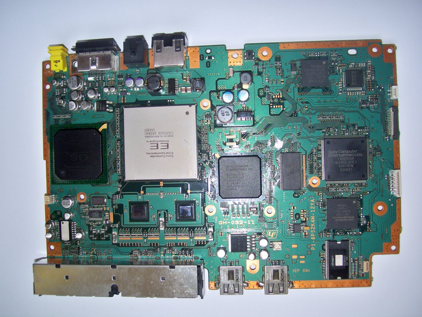
Identification
| Field | Value |
|---|---|
| Manufacturer | Sony |
| Release | 2000 |
| Generation | 6th |
| Models | Fat (SCPH-30000→50000, expansion bay) · Slim (70000+) |
| Backward-compat | PS1 |
| Video output | Composite, S-Video, RGB, Component (480p/1080i per game) |
| Media | DVD / CD |
Architecture
| Block | Chip | Clock | Role |
|---|---|---|---|
| CPU | Emotion Engine (MIPS R5900, 128-bit) | ~294/299 MHz | + 2 vector units VU0/VU1 (geometry), FPU |
| GPU | Graphics Synthesizer | ~147 MHz | 4 MB eDRAM at very high bandwidth (massive fillrate) |
| Sound | SPU2 | 48 voices ADPCM | |
| I/O | IOP (= the PS1's R3000 CPU) | handles I/O and PS1 backward-compat | |
| Memory | 32 MB RDRAM main + 4 MB eDRAM (GS) + 2 MB sound | ||
| Media | DVD-ROM (+ CD) | drive = weak point (see faults) |
PS1 backward-compatibility is hardware: the IOP is the PS1's processor. Slim models (SCPH-7000x+) integrate everything and a native network port.
Models & revisions (fat → slim)
| Generation | Models (SCPH) | Key point |
|---|---|---|
| Fat — early | 30000 / 3000x | PCMCIA expansion bay + i.Link; EE and GS separate |
| Fat — bay | 3500x / 3900x / 5000x / 500xx | rear expansion bay (Network Adaptor + 3.5″ IDE HDD) → OPL/HDD Loader |
| Slim | 70000 (2004) / 7500x / 7700x | very thin, built-in network, no bay or HDD; some "Deckard" boards |
| Slim — late | 90000 | integrated PSU, last revision, partly software PS1 backward-compat (Deckard) |
- The expansion bay (fat 3000x-5000x) takes the network adaptor + a 3.5″ IDE disk — the base of OPL/HDD Loader. The Slims have no bay (HDD loading via the MX4SIO/USB/SMB trick instead).
- Over the revisions, EE + GS end up merged (cost reduction, less heat) — late slims run cooler than early fats.
Controllers & accessories
- DualShock 2: like the DS1 but with pressure-sensitive analog buttons.
- Multitap (SCPH-10090): 4 players (note: incompatible with some late slims without an adapter).
- EyeToy (USB camera), Buzz! (quiz buzzers), SingStar (USB mics), Guitar Hero / Rock Band controllers, a DVD remote, wheels.
- Network Adaptor + HDD: online play (FFXI, SOCOM) and HDD Loader (fat). The official 40 GB disk shipped with Final Fantasy XI.
- A consumer DVD-Video player (a major 2000 selling point).
- PS2 Linux Kit (official): a keyboard/mouse/HDD/Linux kit — a collector's item.
- PSX (Japan): a PS2 + DVR recorder in an all-in-one unit.
Optical drive & "Disc Read Error"
The dual CD/DVD laser drive is the weak point of the fats:
- KHS-400B block (early) → KHS-400C. The laser gain pot and the rail/plastic gear wear → Disc Read Error (especially DVD, whose layer needs more power).
- Laser adjustment/replacement is possible, but the modern route is to load without a disc (FMCB + USB/HDD/network) → the drive is no longer used.
MechaCon & softmod compatibility
The system chip MechaCon handles power, the drive and security; its version determines which softmod methods work:
- On most models, FreeMcBoot (FMCB) installs on a memory card.
- On very late slims (recent MechaCon, e.g. SCPH-90000 v18+), classic FMCB won't take → use the matching FMCB 1.9x or the FreeDVDBoot exploit (via a booby-trapped DVD) / FreeHDBoot. Identify your MechaCon version before choosing.
Common faults
| Symptom | Likely cause | Lead |
|---|---|---|
| Disc Read Error (fat) | Worn laser / rail / gears | Adjust/replace the laser, or load without a disc (FMCB + USB/HDD) |
| Fat: DVD reading fails | Tired KHS-400 laser | Replace the laser |
| Slim: power | Internal PSU block | Diagnosis / replacement |
| Fan / overheating (fat) | Dust / paste | Cleaning |
Original service manual ✅
Manufacturer manual archived locally. It typically carries the schematics, the block diagram, the expected voltages and waveforms, the parts list and the disassembly procedures — the reference when a symptom matches no known fault.
- PS2 SCPH-30000 — service manual (6th ed.) — PDF
- PS2 SCPH-50000 — service manual (2nd ed.) — PDF
- PlayStation 2 — PDF
Status
A manufacturer document with no explicit licence, kept for preservation (machine long out of production). Source: Internet Archive.
Step-by-step disassembly procedures ✅
8 procedures transcribed from the iFixit guides, with difficulty and estimated time.
| Procedure | Difficulty | Time |
|---|---|---|
| Disassembling PlayStation 2 Top Cover | Easy | 10 to 15 minutes |
| Installing PlayStation 2 Disc Drive | Moderate | 60 to 75 minutes |
| Installing PlayStation 2 Fan | Moderate | 45 to 60 minutes |
| Installing PlayStation 2 Laser | Moderate | 20 to 30 minutes |
| Installing PlayStation 2 Power Board | Moderate | 45 to 60 minutes |
| Cleaning the lens | Easy | 15 to 20 minutes |
| PlayStation 2 Teardown | Moderate | No estimate |
| PlayStation 2 Teardown | — | — |
Disassembling PlayStation 2 Top Cover
Prerequisite for the lens cleaning and laser replacement.
- Flip the PlayStation 2 so that the bottom of the device is facing up.
- Using a metal spudger, pry the 8 flat screw covers out.
- Remove the following 8 screws:
- Four 55.4 mm Philips screws.
- Four 18 mm Phillips screws.
- Peel the warranty sticker next to the main power switch from the case.
Installing PlayStation 2 Disc Drive
In the need that you need to replace the entire disc drive, here's what you need to do. You may need to do a little eBay perusing first, but when you find that replacement, these steps will show you how to remove your old one.
- Underneath where the power supply once was is a transparent piece of plastic. This is the heat shield, and it can now be removed.
- It can be a bit stubborn, so it may take a little finessing to get it free.
- Now with the heat shield out of the way, you can see there are quite a few screws holding the rest in place.
- Remove the following screws securing the metal chassis to the logic board:
- Seven 5.8 mm Phillips silver screws.
- Two 7.4 mm Phillips gold screws.
- Unclip flaps, one on one side and two on the other, holding the disc drive together. The first two pictures display where the three flaps are. This is very tricky so take your time.
- Carefully begin to lift out the disc drive.
- Beware, there are ribbon cables still attached.
- Unclip flaps, one on one side and two on the other, holding the disc drive together. The first two pictures display where the three flaps are. This is very tricky so take your time.
- Carefully begin to lift out the disc drive.
- Beware, there are ribbon cables still attached.
Installing PlayStation 2 Fan
If your PS2 is overheating it may be time to replace the fan. If you have a faulty power switch you can change it with this guide too.
- Underneath where the power supply once was is a transparent piece of plastic. This is the heat shield, and it can now be removed.
- It can be a bit stubborn, so it may take a little finessing to get it free.
- We can now remove the fan and main power switch assembly.
- Remove the small white piece of tape that holds the wire connected to the fan.
- Unplug the wire from the logic board.
- The fan and switch are now free from the rest of the PS2. Simply remove it by pulling it out the bottom.
- The fan simply slides out of the top along its track.
Installing PlayStation 2 Laser
Replacing the laser requires you to have or purchase a new laser.
- Remove the four 6.4 mm Phillips screws which hold the lid of the disc drive on.
- Remove the lid.
- Remove the four 6.4 mm Phillips screws which hold the lid of the disc drive on.
- Remove the lid.
Installing PlayStation 2 Power Board
Prerequisite for removing the fan, power switch, and the disc drive.
- Remove the two 6.4 mm Phillips black screws holding the disc drive in place.
- Remove the whole disc drive by carefully tilting the lid and sliding out.
- Remove two 14.6 mm Phillips head gold screws to remove controller port.
- Gently lift out the controller port.
- Disconnect the ribbon cable from the controller port.
- Remove two 14.6 mm Phillips gold screws holding the fan.
- If you utilize your expansion bay for its intended purpose, make sure you remove the component now.
- Remove the cover for the expansion bay.
- Pull the innards out and away from the bottom cover.
- Now that all of that bulky plastic is out of the way, we can get to the fun stuff - electronics!
- Let's begin by removing the four 7.6 mm Phillips head gold screws holding on the power supply board.
- If you utilize your expansion bay for its intended purpose, make sure you remove the component now.
- Remove the cover for the expansion bay.
- Pull the innards out and away from the bottom cover.
- Now that all of that bulky plastic is out of the way, we can get to the fun stuff - electronics!
- Let's begin by removing the four 7.6 mm Phillips head gold screws holding on the power supply board.
Cleaning the lens
The "Disc Read Error" is one of the most common, and possibly the most frustrating error you might encounter. The problem occurs because dust or debris has accumulated on the lens. Luckily, it is easy to fix and takes a few short and simple steps!
- Clean the lens with a Q-tip dampened with rubbing alcohol.
PlayStation 2 Teardown
First, I would like to apologize for my poor English, I am from Brazil, but I love this site, especially because I have loved to disassemble electronic things since I was a kid. My mother always freaks out, but I always assemble everything back. Sometimes I even fix some things. I'm writing this teardown to try to win the PSP GO or the PS3 slim, so please look with care, it was made with care. (editor’s note: WOOOOW This article is outdated. I hope you won your PSP GO or PS3 Slim. In this teardown, I will show how to disassemble a Sony Playstation 2. I was already planning to disassemble it to clean it and fix a small issue. Later in the repair guide, I will show how to fix a small problem I had. I sent it to a technician because the rumble effect was no longer working. He says that there was a problem in the motherboard and he needs to change it entirely, but the model is a SCPH 39001. It’s an old model. In fact, it was one of the first in the market. He says that the price to fix it was expensive and that it’s better to buy a PS2 Slim to replace mine. I remember when a bought my PS2. It cost more than R$800, almost US$400. I decided to stay with it anyway, and despite the problem, I even bought an ethernet adapter to continue playing it. Later, talking with some friends, I found out that there is a fuse that controls the rumble effect and all that I needed to do was change it. I found out that the fuses in the mainboard are very small and fixed in the main board. It’s almost impossible to change them. The same friend gave me a tip that I can use a glass fuse and take the internal wire to use in the main board. I decided to try it and it works perfectly. So, let’s start the teardown. Enjoy!
- Here we have the system console fully assembled.
- The USB Ports.
- The S400 ports
- The Optical Drive
- The reset button
- The eject button
- These are the only tools that we will need. 4 screwdrivers and a tweezer.
- In the next photo we can see the console, the joystick, the wires and a memory card.
- In the Back, in this case we have a Ethernet adapter, to play online and to use with a Hdd.
- And the cooler,
- The power switch
- The AC in.
- The Av out
- And the digital output (optical)
- Lets start the teardown. At first we use a Flathead screwdriver to remove the ethernet adapter.
- Remove these 2 screws with a Flathead screwdriver.
- And is quite simple to pull.
- (Please note that not all PS2s come with a ethernet adapter or hard drive installed.)
- This is the expansion bay, where the hard drive goes.
- Turn the console upside down.
- Using a small Flathead screwdriver, remove the screw protections. In this model, we have 8 of them.
- Under the protection, suprise! a screw!
- Remove all eight (8) screws with your Philips "0" screwdriver.
- Yes, hard work!
- Put the console in the normal horizontal position, and pull the top cover from back to front.
- This model has a flat cable to the reset and eject button. Take extreme caution to not destroy it.
- Remove the button structure just pulling with a small Flathead screwdriver.
- The button structure comes out of the case. It has some tape to prevent a new destruction. Yes, I already destroyed this flat cable.
- Remove the two screws with a Philips "0" screwdriver to deatach the controller port.
- Here we remove the screws from the cooler and the main power switch
- Pull the fan up carefully so you don't break the wire.
- Pull up the fan mount.
- The power cable goes further inside the case. It's better to remove it in a future step.
- The fan wire also goes more inside the case. Take extreme care not to destroy it because it is very small.
- Lets turn the console upside down again, with caution because the pieces are locked, and just in the next step we can remove them.
- Lets remove the bottom case.
- This is the power source board. remove the 4 screws where I marked in blue.
- Looking from the back, pull up the board, releasing from the pins of the main board.
- Finally you can remove the power switch.
- And this is the power source board.
- When working on the power supply, be very careful not to touch the capacitor leads or any exposed solder joints on the back of the power supply. Only handle the board by the edges.
- Now we remove the expansion bay grid.
- And now is the time to remove the fan wire from the main board, using a precision tweezer. But.. I can't, it is simply stuck. I already removed this ealier, but now is harder, so I will try later, in the end of the teardown.
- Remove the isolation cover from the metal case.
- Remove the small screws using a thin crosshead screwdriver.
- And release the metal case from the DVD player, as indicated, using a small flat screwdriver
- Now you can remove the metal case and find the main board.
- Look, the flat cables! Now is the time to remove them. Be gentle please.
- There are 2 more and the DVD player is free.
- Now you can turn upside down again, and remove the metal protection.
- This is the other side of the main board.
- Well, the try to remove the cooler wire was a total failure.
- The plug is made to deatach, but it is old. The plug had turned into one piece, and broke the soldering.
- Well, I'll find a way to fix it. I always do =)
- This is the end of the teardown.
- From top, from the left: Ethernet adapter, Ps2 case, Hdd, Cooler, Cooler grid, bottom metal cover protection, screws protectors, screws, Controller board, Power swtich, Power source board, Plastic cover to isolate the power source board, top metal cover, DVD Drive, Expansion Bay cover, main board, reset/eject structure.
PlayStation 2 Teardown
- Flip the Playstation 2 (PS2) so that the bottom of the device is facing up. Using a metal splunger pry the 8 flat screw covers out. Remove the following 8 screws: Four 55.4mm Philips head screws. Four 18mm Phillips head screws.
- Peel away the sticker that says "Warranty void if this seal on the Playstation2 console is removed." It is right next to the main power switch. Please note removing this sticker will void your warranty but if it is the old fatty, it propably isnt anyway
- Flip the PS2 back over and remove the top cover, prying the half closer to the power switch first and rocking the whole thing towards the front. Carefully remove the cord that attaches the two halves by unclipping the power cord assembly from the case in the lid.
- Remove the four 6.4mm Phillips head screws which hold the lid of the disc drive on. Remove the lid.
- Remove the two 6.4mm #00 Phillips head black screws holding the disc drive in place. Remove the whole disc drive by carefully tilting the lid and sliding out.
- Remove two 14.6mm Phillips head gold screws to remove controller port.
- Gently lift out the controller port. Remove the ribbon cable.
- Remove two 14.6mm Phillips head gold screws holding the fan.
- Remove the cover for the Expansion Bay. If you utilize your expansion bay for its intended purpose, make sure you remove the component now. Pull the inards out and away from the bottom cover. Now that all of that bulky plastic is out of the way, we can get to the fun stuff - electronics! Let's begin by removing the four 7.6mm Phillips head gold screws holding on the power supply board.
- With the screws out of the way, the metal case that houses the expansion bay will lift off with ease. There is one cable that is clipped onto the power board. It is located next to the main power switch. Carefully begin lifting the power board. You can now see the clip holding the power board in place. Unsnap the clip, and the board is free from the unit.
- Underneath where the power supply once was is a transparent piece of plastic. This is the heat shield, and it can now be removed. It can be a bit stubborn, so it may take a little finessing to get it free.
- Now with the heat shield out of the way, you can see there are quite a few screws holding the rest in place. First, remove the seven 5.8mm Phillips head silver screws. Next, take out the two 7.4mm Phillips head gold screws.
- We can now remove the fan and main power switch assembly. Remove the small white piece of tape that holds the wire connected to the fan. Unplug the wire from the logic board. The fan and switch are now free from the rest of the PS2. Simply remove it by pulling it out the bottom.
- Unclip flaps, one on one side and two on the other, holding the disc drive together. The first two pictures display where the three flaps are. This is very tricky so take your time. Carefully begin to lift out the disc drive. Beware, there are ribbon cables still attached.
- There are four ribbon cables attached to the disc drive. Be careful not to rip any of them! Remove the three blue ribbon cables and one little orange cable by gently pulling on the blue plastic strips. Carefully remove the orange ribbon cable from the laser by gently pulling on the white plastic strip.
- After the disc drive has been completely removed flip it over. Gently lift off the metal cooling fins. All that remains in view should be the logic board.
Source, licence and scope
iFixit guides, under Creative Commons BY-NC-SA — attribution, non-commercial, share-alike. Only the text is reproduced; the step photos stay on iFixit. ⚠️ These guides target the model named in the title: on another revision, the screws and the order of removal may differ.
Procedure — a dead console, step by step ✅
What this adds
Ordered for a console, not for an arcade board: what kills these is almost never the CPU. It is, in real order, the power supply, the capacitors, the drive or the cartridge slot, and only then the logic. → PCB diagnosis
1. The power supply. Two cases, depending on the machine. External brick: ⚠️ read the marking on the machine, next to the socket, and check the adapter against it — voltage and polarity. A centre-negative machine fed centre-positive loses its fuse, sometimes its regulator; do not trust a third-party label or a generic tip. Internal supply (the machine plugs straight into the wall): mains is inside the shell. Unplug, wait, and confirm the large capacitors are discharged before touching the board. Either way, measure under load: a failing supply holds its voltage until it is asked for current.
2. The fuse. Many of these machines have one right behind the socket — it is the part designed to die. Test it in continuity, out of circuit. A fuse that blows again is a short, not a fuse problem.
3. Capacitors. On most machines of this age this is the default suspect rather than a last resort — leaking SMD electrolytics eat the tracks underneath before they give any other sign. ⚠️ Not all of them are like that: some carry very few and are not recapped on principle. Read what this page says about it before reaching for the iron. → Recap
4. The drive. On this machine it is the dominant failure point. In order: does the tray move, does the disc spin, is the lens clean (cotton bud, isopropyl alcohol, no pressure), do the rails slide freely. A laser that no longer reads gets replaced; the gain pot is not something to tweak blind — that is the move that finishes off a laser that was still good.
5. Video output. Isolate the machine from the display: another cable, another TV, another input. A sizeable share of "dead consoles" are a dead cable, or a display that will not lock onto what this machine outputs — see the video section of this page for what that is.
6. Still nothing. Now, and only now, the logic: rails on the board, reset, clock, bus. → PCB diagnosis
Popular mods — what to buy, where, procedures
The PS2 is modded mostly in SOFTWARE (0 soldering)
Almost everything is a softmod — no chip to solder on recent models. Procedures from ConsoleMods (CC-BY-SA). Soldering: 🟢 none · 🟡 · 🟠 · 🔴.
Unlock the console — softmod (the core)
- Mechapwn: patches the MECHACON (control chip) → enables FMCB on (almost) every model, slims included, and makes the console region-free / FreeDVDBoot. 0 soldering 🟢 (done via a disc/exploit). The key for slims where the old FMCB wouldn't take.
- FreeMcBoot (FMCB): a memory-card exploit → a homebrew menu at boot. FreeHDBoot (FHDB) = the same from the HDD; FreeDVDBoot = from a burned DVD (no pre-made card). → Softmods.
Run your games — Open PS2 Loader (OPL) + storage
- OPL launches games from: USB, internal HDD (fat, expansion bay), network (SMB), or an SD card via MX4SIO / SD2PSX (SD in the memory-card port). ESR Launcher for patched DVD backups. → MX4SIO / OPL page.
- HDD: on fat, a SATA adapter (ATA Express / SATA caddy) in the bay; on slim, use MX4SIO / USB / network.
Video
- Native component / RGB (Sony cable or SCART per game — many PS2 games are 480p/component). ⚠️ if the screen is black in component: reset the Component Video Out setting (ConsoleMods guide). HDMI: via a component→HDMI converter or a Retro GEM.
Reliability
- Fan Replacement (noisy/weak fan), laser replacement (drive that won't read), Replacing Capacitors (rare, per condition). A modchip is obsolete (softmod does it all).
Emulation
- PCSX2 (mature, HD/widescreen rendering, texture packs).
Photos / assets
(To add: fat vs slim, drive, HDD bay, AV outputs.)
Advanced repair
Laser + "Disc Detect"/tilt adjustment (fat) = the No. 1 fault; an ODE alternative; PSU recap. Methods: ODE (optical drive) · Recap · PCB fault-finding.
Sources & attribution
- Wikipedia — PlayStation 2 — CC-BY-SA — https://en.wikipedia.org/wiki/PlayStation_2
- ConsoleMods — PS2 (FMCB, ODE) — to reference — https://consolemods.org/wiki/PlayStation_2
Image:
-
ps2-board.jpg— Sillent DX, CC BY 3.0 — https://commons.wikimedia.org/wiki/File:PlayStation_2_slim's_motherboard_(top).png
.png)
Review & corrections
How this space is used
Spotted a wrong value, an outdated procedure, a chip reference that does not match your board? Say so here, with what you observed (model, board revision, serial number, measurement). Every report is cross-checked against a source before anything changes — an unverifiable correction is published as “reported by …, not cross-checked” rather than silently applied.
Reading is open to everyone; posting requires signing in with Discord. Reports from the wiki's declared reviewers are handled first; anyone else's are read too, but go through a human before anything is changed.