Sega Astro City II¶
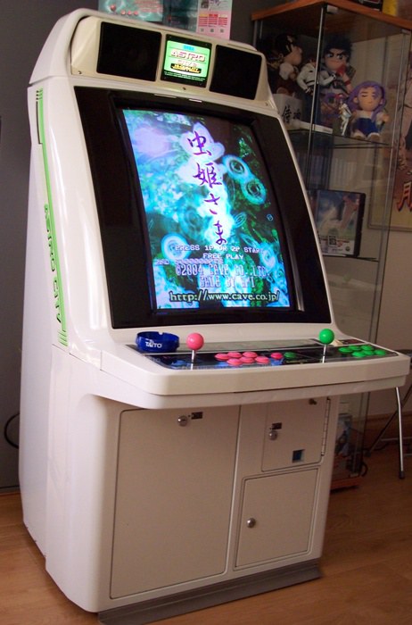
The 1997 revision of the Astro City, often shipped as a dedicated Virtua Fighter cab: game board in a rear compartment, upgraded speakers and PSU, and a revised control panel (button 3 moved below button 1, better for VF). 29″ screen, JAMMA — repair is identical to the Astro City.
Identification¶
| Field | Value |
|---|---|
| Manufacturer | Sega |
| Year | 1997 |
| Type | sit-down candy cab 29″ |
| Base | revision of the Astro City |
| Panel | 2L6B — P/N SAC-2000 (assembly) / SAC-2001 (panel); button 3 below button 1 |
| Note | Virtua Fighter-dedicated version: board in a rear compartment, upgraded speakers/PSU |
Manufacturer figures — export owner's manual¶
The owner's manual archived here is Sega Enterprises' English export edition (USA / Europe / Spain). Its SPECIFICATIONS page gives:
| Item | Value |
|---|---|
| Installation space | 750 (W) × 1,005 mm (D) — 29.5 in. × 39.6 in. |
| Height | 1,445 mm (56.9 in.) |
| Weight | ~125 kg (276 lbs) |
| C.R.T. | 29 INCH COLOR MONITOR |
\"Installation space\" is not the cabinet's footprint
Sega writes Installation space, not dimensions. It is the floor area to allow for — the 所要面積 of its Japanese manuals. Copying "750 × 1,005 × 1,445" as cabinet figures would give a cabinet deeper than it is, service clearance included.
Same convention as on the Super Megalo 2, and the fifth way of stating dimensions met in this wiki.
This cabinet officially exists in 220-240 V
The manual publishes power draw by region, and Europe is in it:
| Supply | Power | Max current |
|---|---|---|
| AC 110 V 50 Hz | 202 W | 2.7 A |
| AC 110 V 60 Hz | 200 W | 2.65 A |
| AC 120 V 60 Hz | 201 W | 2.5 A |
| AC 220 V 50 Hz | 205 W | 1.3 A |
| AC 220 V 60 Hz | 205 W | 1.3 A |
| AC 240 V 50 Hz | 206 W | 1.1 A |
| AC 240 V 60 Hz | 203 W | 1.2 A |
| Taiwan | 203 W max · 160 W min | 2.8 A max · 2.1 A min |
⚠️ This table is what makes the cabinet dual-voltage, and the procedure box below now says so. The Japanese version is 100 V — which is what almost every imported Astro City II is — but Sega did build 220 and 240 V versions. Restated: it holds for a Japanese unit, which is what almost every imported Astro City II is. But Sega did build 220 and 240 V versions, and this manual documents them. Check the cabinet's label before concluding — a step-down transformer on a cabinet already wired for 240 V is as destructive as the reverse.
(Manual's note: "Descriptions in this manual are subject to change without prior notice.")
Differences from the Astro City¶
- Rear compartment for the board (VF) + a beefed-up PSU + improved speakers.
- Button layout: button 3 is moved below button 1 (designed for VF) → SAC-2000/2001 panels differ slightly from the Astro City's CQN-2000.
- Otherwise the same chassis / same repair approach as the Astro City.
⚡ Connectors & power¶
- JAMMA → JAMMA wiring, buttons Control panels.
- 100 V AC candy brick (Japan) → candy PSU + step-down.
Repair¶
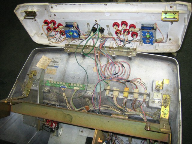
Identical to the Astro City: Nanao MS8/MS9 monitor, recap, harness, candy PSU. See Astro City § Wiring for the detail.
Repair & maintenance
Modernise (video, PSU, JVS, upscaler, PC/FPGA) → Modernising a cabinet. CRT monitor (discharge HV!) → CRT safety + Nanao MS8 / MS9 chassis · candy PSU → PSU repair · recap → Recap.
Procedure — a cabinet that will not start ✅¶
There is a CRT in this cabinet
The tube stays charged with the cabinet unplugged, and the anode cap is the first thing your hand meets behind the monitor. Discharge it, work with one hand, and never alone if you can help it. → CRT safety
This cabinet exists in both low and high voltage
This page documents both a low-voltage version (Japanese or North American market) and a 220-240 V one. Nothing here tells you which one you have.
Read the machine's label before plugging anything in. A step-down transformer on a cabinet already wired for 240 V is every bit as destructive as 230 V into a cabinet built for 100 V. → Cabinet power
What this adds
Ordered for a cabinet, not for a board: mains, low-voltage supply, loom, monitor, then the game. The overwhelming majority of "dead cabinets" are dead for a reason that has nothing to do with the PCB — which is why the board comes last here.
1. Mains, and what sits between it and the cabinet. The switch, the fuse or breaker, the isolation transformer if there is one. A cabinet that shows no sign of life at all is almost never electronic.
2. The low-voltage supply — measured under load. Aim for +5 V where power reaches the board — the JAMMA edge, or the JVS power connector, depending on the cabinet — with the game running, not on an idle bench. If the supply has an adjustment (most candy and JVS bricks do; the ATX brick in a PC cabinet does not), do it then and not before: set off-load, it leaves a board that boots and then glitches. With no adjustment the measurement still earns its keep — it tells you whether the supply holds. Check +12 V too, and −5 V if the board uses it: many do not, and an ATX brick does not provide it. → Cabinet power
3. The loom and the connector. Reseat, and check the grounds — a cabinet with a poor ground gives rolling picture, phantom inputs and noise, all at once, and none of it looks like a wiring fault. → Wiring
4. The monitor. This page does not give a single monitor spec — it covers several cabinets. Check which one you have before concluding anything. CRT: no picture but the tube is warm and there is EHT — that is sync or video, not the tube. No EHT at all — chassis. A picture that shrinks, wanders or shifts colour is a chassis recap, and on these monitors that is a scheduled job, not a repair.
5. Scan rate — the mismatch that breaks nothing. If the board's rate is not one the monitor accepts, you get no picture and nothing is faulty. Check what this cabinet takes against what the board puts out before opening anything. → Modernising a cabinet
6. The control panel. Microswitches and the loom, in that order. A single dead direction is a switch; a whole player dead is the loom or its ground. → Control panels
7. Coin mech and sound. Last, because they hide nothing: a mech that no longer registers is usually dirty or misadjusted, and silence with a good picture points at the amplifier and its supply rails.
See also¶
- Astro City · New Astro City · Aero Table · Sega Model 2 PCB (Virtua Fighter).
Sources & attribution¶
- Sega Enterprises — ASTRO CITY-2 Owner's Manual (English export edition), 60 pp., archived here — SPECIFICATIONS page: Installation space 750 (W) × 1,005 mm (D) ⚠️ installation space, not cabinet figures, Height 1,445 mm, Weight ~125 kg, C.R.T. 29″, and power by region (110/120/220/240 V, plus Taiwan) — it is that table which establishes the official existence of 220-240 V versions. ⚠️ This PDF has no text layer: everything quoted from it was read off the rendered pages. Via Hard*Candy
- Wikipedia — List of Japanese arcade cabinets (Sega Astro City II, 1997, 29″) — https://en.wikipedia.org/wiki/List_of_Japanese_arcade_cabinets
- Arcade Otaku Wiki — Sega Astro City 2 (VF-dedicated version, rear board, upgraded speakers/PSU) — https://wiki.arcadeotaku.com/w/Sega_Astro_City_2
- SOLID-orange — Known official Sega Panels (SAC-2000/2001, button 3 moved) — http://solid-orange.com/1805/
Image:
-
astro-city-2-panneau.jpg— source Hard*Candy (⚠️ no licence statement anywhere on the site) — https://www.hard--candy.com/wiki/candy/Astro_City_2 -
astro-city-2-borne.jpg— source Hard*Candy (⚠️ no licence statement anywhere on the site) — https://www.hard--candy.com/wiki/candy/Astro_City_2
Review & corrections
How this space is used
Spotted a wrong value, an outdated procedure, a chip reference that does not match your board? Say so here, with what you observed (model, board revision, serial number, measurement). Every report is cross-checked against a source before anything changes — an unverifiable correction is published as “reported by …, not cross-checked” rather than silently applied.
Reading is open to everyone; posting requires signing in with Discord. Reports from the wiki's declared reviewers are handled first; anyone else's are read too, but go through a human before anything is changed.