Sega Model 1¶
Sega's first major 3D platform (1992): real-time polygons that launched Virtua Racing then Virtua Fighter. Built on a 3D DSP (TGP) and a 68000. Rare and iconic.
Identification¶
| Field | Value |
|---|---|
| Manufacturer | Sega |
| Year | 1992 |
| Type | Arcade 3D platform (flat/shaded polygons) |
| I/O | JAMMA / dedicated harness |
Architecture¶
| Block | Chip | Clock | Role |
|---|---|---|---|
| CPU | Motorola 68000 | ~10 MHz | game logic |
| 3D geometry | Fujitsu TGP (MB86233, DSP) | polygon transforms/projection | |
| Graphics | real-time polygon engine | flat/Gouraud shading, no texture-mapping (solid colours) | |
| Sound | dedicated Motorola 68000 + Yamaha YM3438 + MultiPCM (315-5560) | FM music + PCM samples |
Sega's first "mainstream" 3D hardware (1992), by the AM2 team (Yu Suzuki). The TGP (Fujitsu MB86233) does all the geometry (transforming and projecting polygons), offloading the 68000.
The 'bare polygon' look (no texture)
The Model 1 does flat / Gouraud shading but no texture-mapping: faces are in solid colours. That's the visual signature of Virtua Fighter / Virtua Racing ("faceted" characters). The Model 2 (1993) precisely adds filtered textures — the next big leap.
Notable games¶
Virtua Racing (1992), Virtua Fighter (1993), Wing War, Star Wars Arcade (1993). A very small catalogue (a handful of titles) — the platform was quickly replaced by the Model 2.
- Multi-cabinet: Virtua Racing could link up to 8 cabinets for multiplayer racing, a feat in 1992.
- Home port: Virtua Racing was ported to the Mega Drive thanks to the SVP chip in the cartridge (see Mega Drive § Hardware quirks).
Preservation & emulation¶
- Emulation: the Model 1 is emulated by MAME (reverse-engineered customs and TGP) — the preservation route, given the rarity of the hardware. No FPGA/MiSTer core (TGP + polygon engine too complex).
- Rare boards: Fujitsu (TGP) customs and video ASIC hard to source → great care when repairing, mind the contacts and the power.
- Targeted recap if image/sound degraded; dedicated monitor (see CRT repair).
Common faults¶
| Symptom | Likely cause | Lead |
|---|---|---|
| No image / no 3D | TGP (MB86233) or video ASIC, power | Diagnosis; Fujitsu customs are irreplaceable → extreme care, mind the contacts |
| No / partial sound | sound 68000 / MultiPCM (315-5560) / YM3438 | Sound-stage diagnosis |
| Crash / unstable image | RAM, interconnects, weak power | Reseat, RAM test, targeted recap |
| Dead controls | harness / dedicated I/O | Check the wiring |
A dedicated monitor (see CRT repair). The real risk is the rarity of the customs: favour software preservation (MAME) over risky teardown.
EPROM repair¶
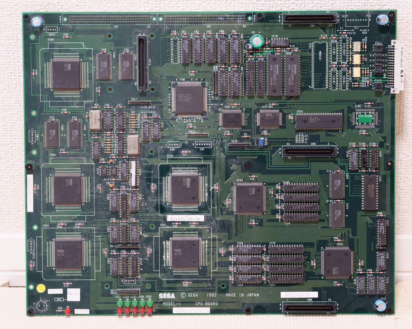
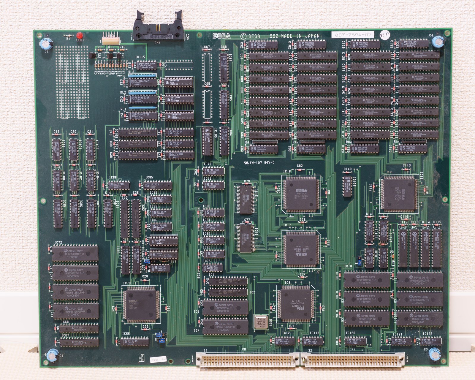
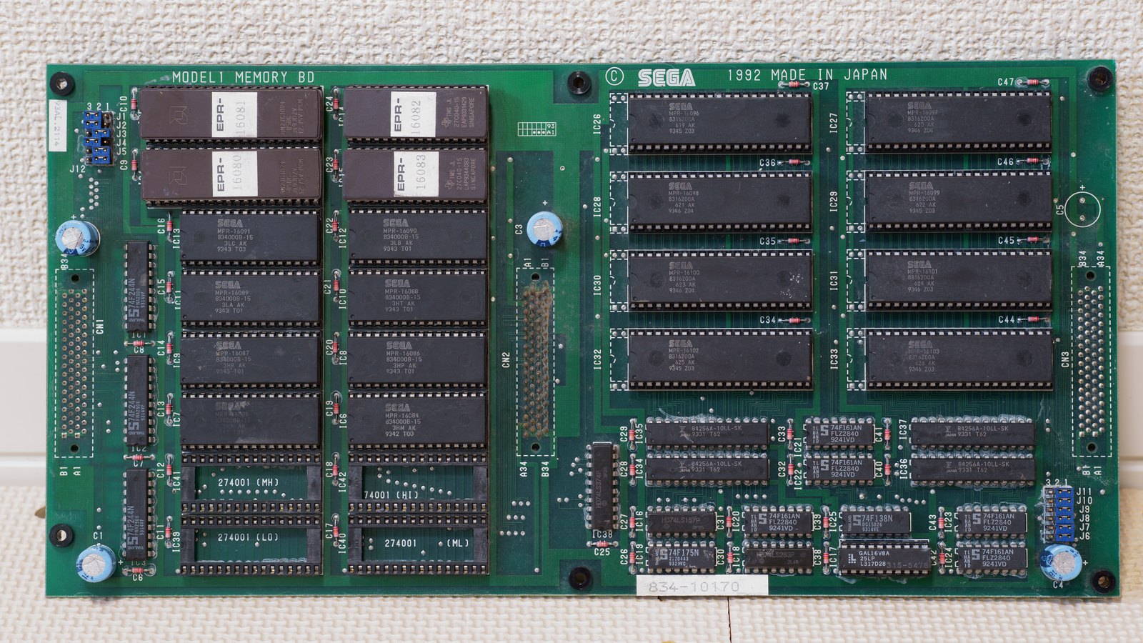
68000 program (+ TGP). Ex. (MAME sega/model1.cpp): Virtua Fighter / Virtua Racing = 10× 27C040 + 2× 27C010 · Star Wars Arcade = 3× 27C040 · Wing War = 8× 27C040. Separate CPU / Memory / Raster boards; 3D data in mask ROM.
Modernisation & mods¶
The common ground for every JAMMA board
Video, power, control panel and upscalers depend on the cabinet rather than the board: everything is centralised in Modernising a cabinet. To run the board outside a cabinet (at home, on a display): supergun.
- Storage 🟡: the game lives in EPROM/mask ROM on the board. Changing or restoring a game means reprogramming the EPROMs (and, for a mask ROM, using a pinout adapter) → EPROM method.
- Media preservation: replacing the original storage, multicarts, ODEs and modern options by family → PCB preservation hub.
- Scan rate 📺: ~24.39 kHz / 57.5 Hz — medium resolution, ⚠️ a 15 kHz-only chassis will not do: you need a medium-res monitor or a tri-sync → tri-sync and upscalers.
(Computed from the MAME sources —
sega/model1.cpp— pixel clock ÷ htotal.) - FPGA / emulation: see the Emulation & FPGA section below.
Repair (technician)¶
- SVP cartridge (Virtua Racing): the geometry DSP is inside the cartridge — dead 3D = SVP/cartridge, not the CPU board.
- Sega customs (video, MultiPCM 315-5560): rare → test RAM + buffers first, the custom last (donor).
- Sound: dedicated 68000 + YM3438 + MultiPCM — silent samples = MultiPCM / sound ROM.
- Capacitors: recap PSU + audio (a costly multi-PCB board → care, inter-board connectors).
→ Methods: PCB fault-finding · Recap · EPROM · Traces & vias
Expected clocks — measurement table ✅¶
Values extracted from the MAME sources for this platform. On a scope or frequency counter, a clock that is missing or off-value points straight at the crystal, the divider or the chip at fault — the fastest starting point on a dead board.
| Component | Expected clock | Role |
|---|---|---|
| V60 | 16 MHz | main CPU |
How to read this table
Several values for one component = several board variants in this family (or several instances of the chip clocked differently). These frequencies are those of the clock signal at the component's input, not of its original crystal — on many boards the clock is divided down from a single master crystal.
Procedure — a dead board, step by step ✅¶
What this adds
The general method lives in PCB diagnosis. This is its application to this platform: the same order, but with the values actually expected here, so you do not have to go back and forth.
Tools: multimeter, oscilloscope (or frequency counter), current-limited bench supply, desoldering braid. → Tooling
If the board is still in a cabinet
A CRT holds its charge with the machine unplugged. → CRT safety
1. Inspection, power off. Corrosion, cut tracks, oxidised EPROM legs, leaking SMD capacitors, dubious earlier repairs.
2. The connector, before anything else. A large share of "dead boards" are a contact problem, not a fault. Clean the contacts with isopropyl alcohol and reseat — not with an abrasive eraser on a gold edge, which takes the plating off and brings the problem back worse. It costs two minutes and settles the question.
3. Power, measured on the board. Aim for +5.0 V measured as close as possible to where power reaches the board — not at the PSU output: the drop is in the loom, and that is exactly what makes a board boot on the bench and not in the cabinet. Where you probe depends on this board's connector — JAMMA edge, JVS loom or a proprietary harness — plenty of makers kept one long after JAMMA arrived — see Identification above. → Wiring Check −5 V and +12 V too if the sound stage uses them. Suspected short: bring it up current-limited and find the hot spot.
4. /RESET. It must release after power-up. Held low = the CPU never starts. A 1–2 Hz loop is not the reset circuit, it is the watchdog: the CPU is crashing at boot, so look at the bus, not at the reset.
5. Clocks — the values expected on this platform.
- V60 → 16 MHz (Main CPU)
No clock on the V60 (16 MHz) and there is no point measuring anything else: the fault is the crystal, the divider, or the chip itself. That single measurement splits a dead board in two.
6. Bus. Activity on the main CPU's address lines tells you whether it is running or frozen. Frozen with good clocks and good reset → work RAM, bus buffers, ROMs.
7. It boots but the picture or the sound is wrong — that is another job: see Common faults on this page, then signal tracing.
Photos / assets¶
(To add: Model 1 board, TGP DSP.)
Sources & attribution¶
- Wikipedia — Sega Model 1 (TGP MB86233, untextured, AM2, games) — CC-BY-SA — https://en.wikipedia.org/wiki/Sega_Model_1
- System16 — Sega Model 1 Hardware — to reference — https://www.system16.com/hardware.php?id=690
- Internal page: Sega Model 2 (next, textured generation)
Image:
-
model1.jpg(CPU board) — htomari, public domain — https://commons.wikimedia.org/wiki/File:SEGA_Model-1_CPU_Board_(50696088478).jpg -
model1-raster-board.jpg— htomari, public domain — https://commons.wikimedia.org/wiki/File:SEGA_Model-1_Raster_Board_(50696922727).jpg -
model1-memory-board.jpg— htomari, public domain — https://commons.wikimedia.org/wiki/File:SEGA_Model-1_Memory_Board_(50696092473).jpg
.jpg)
.jpg)
.jpg)
(The three originals run 5000 × 4000 to 6000 × 3375 at ~22 MB each; they are reduced to 1600 px wide here. Follow the links for full resolution.)
Review & corrections
How this space is used
Spotted a wrong value, an outdated procedure, a chip reference that does not match your board? Say so here, with what you observed (model, board revision, serial number, measurement). Every report is cross-checked against a source before anything changes — an unverifiable correction is published as “reported by …, not cross-checked” rather than silently applied.
Reading is open to everyone; posting requires signing in with Discord. Reports from the wiki's declared reviewers are handled first; anyone else's are read too, but go through a human before anything is changed.