Sega Game Gear
Sega's handheld (1990): basically a pocket Master System in backlit colour. A capital preservation point: its capacitors all die → recap almost mandatory. And a star mod, the McWill screen.
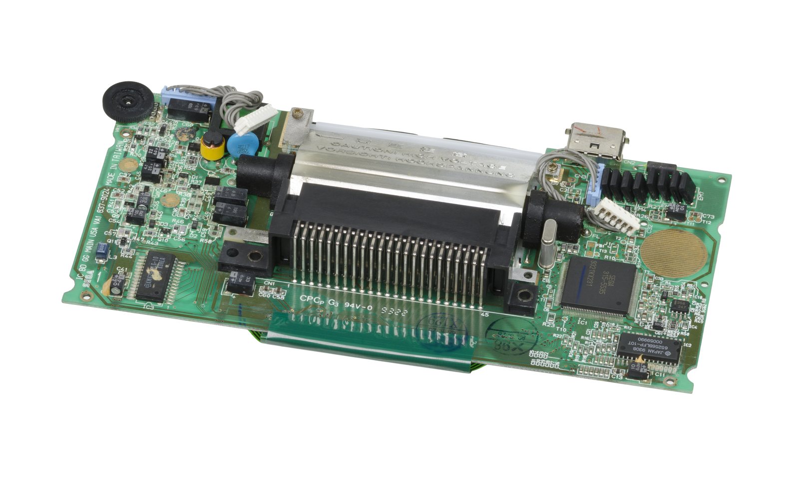
Identification
| Field | Value |
|---|---|
| Manufacturer | Sega |
| Release | 1990 (JP), 1991 (export) |
| Type | 8-bit handheld (Master System architecture) |
| Screen | backlit colour LCD, 160×144 |
| Colours | 4096 palette, 32 on screen |
| Media | Cartridge (+ Master System via Master Gear Converter) |
Architecture
| Block | Component |
|---|---|
| CPU | Zilog Z80 @ 3.58 MHz |
| Video (VDP) | Sega 315-5378 (Master System derivative) |
| Sound | SN76489 (PSG), stereo via headphones |
In practice a portable Master System (same Z80/VDP): the screen shows a 160×144 window of the SMS image, in colour (4096 palette, 32 on screen). No region lock as such (with one exception), but the console's region changes the language of some games and even unlocks extra content in others → see Region. Hence, also, the easy porting of the SMS library.
Peripherals
- Master Gear Converter ("Gear-to-Go"): an adapter to play Master System cartridges on the Game Gear.
- TV Tuner: an analog TV tuner cartridge (watch TV on the screen).
- Gear-to-Gear cable: a 2-player link cable.
- Super Wide Gear: a clip-on magnifier lens; car and external-battery power (battery life on 6 AA being poor).
Preservation
- Flashcart: Game Gear EverDrive (Krikzz).
- Screen: IPS / McWill mods (after recap) for a sharp, bright display. → McWill LCD page
- Emulation: very mature (Genesis Plus GX, MAME).
⚠️ Recap — almost mandatory
The Game Gear's capacitors all die
This is the Game Gear repair: the SMD capacitors (sound and power boards) leak and dry out → no sound, dark/absent image, a console that won't power on. A non-recapped Game Gear almost always needs a recap. Clean the electrolyte, replace with quality SMDs.
Capacitor list ✅
Source: Console5 TechWiki. The Game Gear has 3 boards (main/ASIC, audio, power) and several revisions — identify yours (silkscreened reference), then follow the matching list.
Audio board (all revisions) — 5 caps:
| Ref | µF | V |
|---|---|---|
| C1, C2, C3 | 100 | 6.3 |
| C5, C7 | 47 | 4 |
Power board — 3 caps (VA4: +C9 10 µF/16 V):
| Ref | µF | V |
|---|---|---|
| C5 | 22 | 35 |
| C11 | 100 | 25 |
| C13 | 820 | 6.3 |
Main board (ASIC) — depending on revision:
VA1 single-ASIC (837-8560 / 837-9024) — 12 caps
| Ref | µF | V |
|---|---|---|
| C1 | 33 | 6.3 |
| C4, C11, C14, C42 | 10 | 16 |
| C43 | 22 | 6.3 |
| C45 | 4.7 | 35 |
| C47 | 68 | 6.3 |
| C49 | 100 | 4 |
| C54, C55 | 0.47 | 50 |
| C68 | 100 | 6.3 |
VA0 twin-ASIC (837-7398/7719/7996) — 11 caps
| Ref | µF | V |
|---|---|---|
| C1 | 33 | 6.3 |
| C3, C6, C48 | 10 | 6.3 |
| C31 | 100 | 6.3 |
| C35 | 4.7 | 35 |
| C37 | 68 | 6.3 |
| C39 | 100 | 4 |
| C44, C45 | 0.47 | 50 |
| C49 | 22 | 6.3 |
VA4 (837-9537) — 15 caps
| Ref | µF | V |
|---|---|---|
| C1 | 33 | 6.3 |
| C31, C33 | 10 | 6.3 |
| C36, C44 | 22 | 6.3 |
| C37 | 10 | 16 |
| C38 | 22 | 35 |
| C46 | 22 | 50 |
| C39, C42, C47 | 10 | 50 |
| C40, C41 | 47 | 6.3 |
| C43 | 1 | 50 |
| C55 | 100 | 6.3 |
Board revisions — ⚠️ this decides your screen kit ✅
The Game Gear's basic design changed little, but a number of revisions exist, ranging from simple cosmetic differences to redesigned internals. All games and almost all accessories are compatible across all revisions — that is not the issue.
THE thing to check before ordering a screen kit
Screen replacements intended for the VA0 and VA1 are NOT compatible with the VA4 or the VA5. Each family has a completely different panel and connection scheme. Buying without identifying your board = an unusable kit.
| Revision | Years / regions | What you need to know |
|---|---|---|
| VA0 | 1990-1993, all regions | The "twin ASIC" version: the only revision with a separate VDP and SCA (two SMD chips near the speaker) and the only one with a discrete Z80. Known issue: when playing Master System games (through an adapter, or for the handful of GG games that are actually SMS ROMs in a GG cart), certain coloured blocks appear in odd locations on screen — hard to see on the original screen. Phantasy Star is the notable example. |
| VA1 | 1992-1996, all regions | The "single ASIC" board: Z80, VDP and SCA combined into the 315-5535 ASIC. Fixes the Master System graphical glitch. The final revision for Europe and Japan, and the last to use the Citizen UC-320 LCD. |
| VA4 | 1993-1996, North America only | A different ASIC: 315-5682. Audio preamp and video RAM relocated to the front of the board; backlight components (including the 34 V transformer) moved to the other side. Three different types of electrolytic capacitors, including one through-hole — the only revision with through-hole caps outside the power board. |
| VA5 / 171-7923A | 1994-1996 and 2001, North America | Audio preamp and video RAM back at the rear, backlight on the same side as VA0/VA1. Uses the VA4's 315-5682 ASIC. The 171-7923A variant = Majesco units. |
Board part numbers
| Revision | Part numbers |
|---|---|
| VA0 | 837-7398-0x (Japan) · 837-7719-0x (US) · 837-7996 (Europe) |
| VA1 | 837-8560 (Japan) · 837-9024 (North America) · 837-9130 (Europe) |
| VA4 | 837-9537 · 837-9537-01 (nearly identical, with an extra 100 µF / 6.3 V capacitor in the backlight circuit) |
| VA5 | 837-10766 (Sega) · 171-7923A (Majesco) |
Connectors: VA4 and VA5 break interchangeability
Sega changed the connectors for the power and sound PCBs — AMP CT on VA0/VA1, the far more common JST PH on VA4 and VA5. Direct consequence: power and sound boards from a VA0 or VA1 cannot be used on a VA4 or VA5 without modification. Some VA4s also have a unique power board incorporating a 10 µF SMD electrolytic in addition to the three through-hole capacitors.
The VA4 panel: the wires that break
The VA4's LCD is completely different: three separate cables at the bottom (one per driver IC) and two smaller ribbon cables from the right-hand side of the screen. Above all, it has very thin and fragile wires connecting the ribbon cables to the motherboard: if care is not taken during repairs or modifications, these wires break and create missing lines in the display.
The VA5 returns to a single large ribbon like VA0/VA1 — but its panel is still completely different and still incompatible with VA0/VA1 screen mods.
Identifying your revision without opening up
| Clue | What it tells you |
|---|---|
| Flat lens (and original) | Always a VA0. Flat lenses were fitted to early Game Gears in all regions; the curved "bubble" lens was phased in during 1991-1992. ⚠️ The reverse is not true: some older units with a bubble lens are still VA0. |
| Model number 2110K | Always a VA4. Units manufactured in 1993-1994 additionally have a "3" as the third digit of the serial number. |
| Model number 2110G | Always a VA5 (Majesco included). Original Sega VA5s have a "4" as the third digit of the serial number. |
| Model MK-2110-50 (instead of 2110-50) | A European Game Gear with TMSS. |
AC adapter: the polarity changes by region ⚠️
- Europe and Japan: tip negative adapter, the same as the Master System and the Model 1 Mega Drive.
- United States: tip POSITIVE adapter, EIAJ-03 type, the same as the Model 2 Mega Drive.
Never assume: the wrong polarity is the surest way to kill the power board.
Conductive paint inside the shell (NA and Europe)
On North American and European systems, the inside of the shell is coated with conductive paint to reduce EMI: an aluminized coating on earlier units, a brown or dark grey paint on later ones. Japanese systems have bare plastic with no conductive paint. Worth remembering when modding: it is a conductive surface against which a bare wire or an added board can create a short.
TMSS (the licence screen at boot)
During the VA1's production run, Sega began implementing the TradeMark Security System, presumably to deter unlicensed games as it had on the Mega Drive. The TMSS ROM was always part of the VA1's ASIC, but Sega did not start implementing it until 1993. TMSS is also present on the VA4 and VA5 boards.
- Good news: on the Game Gear, and unlike the Mega Drive, the presence of TMSS causes no game compatibility issues with officially licensed cartridges.
- Disabling it: on all applicable revisions, the TMSS screen can be disabled by shorting "J1" on the motherboard — Sega itself installed a 0 ohm jumper at that location on VA1 units that did not have TMSS.
- US spotting tip: US Game Gears with TMSS have a small silver section on the rear label listing patent numbers; those without TMSS do not.
Region — export ↔ Japan ✅
What it actually changes
Game Gear systems fall into two regions: Japanese and export. With one exception, Game Gear games are not region locked — but a number of them change language according to the console's region, and some even have extra content when played on a Japanese system. That is the whole point of the mod.
The principle: region is controlled by a single pin, usually labelled "JAP" in service manuals. It works exactly like the region selection pin on the Mega Drive — held high (5 V) = export/English, held low (GND) = Japanese. So you simply isolate the pin and wire it to 5 V or GND, or to an SPDT switch for convenient switching.
| Revision | Region pin |
|---|---|
| VA0 | pin 24 of the 315-5378 SCA |
| VA1 / VA4 | pin 142 of the main ASIC (IC1) |
| VA5 / 171-7923A | pin 142 — but already provided with two sets of jumpers (see below), making the mod much easier |
Absolute prerequisite
Make sure your Game Gear is fully working and recapped before attempting this. There is no point chasing a region issue on a machine whose capacitors are dead.
Materials: leaded solder, flux (highly recommended), hookup wire, an SPDT switch, a cordless drill with a step bit (the last four optional depending on the variant chosen). Tools: 4.5 mm gamebit screwdriver, small JIS screwdriver, soldering iron, razor blade.
Disassembly (identical for all regions and revisions)
- Flip the Game Gear face down on a soft surface to avoid scratching the lens. Use the 4.5 mm gamebit for the security screw in the cartridge slot, and the small JIS for the six remaining screws — ⚠️ one screw is hidden inside each battery compartment.
- Carefully pull the back half off and tilt it away, then disconnect the power, audio and speaker connectors to fully separate the two halves.
- (Recommended) Remove the motherboard from the front shell: undo the small JIS screws along the perimeter — ⚠️ but NOT the four screws around the centre near the screen, which secure the entire screen assembly to the motherboard and are not attached to the shell. Undo the two large JIS screws on each side of the cartridge port to release it.
- ⚠️ With the motherboard removed, the bare LCD is exposed: set it on a soft, lint-free surface to avoid scratches and dust.
- Locate the SCA, labelled 315-5378 — the ASIC closest to the cartridge port.
- With the bottom of the board facing you, count the pins on the left side of the SCA from the bottom up: the 7th pin from the bottom is pin 24, the region pin.
- Using a razor blade, very carefully cut the trace going to pin 24. Alternatively you can lift pin 24, but this requires finesse — the pin is delicate and you risk bending adjacent pins.
Permanent region change:
- Japanese → export: wire pin 24 to any 5 V source. Convenient points: pin 35 of the cartridge port or pin 2 of the SCA.
- American/European → Japanese: wire pin 24 to any ground source. Convenient points: pin 19 of the SCA or pin 41 of the cartridge port.
Switchable version: wire the centre tap of an SPDT switch to pin 24, one side tap to 5 V and the other to GND.
- Locate pin 142 of IC1. With the bottom of the board facing you, count the pins on the top of the ASIC from left to right: the 3rd pin from the left is pin 142.
- Using a razor blade, cut the trace going to pin 142 (or lift the pin, with the same caution as above).
Permanent region change:
- Japanese → export: wire pin 142 to 5 V. Convenient points: pin 35 of the cartridge port or pin 28 of IC2 (IC3 on VA4).
- American/European → Japanese: wire to ground. Convenient points: pin 14 of IC2 (IC3 on VA4) or pin 41 of the cartridge port.
Typo in the source
At this last step, the ConsoleMods page writes "pin 24" although the entire VA1/VA4 procedure concerns pin 142 (pin 24 is the VA0's). We flag it without silently correcting it: it is indeed pin 142 that is isolated in the preceding steps.
Switchable version: centre tap of the SPDT to pin 142, side taps to 5 V and GND.
Sega provided jumpers: no trace to cut at the ASIC with a razor blade.
- Locate J2 and J3, to the right of the backlight and above IC1. The lower pads of both jumpers are connected to pin 142 of IC1; the upper pad of J2 goes to 5 V, that of J3 to GND.
- Cut the trace connecting the upper and lower pads of J2 — this isolates pin 142. ⚠️ Do not cut the horizontal trace connecting the two lower pads.
- Permanent conversion to a Japanese system: bridge J3 with a blob of solder or a short wire. Reversible: remove J3 and short J2 again.
Switchable version: centre tap of the SPDT to one of the lower pads of J2 or J3; the upper pads of J2 and J3 go to each side tap of the switch.
Mounting the switch (all revisions): find a clear area where the switch will be largely out of the way when holding the system, drill an appropriately sized hole with a step bit, mount the switch and route the wires clear of the screw bosses and other parts of the shell.
Popular mods — what to buy, where, how
The recap is NOT optional
The Game Gear's SMD capacitors leak and fail systematically → no sound, dim/no screen. Recap first (CXX list below, Console5 source) — everything else depends on it. Tooling: tri-wing (Y) + Phillips, fine iron. Soldering: 🟢 · 🟡 · 🟠 · 🔴.
Screen — replace the (blurry/dim) stock panel
- McWill LCD: a kit that replaces the screen with a sharp, bright LCD, with adjustments and often an added VGA/AV output (great for an external display). Install 🟠 (remove the screen, flex, settings).
- ⚠️ BEFORE BUYING: identify your board revision. A kit made for VA0/VA1 will not fit a VA4 or VA5 → Board revisions.
Why the McWill genuinely makes the difference
There were two original panels, one of them Majesco, which didn't offer much improvement. Swapping the backlight for a newer one saves battery life but doesn't improve the picture enough. And fitting some generic modern LCD forced you to play in half-screen or stretched. McWill's kit is the first to truly fix it: it captures the pixels digitally into RAM instead of doing an analogue conversion — hence scaling effects and scanlines without any lag, with the pixels staying in their right positions.
⚠️ Honest nuance: people often claim the Majesco panels are slightly better, but the condition of the console (capacitors!) makes a far bigger difference than the panel revision.
The McWill's 7 display modes (hold Buttons 1 + 2 + Start)
The internal panel is 320×240, the Game Gear 160×144.
| Mode | Rendering |
|---|---|
| 1 | Scaled resolution: the 160×144 stretched to the panel's 320×240 |
| 2 | Same + vertical scanlines, emulating the look of the original screen — very hard to capture in pictures, but noticeable in person |
| 3 | Doubled horizontal, scaled vertical: the 160 horizontal pixels are doubled to 320 (so perfect horizontal scaling), the vertical remaining stretched |
| 4 | Same + scanlines |
| 5 | Doubled GG resolution (320×288) but only 240 of the 288 vertical pixels displayed: no stretching at all, at the cost of the top and bottom being cut off. In some games this makes no real difference |
| 6 | Same + scanlines |
| 7 | Native resolution: the 160×144 centred within the 320×240 |
In practice: mode 2 (scaled + scanlines) suits most games. A few titles such as Phantasy Star show odd vertical effects in that mode — switch to a doubled mode, where it looks fine.
Bonus: Master System games finally become readable
Unlike on the original screen, Master System games on a Game Gear with a replacement screen look great. McWill added the same scaling options for them: either their original 256×192 resolution (preserving the aspect ratio), or stretched to 320×192 to fill the screen horizontally — both also offering vertical scanlines.
- Other panels now available (postdating the original article): RetroKai's Magic Screen, BennVenn's IPS Screen, RetroSix's Clean Screen, plus various budget screens on online marketplaces.
- IPS (FunnyPlaying): a newer "drop-in" IPS alternative. → McWill LCD page.
- The old backlight / brighter mod is superseded by screen replacement.
- External output (VGA/AV): provided by the McWill VGA or the GGTV (Tim Worthington) board. ⚠️ These are boards that connect to the flex/board: the connection points come with the kit — there's no open chip pinout to transcribe here (unlike home consoles), and we don't invent a point. Follow the kit's docs.
Power / library / misc
- Rechargeable battery / USB-C: the original devours 6 AA cells → an internal battery mod is welcome.
- Flashcart: a compatible Master EverDrive (GG is close to SMS) — games on SD.
- Replacement glass lens (the original scratches).
Common faults
| Symptom | Likely cause | Lead |
|---|---|---|
| No sound | Capacitors (sound board) | Recap |
| Dark / absent image / lines | Capacitors / screen / joints | Recap; else a McWill screen |
| Won't power on | Power caps / fuse / battery contacts | Power recap, check contacts |
| Cartridge not read | Connector oxidation | Cleaning |
| Odd coloured blocks in Master System games | Known VA0 board fault (twin ASIC) — fixed from the VA1 | No hardware fix: it is the revision. → Revisions |
| Missing lines on the display (VA4) | Very thin wires between ribbons and motherboard broken | Extremely careful handling; see the VA4 panel box |
| Screen kit bought turns out incompatible | VA0/VA1 kit fitted to a VA4/VA5 (or vice versa) | Identify the revision before buying → Revisions |
| Power board fried after plugging in the mains adapter | Reversed polarity: US = tip positive, EU/JP = tip negative | Check the adapter — see the polarity box |
Original service manual ✅
Manufacturer manual archived locally. It typically carries the schematics, the block diagram, the expected voltages and waveforms, the parts list and the disassembly procedures — the reference when a symptom matches no known fault.
- *TV Tuner Pack — Sega service manual (the tuner accessory, not the console)* — PDF
- Game Gear — PDF
- Game Gear (JP) — PDF
Status
A manufacturer document with no explicit licence, kept for preservation (machine long out of production). Source: Internet Archive.
Step-by-step disassembly procedures ✅
6 procedures transcribed from the iFixit guides, with difficulty and estimated time.
| Procedure | Difficulty | Time |
|---|---|---|
| Repairing Sega Game Gear Battery | Easy | 5 Minutes |
| Repairing Sega Game Gear Case | Moderate | 20 to 25 minutes |
| Repairing Sega Game Gear Headphone Jack/Volume Wheel | Moderate | — |
| Repairing Sega Game Gear Logic Board | Moderate | — |
| Repairing Sega Game Gear Screen | Moderate | 30 to 45 minutes |
| Repairing Sega Game Gear Speakers | Moderate | — |
Repairing Sega Game Gear Battery
How to replace batteries
- Place your device upside down and locate the two battery compartments.
- Press on the tabs at the bottom of the battery covers then lift up to remove.
Repairing Sega Game Gear Case
How to open the Sega Game Gear case.
- Unscrew all the marked screws with the small Philips head screwdriver.
- The Torx screw requires a bit more turning and patience than the other screws.
- Use tweezers to take all other screws out.
- Use the security screwdriver to get the final screw out.
- Gently open the case by unfolding it over the top of the Sega Game Gear.
- Do not pull the back of the case away, as cables are connected between both sides.
- Gently open the case by unfolding it over the top of the Sega Game Gear.
- Do not pull the back of the case away, as cables are connected between both sides.
Repairing Sega Game Gear Headphone Jack/Volume Wheel
Guide to replace the small logic board that contains the 3.5mm headphone jack as well as the volume wheel.
- Unscrew the screws to remove the metal covering.
Repairing Sega Game Gear Logic Board
A complete guide to replacing the logic board.
- Unscrew all the marked screws.
- Slide the logic board out from under the circular black fastener at the top-left corner of the case.
Repairing Sega Game Gear Screen
A guide to repairing the screen of a Sega Game Gear
- Unscrew all the marked screws.
- Slide the logic board out from under the circular black fastener at the top-left corner of the case.
- Place the board onto a flat surface.
- Small plastic buttons may fall off during this process, save them in a container or a place where they could be found later on.
- Unscrew the marked screws.
- Flip the board, having its back facing up.
- Hold onto the screen in the back, as it will flip open if not held onto.
- Make sure the screen is towards the bottom, as indicated in the second picture.
Repairing Sega Game Gear Speakers
How to repair the speakers of a Sega Game Gear.
- Unscrew the 6 Phillips screws from the logic board.
- Slide the logic board out from under the circular black fastener at the top-left corner of the case.
Source, licence and scope
iFixit guides, under Creative Commons BY-NC-SA — attribution, non-commercial, share-alike. Only the text is reproduced; the step photos stay on iFixit. ⚠️ These guides target the model named in the title: on another revision, the screws and the order of removal may differ.
Procedure — a dead console, step by step ✅
Backlight and battery
The backlight inverter carries a high voltage, live, on a board you are holding. And a swollen lithium cell is not to be pierced or bent — take it out first and put it somewhere safe.
What this adds
Ordered for a console, not for an arcade board: what kills these is almost never the CPU. It is, in real order, the power supply, the capacitors, the drive or the cartridge slot, and only then the logic. → PCB diagnosis
1. The power supply. Two cases, depending on the machine. External brick: ⚠️ read the marking on the machine, next to the socket, and check the adapter against it — voltage and polarity. A centre-negative machine fed centre-positive loses its fuse, sometimes its regulator; do not trust a third-party label or a generic tip. Internal supply (the machine plugs straight into the wall): mains is inside the shell. Unplug, wait, and confirm the large capacitors are discharged before touching the board. Either way, measure under load: a failing supply holds its voltage until it is asked for current.
1b. Battery and its contacts. On this machine, before anything else: corroded battery contacts, or a cell that reads fine off-load and collapses under it, give exactly the symptoms of a dead machine.
2. The fuse. Many of these machines have one right behind the socket — it is the part designed to die. Test it in continuity, out of circuit. A fuse that blows again is a short, not a fuse problem.
3. Capacitors. On most machines of this age this is the default suspect rather than a last resort — leaking SMD electrolytics eat the tracks underneath before they give any other sign. ⚠️ Not all of them are like that: some carry very few and are not recapped on principle. Read what this page says about it before reaching for the iron. → Recap
4. The cartridge connector. Cartridge contacts with isopropyl alcohol, never an abrasive eraser: it takes the gold plating off and the problem comes back worse. On the machine side, inspect the slot pins — splayed, bent or oxidised — and check continuity between slot and board.
5. The screen. Lines, a dead half, a picture that fades: it is almost always the ribbon and its solder joints, not the panel. Reseat before you order anything. If this machine has a TV output — not all of them do — test that too: it tells the screen apart from what feeds it.
6. Still nothing. Now, and only now, the logic: rails on the board, reset, clock, bus. → PCB diagnosis
Photos / assets
(To add: main board + power board, caps area, McWill mod.)
Advanced repair
Full recap all but mandatory (PSU + sound) — see the recap section above — then backlight / screen. Methods: Recap · PCB fault-finding · Traces & vias.
Sources & attribution
- Wikipedia — Game Gear — CC-BY-SA — https://en.wikipedia.org/wiki/Game_Gear
- ConsoleMods Wiki — Game Gear Model Differences — CC-BY-SA — VA0 "twin ASIC" (SMS graphical glitch) / VA1 315-5535 / VA4 and VA5 315-5682, screen kit incompatibility VA0-VA1 vs VA4-VA5, AMP CT → JST PH connectors, board part numbers, no-disassembly tells (flat lens, 2110K, 2110G), adapter polarity, conductive paint, TMSS and the J1 jumper — https://consolemods.org/wiki/Game_Gear:Model_Differences
- ConsoleMods Wiki — Region Switch Mod — CC-BY-SA — the "JAP" pin (pin 24 of the 315-5378 SCA on VA0, pin 142 of IC1 thereafter), J2/J3 jumpers on VA5, full disassembly and per-revision procedures — https://consolemods.org/wiki/Game_Gear:Region_Switch_Mod
- ConsoleMods Wiki — McWill LCD Screen — CC-BY-SA — principle (digital capture into RAM, no lag), 7 display modes, scaling options for Master System games, newer alternatives — https://consolemods.org/wiki/Game_Gear:McWill_LCD_Screen
What we did not transcribe (and why)
The ConsoleMods pages Stereo Audio Mod, RGB out of EXT Port, Game Gear Consolizer, McWill VGA (RGB) Output Mod, Tim Worthington's GGTV, Backlight Replacement and Capacitor Maps are empty to this day (red links). This confirms the position already taken above regarding VGA/AV outputs: no free pinout exists to transcribe, the connection points come with the kit. Nothing has been invented.
- Console5 TechWiki — Game Gear (recap BOM per board/revision) — https://wiki.console5.com/wiki/Game_Gear
Image:
-
game-gear-board.jpg— Evan-Amos, public domain — https://commons.wikimedia.org/wiki/File:Sega-Game-Gear-Motherboard-03.jpg

Review & corrections
How this space is used
Spotted a wrong value, an outdated procedure, a chip reference that does not match your board? Say so here, with what you observed (model, board revision, serial number, measurement). Every report is cross-checked against a source before anything changes — an unverifiable correction is published as “reported by …, not cross-checked” rather than silently applied.
Reading is open to everyone; posting requires signing in with Discord. Reports from the wiki's declared reviewers are handled first; anyone else's are read too, but go through a human before anything is changed.