NEC PC-8001 & PC-6001
NEC's beginnings before the PC-88/98: the PC-8001 (1979), NEC's first successful computer (Z80, a business/hobby reference in Japan), and the PC-6001 (1981, the consumer "papa" — color VDG + PSG sound). Standard JP 8-bit repair: recap, keyboard, PSU.
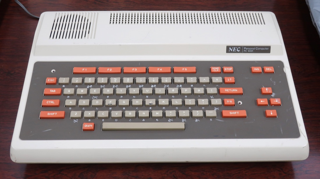
NEC PC-6001 — photo by Darklanlan, CC BY 4.0 (Wikimedia Commons).
Identification
| Model | Year | CPU | Video / Sound | Note |
|---|---|---|---|---|
| PC-8001 | 1979 | µPD780 (Z80) | text/graphics, mono | NEC's first hit; mkII 1983 |
| PC-6001 | 1981 | µPD780 (Z80) | MC6847 (VDG) + PSG AY-3-8910 | consumer, color ("PC-6001 mkII/SR") |
Media: cassette, floppy via external units (PC-8031…), cartridge (PC-6001); RF/composite (PC-6001), RGB/mono per model.
Clocks & frequencies ✅
| Component | Frequency | Role / scope |
|---|---|---|
| NEC μPD780C-1 | 4 MHz | CPU du PC-8001 — compatible Z80 ; 16 Ko de RAM extensible à 32 Ko |
| NEC μPD780C-1 | 3.8 MHz | CPU of the PC-6001 — the same Z80 clone as the PC-8001, clocked lower |
Both machines use the μPD780C-1, NEC's Z80 clone, but not at the same clock: 4 MHz on the PC-8001, 3.8 MHz on the PC-6001. Same part number, two different crystals — check which one you have before calling a clock out of spec.
Why this matters in repair
A clock that is missing or off-value on a frequency counter points straight at the crystal, its divider chain or the component it feeds — the fastest starting point on a machine that will not boot. Source: Wikipedia (CC-BY-SA).
Repair (technician)
- Recap (PSU + board) → Recap.
- Keyboard: contacts / membrane → clean.
- PSU: period regulation → service.
- Cartridge contacts (PC-6001): clean.
- Socketed RAM / ROM: substitution on a dead screen.
Procedure — a dead computer, step by step ✅
What this adds
Ordered for a home computer: what kills these is its power supply, its battery, its capacitors, its socketed RAM and its keyboard — roughly in that order, and well before the CPU. → PCB diagnosis
1. The power supply — measured before it is plugged in. This is the one step not to swap around. On a machine of this age a supply does not simply stop: a 5 V regulator that fails high puts 7, 9, 12 V onto the bus and takes the RAM and the custom chips with it. Measure every rail off the machine, under a dummy load if you can, and only then plug it in.
2. The battery, if it has one. Any RTC or backup cell soldered to a board is a future leak. If yours has one and it has never been changed, take it out before it takes the tracks with it. → Backup batteries
3. Capacitors. Recap is the default on these machines, not a last resort — and on the supply first, since that is what protects everything else. → Recap
4. RAM, on its sockets. These machines were built to be repaired: the RAM, and often the logic, sit in sockets. Reseat everything first — thirty years of oxide is a classic no-boot. Then swap chips: a bad RAM chip usually gives a repeatable pattern of garbage or a screen frozen at a fixed character.
5. The keyboard. A console does not have one; a computer's is a wear part. A membrane keyboard fails as whole dead rows or columns — that is the membrane, not the machine. A mechanical one wants its contacts cleaning, not replacing. Check this page: the failure mode is often documented per model.
6. Storage — tape or disk. Both often come down to the same things: a dirty head, and for tape the azimuth and a belt turned to tar. ⚠️ On the floppy side, check whether the mechanism actually has a belt before looking for one: many do, but some drives are direct drive, and hunting a belt that isn't there means stripping a drive for nothing. A machine that boots but loads nothing is a drive fault, not a logic fault — do not go looking on the board for it.
7. Video output. RF, composite, RGB or a dedicated monitor, depending on the machine (see Identification). Test with something else before you conclude: a period modulator and a modern TV disagree far more often than either is broken.
8. Still nothing. Now the logic: rails on the board, reset, clock, bus. → PCB diagnosis
Modernisation & mods — what to buy, how
- Storage: cassette → audio 🟢 from a PC/phone; community SD solutions on the expansion bus 🟡; floppy → Gotek + FlashFloppy 🟡 on external-FDD configs (PC-8001 mkII + PC-8031).
- Video: RF output (PC-6001) → composite mod 🟡; RGB → OSSC/RGB2HDMI 🟢 for crisp digital.
- Reliability: recap 🟠; check battery/RTC if present; clean contacts.
⚠️ Do not host ROMs/games — method only.
See also
- NEC PC-88 / PC-98 (the lines that followed) · Tandy CoCo (same MC6847 VDG) · Recap.
Sources & attribution
- Photo NEC PC-6001 — Darklanlan, CC BY 4.0, Wikimedia Commons — https://commons.wikimedia.org/wiki/File:NEC_PC-6001.jpg
- Wikipedia — PC-8001 / PC-6001 (Z80, MC6847, AY-3-8910) — CC-BY-SA — https://en.wikipedia.org/wiki/PC-8000_series
-
Established JP retro community knowledge (recap, cassette) — synthesis.
-
Wikipedia — PC-6000 series and the Smithsonian, National Museum of American History (NEC-TREK PC-6001(A) record): the PC-6001's μPD780C-1 runs at 3.8 MHz — two concurring sources — CC BY-SA · https://en.wikipedia.org/wiki/PC-6000_series · https://americanhistory.si.edu/collections/object/nmah_1288701

Review & corrections
How this space is used
Spotted a wrong value, an outdated procedure, a chip reference that does not match your board? Say so here, with what you observed (model, board revision, serial number, measurement). Every report is cross-checked against a source before anything changes — an unverifiable correction is published as “reported by …, not cross-checked” rather than silently applied.
Reading is open to everyone; posting requires signing in with Discord. Reports from the wiki's declared reviewers are handled first; anyone else's are read too, but go through a human before anything is changed.